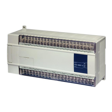
Xinje XP-18 Series User manual

XINJE
XP/XMP-18 series
Integral industrial controller
Operating manual

Xinje
XP/XMP-18
S
eries
Operating manual
V
1.0
Catalog
Preface
Safety Notes
————————————————————
Summarization
————————————————————
Input/output specification and
exterior layout
————————————————————
PLC Function and Application
————————————————————
HMI Function and Application
Extension Ability
1
2
3
4
5

This manual includes some basic precautions which you should follow to keep you safe and protect the
products. These precautions are underlined with warning triangles in the manual. About other manuals that
we do not mention, please follow basic electric operating rules.
Please follow the precautions. If not, it may lead the controlsystem
incorrect or abnormal, even cause fortune lose.
The models could only be used according to the manual, and an only be
used along with the peripheral equipments recognized or recommended
by Xinje Electronic. They could only work normally in the condition of
be transported, kept and installed correctly, also please operate and
maintain them according to the recommendation.
Xinje Electronic Co., Ltd. Copyright reserved
Without exact paper file allowance, copy, translate or using the manual is not allowed. Disobey this,
people should take the responsibility of loss. We reserve all the right of expansions and their design
patent.
Duty Declare
We have checked the manual, its content fits the hardware and software of the products.As mistakes are
unavoidable, we couldn’t promise all correct. However, we would check the data in the manual frequently,
and in the next edition, we will correct the necessary information. Your recommendation would be highly
appreciated
Correct
Application
Precautions

5
SAFETY NOTICE............................................................................................................................8
1. SUMMARIZATION.....................................................................................................................9
1-1. Product summarization......................................................................................................9
1-2. Specs................................................................................................................................11
1-3. Parts explanation..............................................................................................................13
1-4. Outline dimension............................................................................................................15
2. IN-OUT SPECS AND EXTERIOR LAYOUT...........................................................................17
2-1. Input specs.......................................................................................................................17
2-2. Relay output specs and circuit.........................................................................................19
2-3. Transistor output specs and circuit...................................................................................21
3. PLC FUNCTION AND APPLICATION....................................................................................23
3-1. PLC instruction................................................................................................................23
3-2. soft component range.......................................................................................................24
3-3. Set up a project ................................................................................................................28
3-4. communication function..................................................................................................31
4. HMI FUNCTION AND APPLICATION....................................................................................35
4-1. HMI function introduction...............................................................................................35
4-2. Build a project..................................................................................................................36
5. THE EXTENSION ABILITY OF XP/XMP...........................................................................39
5-1. extend BD board..............................................................................................................39
5-2. extend MA model ............................................................................................................42
5-3. Other extension................................................................................................................45
Catalog

7
Thank you for purchasing Xinje XP/XMP series integral industrial controller, please read the
manual before operating.
This manual applies to the XP/XMP series integral industrial controller.
Xinje provides user with press document and tele-document:
nUser CD
Contained software, manual and application examples
nXinje website
Preface
Manual purpose nThis manual provides user with the guide of using and operating our product, it
includes the product characteristics, spec explanation, using method, etc.
nThis manual contains product summarization, exterior layout, PLC program,
and exterior extension.
ØSummarization: introduce the product characteristics, specs, dimension,
installation.
ØExterior layout: introduce the product power spec, in-out layout.
ØPLC program: introduce how to program in PLC.
ØHMI picture: introduce how to edit picture in OP.
ØExterior extension: introduce extension ability of the product.
Suitable people
This manual aims to below users:
nTerminal user
nDebugging person
nTechnology support person
Make sure you have read the safety notice before operating.
Scope
Tele-document

8
Safety notice
Read the manual carefully before operating. Be aware of the safety and correct operation. The
content below is focus on XP/XMP series products only.
Please safekeeping the manual, put in somewhere easy to get and read and give the manual to final
user.
● Do not put the wire close to cable, keep 10cm distance at least.
● Do not change the inside module of product or it may cause fault, error action, loss,
fire.
● When it smelly or noisy, cut the power immediately ( short tweet after power on is
normal ).
● Do not press the screen with pen, screwdriver or other sharp tools, it may cause
screen break or error.
● For installing the product, tighten the screws to avoid loosing.
● Transport, install, store, assemble and maintain the product accurately to avoid
breaking.
● Confirm the power voltage and wire connection before turn on the power in order to
avoid breaking
● Do not touch the connection point to avoid getting an electric shock
● Do not open the back cover board
● Cut all the power before installation and take-down to avoid error and fault
● Please use in the surrounding the manual stated to avoid accident
● Do not use the product under the condition of high frequency radiation, strong
magnetic field to avoid interference
◎Notice items ◎
ATTENTION
DANGEROUSNESS

9
1. Summarization
1-1. Product summarization
XP/XMP-18 series integral industrial controller integrated human machine interface (HMI) and
PLC (XC1, XC2, XC3 series). It can instead of HMI and PLC to fulfill the control function. It can
save space with slim outline and improve the convenience of maintenance.
uIntegrate logical control, analog quantity in-out and HMI into the product
On-off quantity input: 10 points, optical coupling insulation
On-off quantity output: 8 points, relay output/transistor output/R&T mixture output
Analog quantity: XP/XMP can extend BD board to realize analog quantity in-out control
Easy edit of the HMI picture, rich function
uLCD display: 192×64 pixel ( 3.7 inch ), LCD useful life can reach 0.5 million hours
u26 function keys can be redefined by user
uSensitive and accurate key-press
uMultifunctional download port: HMI and PLC use one download cable
uWaterproof level is IP20
uSmall structure, space saving
uSimple and modern outline
XMP series
Relay output
Transistor
output
Relay&Transistor
output
XMP1-
18R
XMP1-18T
XMP1-18RT
XMP2-18R XMP2-18T
XMP2-18RT
XMP3-18R XMP3-18T
XMP3-18RT
XP series
Relay
output
Transistor
output
Relay&Transistor
output
XP1-18R XP1-18T XP1-18RT
XP2-18R XP2-18T XP2-18RT
XP3-18R XP3-18T XP3-18RT
Product characteristics
Type List

10
1 2 3 4
1: Name XP, XMP series
2: PLC Type 1: XC1 series
2: XC2 series
3: XC3 series
3: In-out points 18: Input 10 points, output 8 points
4: Output Type R: Relay output
T: Transistor output
RT: Relay&Transistor output
Notice: XMP series exclude XMP2-32 series products in this manual. About these products,
please refer to Integral Controller Manual XMP2-32.
Type Name

11
1-2. Specs
Item Specs
Power supply
voltage DC12V~DC24V
Power Less than 10W(TYP2.0W)
Power cut
moment permit Less than 20ms
Endurable
voltage
AC1000V/10MA for 1minute ( between signal
and ground )
Electric
Insulated
impedance
About 10MΩ,DC500V ( between signal and
ground )
Operating
temperature 0~50℃
Storage
temperature –10~60℃
Environment
temperature 20~85% ( No dew )
Endurable
quiver 10~25Hz ( X, Y, Z direction for 30 minutes )
Anti-jamming Voltage Noise: 1000Vp-p
Air No causticity gas
Surrounding
Protection According to IP20
Cooling mode Natural wind
Dimension 172.0*121.0*56.5
Configuration
Panel open
aperture
dimension
164.0*113.0
Download port RS-232
Port Com port RS-485
General Specs

12
Specs
Item XP1/XMP1 XP2/XMP2 XP3/XMP3
Program executing format Loop scan format, time scan format
Program format Instruction, C language and ladder chart
Processing speed 0.5us
Power cut retaining Use Flash ROM and Li battery
User program’s capacity 32KB 128KB 128KB
I/O points Input 10 points, output 8 points
Interior coil’s points (M) 448 8768 8768
Points 80 640 640
Timer
(T)Specs
100mS timer:Set time 0.1~3276.7 seconds
10mS timer:Set time 0.01~327.67 seconds
1mS timer:Set time 0.001~32.767 seconds
Points 48 640 640
Counter
(C)Specs 16 bits counter:set value K0~32767
32 bits counter:set value -2147483648~2147483647
Data Register(D)288 words 2612 words 9024 words
SpecsItem
XP series XMP series
Type Kelly/Blue LCD
Screen
dimension 3.7 inch
Useful life Over 20000 hours, 25℃, 24hours operating
Display area 192*64
Contrast Regulation resistance available
Character
setting Chinese, English
Character size Lattice font, vector font
Characteristic
Touch mode Touch unable Matrix or resistance
touch mode
Picture 64KB Flash ROM
Register Data 4KB SRAM
HMI Specs
PLC Specs

13
Flash ROM Register(FD)
510 words 512 words 2048 words
Extension D register (ED) - - 16383
High speed processing
function
- High speed count, pulse output,
external interrupt
Setting of time scan space 0~99mS
Password protection 6 bits ASCII
Self diagnose function Power on self-diagnose, Monitor timer, grammar check
Note: The user program capacity is referred to the capacity under “secret downloading mode”.
1-3. Parts explanation
Configuration
5 6 7 8
4321
01
2 3 4 5
9876 Number
key
Screen area
Function
key

14
24V, 0V: power supply input
A, B: RS-485 com port
COM: common ground
X: Input
Y: Output
Program port is a RS-232 com port which has double functions of downloading PLC program and
HMI pictures. The pins function of the port is as below:
Pin Function
Pin2 RXD
Pin3 TXD
Pin5 GND
Pin7 RTS
Xinje provides special program cable to download the PLC program or HMI program. You also
can make the cable by yourself. Please see the pin connection between PC and the port.
MODE:
XP3-18
R
SN: 20060502118
DATE: 20060510
无锡市信捷科技电子有限公司 Points connect
with BD board
Program
port
Power
supply
RS-485 Com port Output points Input points
In-out points arrangement
Program port

15
DB9 pins DB9 pins
XP/XMP PC
2 RXD 2 RXD
3 TXD 3 TXD
5 GND 5 GND
7 RTS 7 CTS
Communication port ( A and B ) is a RS-485 com port. This port is used to connect other devices.
Please refer to paragraph 3-4 for details.
1-4. Outline dimension
Unit: mm
Communication port
Outline dimension
121
162
111
56.5 172
6 7 8 9
5432
1 0
1 2 3 4
8765

16
Unit: mm
Installation dimension
164
113

17
2. In-out specs and exterior layout
2-1. Input specs
DC power
R3
R4
R2
R1
X*7
X*0
COM
supply
Because there is no 24V power supply inside XP/XMP, it needs an outside supplier to drive the
photo-electricity switch sensor. The supplier should be DC 24V±4V. The output transistor of
sensor should be NPN open collector.
DC power
DC24V
power supply
R3
R4
R2
R1
X*7
X*0
COM
+5V
R5R6
LED
I=7mA
sensor
supply
Input signal’s
voltage
DC24V±10%
Input signal’s
current
7mA/DC24V
Input ON current Above 4.5mA
Input OFF current
Below 1.5mA
Input response time
About 10ms
Input signal’s
format
Contact input or
NPN open collector
transistor
Circuit insulation Photo-electricity
coupling insulation
Input action’s
display
LED light when
input ON
Basic unit
Input connection

18
lInput points
Connect input point and com point with non-voltage point or NPN open collector transistor to
turn on the input.
lInput loop
The first loop and the second loop are insulated by optical coupler, the second loop has C-R
filter which can prevent wrong action caused by industry noise or input points oscillation. As
the result, there will be a response delay for 10ms to the input points. There is digital filter in
the input points.
lInput sensitivity
Input current is DC 24V 7mA. To make the input reliable, the ON current should be above
3.5mA, the OFF current should be below 1.5mA.
Typical connection

19
2-2. Relay output specs and circuit
Type R /RT output T output
Relay output R:Y0~Y7
RT:Y4~Y7
Power supply Below AC250V、DC30V
Circuit insulation Machinery insulation
Action indication Produce close sound
Resistor
load
3A
Inductance
load
80VA
Maximum
load
LED load 100W
Minimum load DC5V 2mA
OFF→ON
10msResponse
time ON→OFF
10ms
NO
lOutput points
Relay output has two common points. Different units can drive the loader of different
power-voltage systems.
lLoop insulation
It is electric insulated between relay output point and outside load circuit.
lAction indication
Relay output coil produces close sound when it is on.
lResponse time
The response time is about 10ms transferring the ON or OFF signal from relay output coil to
the output connection.
lOutput current
Output current is 3A per point to drive resistor load for voltage below AC250V.
Inductor load is below 80VA ( AC100V or AC200V ) and light load is below 100W
( AC100V or AC200V ).
lOpen leakage current
There is no leakage current when output point is OFF, it can drive neon light.
lUse life of relay output point
The standard life of inductor load such as contactor, solenoid valve: according to our
experiment results, 20VA load is about 3 million times, 35VA load is about 1 million times,
80VA load is about 0.2 million times. However, the life will extend if parallel connect surge
Relay output specs
Relay output circuit

20
absorber with the load.
+24V
circuitdrive
relay
Y*3
Y*2
Y*1
Y*0
M
5A~10A
Load
~
AC power
<AC250V
Relay output
To avoid burning PLC basic circuit
set a fuse every 4 points
supply
Note: T type has no relay output, do not connect AC220V, or the product will be broken.
lFor DC inductor load, please parallel connect with commutate diode. If not connect with the
commutate diode, the point’s life will be decreased greatly. Please choose the commutate
diode which allow inverse voltage endurance up to 5~10 times of the load’s voltage, ordinal
current exceeds load current.
lParallel connect AC inductor load with surge absorber can reduce noise and extend useful life
of the points.
Output connection example
Constitution of output circuit
DC load
AC load

21
2-3. Transistor output specs and circuit
Transistor output can divide into two types: high speed pulse output and normal transistor output.
Type RT output T output
High speed pulse
output point
Y0~Y1 Y0~Y1
Power supply Below DC5~30V
Maximum current 50mA
Maximum pulse
frequency
200KHZ
Type RT output T output
Transistor output point Y2~Y3 Y2~Y7
Power supply Below DC5~30V
Circuit insulation Optical coupling insulation
Resistor
load
0.4A
Inductor
load
12W/DC24V
Maximum
load
Light load 1.5W/DC24V
Minimum load DC5V 2mA
OFF→ON Below 0.2msRepose
time ON→OFF Below 0.2ms
lOutput point
Highspeed pulse output
Normal transistor output
Normal transistor output circuit

22
There is one common point for basic unit transistor output
lPower supply
The load circuit power supply should be steady voltage of DC5~30V.
lCircuit insulation
The inside circuit of XP/XMP is insulated with output transistor by optical coupler.
lAction indication
When driving optical coupling,LED lights,output transistor is ON.
lResponse time
From optical coupler driving (or cut) to transistor ON (or OFF), the time is below 0.2ms.
lOutput current
The current is 0.4A per point. But due to restriction of temperature going up, the total current
is 0.8Aevery four points.
lOpen current
Less than 0.1mA.
use suitable fuse for the load
To avoid burning PLC basic circuit
DC power
DC5~30V
Load
Load
Load
Load
1A
circuitdrive
photo-electricity
Y*4
Y*5
Y*6
Y*7
supply
This manual suits for next models
19
Table of contents
Other Xinje Controllers manuals