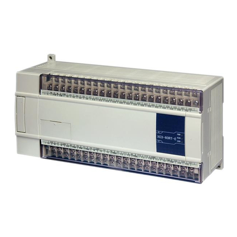
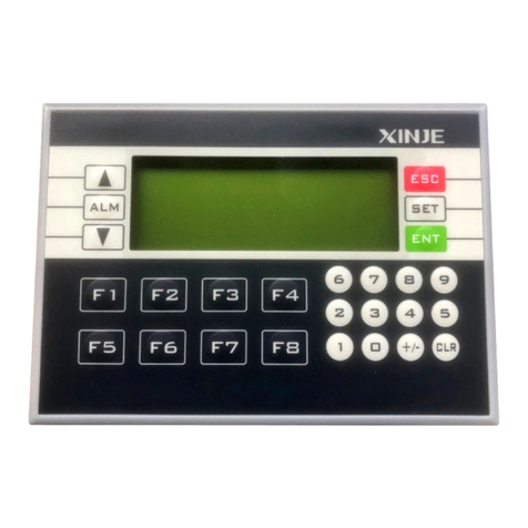
Xinje XD Series User manual

XD/XL series PLC
User manual [Instruction]
WUXI XINJE ELECTRIC CO., LTD.
Data No. PD05 20201022 3.5

1
XD/XL series PLC
User manual[Instruction]
1 Preface
—————————————————
2 Programming summary
—————————————————
3 Soft component functions
—————————————————
4 Basic program instructions
—————————————————
5 Applied instructions
—————————————————
6 High speed counter
—————————————————
7 Pulse output
—————————————————
8 Communication functions
—————————————————
9 PID functions
—————————————————
10 C function block
—————————————————
11 Sequences BLOCK
—————————————————
12 Special function instructions
—————————————————
13 Applications
—————————————————
14 Q&A
—————————————————
15 Appendixes
—————————————————

2
Basic explanation
Thank you for purchasing Xinje XD/XL series PLC.
This manual mainly introduces XD/XL series PLC instructions.
Please read this manual carefully before using and wire after understanding the content.
About software and programming instructions, please refer to related manuals.
Please hand this manual over to operation users.
Notices for users
Only experienced operator can wire the plc. If any problem, please contact our technical
department.
The listed examples are used to help users to understand, so it may not act.
Please conform that PLC specifications and principles are suitable when connect PLC to
other products. Please conform safety of PLC and machines by yourself when use the PLC.
Machines may be damaged by PLC errors.
Responsibility declaration
The manual content has been checked carefully, however, mistakes may happen.
We often check the manual and will correct the problems in subsequent version. Welcome to
offer advices to us.
Excuse us that we will not inform you if manual is changed.
Contact information
If you have any problem about products, please contact the agent or Xinje company.
Tel: 0086 510-85134136 85123803
Fax: 0086 510-85111290
Address: Building 7 fourth floor, No.100, Dicui Rd, Wuxi, China.
Code : 214072
WUXI XINJE ELECTRIC CO., LTD. copyrights
Do not copy or use manual without written permission. Offenders should be
responsible for losses. Please keep all copyrights of our company including practical
modules, designed patents and copyrights mentioned in register.
2015, 5, 12

3
Catalog
1 PROGRAMMING SUMMARY.................................................................................................9
1-1.PLC FEATURES ............................................................................................................................9
1-2.PROGRAMMING LANGUAGE.......................................................................................................10
1-2-1
.
Type ...................................................................................................................................10
1-2-2
.
Alternation.........................................................................................................................10
1-3
.
Programming mode............................................................................................................... 11
2 SOFT COMPONENT FUNCTION..........................................................................................12
2-1.SUMMARY OF THE SOFT COMPONENTS ......................................................................................12
2-2.STRUCTURE OF SOFT COMPONENTS...........................................................................................15
2-2-1
.
Structure of Memory ..........................................................................................................15
2-2-2
.
Structure of Bit Soft Components.......................................................................................17
2-3.SOFT COMPONENTS LIST ...........................................................................................................18
2-3-1
.
Soft Components List .........................................................................................................18
2-4.INPUT/OUTPUT RELAYS (X, Y) ...................................................................................................35
2-5.AUXILIARY RELAY (M, HM, SM) ..............................................................................................37
2-6.STATUS RELAY (S, HS)...............................................................................................................38
2-7.TIMER (T, HT) ...........................................................................................................................39
2-8.COUNTER ( C, HC )....................................................................................................................43
2-9.DATA REGISTER (D, HD)............................................................................................................48
2-9-1
.
Word consist of bits............................................................................................................51
2-9-2
.
Offset application ..............................................................................................................52
2-10.FLASH REGISTER (FD, SFD, FS) ..............................................................................................53
2-11.CONSTANT ...............................................................................................................................54
2-12.PROGRAMMING PRINCIPLE.......................................................................................................55
3 BASIC PROGRAM INSTRUCTIONS....................................................................................59
3-1.BASIC INSTRUCTIONS LIST.........................................................................................................59
3-2. [LD] , [LDI] , [OUT] ...................................................................................................................61
3-3. [AND] , [ANI].............................................................................................................................62
3-4. [OR] , [ORI] ................................................................................................................................63
3-5. [LDP] , [LDF] , [ANDP] , [ANDF] , [ORP] , [ORF]....................................................................64
3-6. [LDD] , [LDDI] , [ANDD] , [ANDDI] , [ORD] , [ORDI],[OUTD] ..........................................65
3-7. [ORB]..........................................................................................................................................66
3-8. [ANB]..........................................................................................................................................67
3-9. [MCS] , [MCR] ...........................................................................................................................68
3-10. [ALT].........................................................................................................................................69
3-11. [PLS] , [PLF] .............................................................................................................................70
3-12. [SET], [RST] .............................................................................................................................71
3-13.【 CNT】【 CNT_D】【 DCNT】【 DCNT_D】【 RST】FOR THE COUNTERS..............................72
3-14. [TMR], [TMR-A] FOR TIMERS...................................................................................................74
3-15. [END]........................................................................................................................................74

4
3-16. [GROUP] , [GROUPE] .............................................................................................................75
3-17. PROGRAMMING NOTES ...............................................................................................................76
4 APPLIED INSTRUCTIONS.....................................................................................................78
4-1.APPLIED INSTRUCTIONS LIST.....................................................................................................78
4-2.READING METHOD OF APPLIED INSTRUCTIONS .........................................................................82
4-3.PROGRAM FLOW INSTRUCTIONS ................................................................................................84
4-3-1
.
Condition Jump [CJ] .........................................................................................................84
4-3-2
.
Call subroutine [CALL] and Subroutine return [SRET]....................................................85
4-3-3. Flow [SET], [ST], [STL], [STLE] .......................................................................................87
4-3-4
.
[FOR] and [NEXT] ..........................................................................................................92
4-3-5
.
[FEND] and [END]..........................................................................................................94
4-4. DATA COMPARE FUNCTION ........................................................................................................95
4-4-1
.
LD Compare [LD] .............................................................................................................96
4-4-2
.
Serial Compare [AND]......................................................................................................97
4-4-3
.
Parallel Compare [OR].....................................................................................................98
4-5.DATA MOVE INSTRUCTIONS.....................................................................................................101
4-5-1
.
Data Compare [CMP].....................................................................................................101
4-5-2
.
Data zone compare [ZCP]...............................................................................................102
4-5-3. MOV [MOV]......................................................................................................................103
4-5-4. Data block Move [BMOV] ................................................................................................105
4-5-5
.
Data block Move [PMOV] ..............................................................................................106
4-5-6
.
Fill Move [FMOV] ..........................................................................................................107
4-5-7
.
Floating move [EMOV]...................................................................................................109
4-5-8
.
FlashROM Write [FWRT] ...............................................................................................110
4-5-9
.
Zone set [MSET].............................................................................................................. 111
4-5-10
.
Zone reset [ZRST]..........................................................................................................112
4-5-11
.
Swap the high and low byte [SWAP].............................................................................. 113
4-5-12
.
Exchange [XCH] ...........................................................................................................114
4-6.DATA OPERATION INSTRUCTIONS.............................................................................................116
4-6-1 Addition [ADD] .................................................................................................................116
4-6-2
.
Subtraction [SUB] ........................................................................................................... 118
4-6-3
.
Multiplication [MUL]......................................................................................................120
4-6-4
.
Division [DIV].................................................................................................................121
4-6-5
.
Increment [INC] & Decrement [DEC]............................................................................123
4-6-6
.
Mean [MEAN] .................................................................................................................124
4-6-7
.
Logic AND [WAND], Logic OR[WOR], Logic Exclusive OR [WXOR] ..........................125
4-6-8
.
Logic converse [CML].....................................................................................................127
4-6-9
.
Negative [NEG]...............................................................................................................128
4-7.SHIFT INSTRUCTIONS ...............................................................................................................129
4-7-1
.
Arithmetic shift left [SHL], Arithmetic shift right [SHR].................................................129
4-7-2
.
Logic shift left [LSL], Logic shift right [LSR] .................................................................131
4-7-3
.
Rotation shift left [ROL], Rotation shift right [ROR]......................................................132
4-7-4
.
Bit shift left [SFTL] .........................................................................................................134
4-7-5
.
Bit shift right [SFTR].......................................................................................................135

5
4-7-6
.
Word shift left [WSFL].....................................................................................................136
4-7-7
.
Word shift right [WSFR]..................................................................................................137
4-8.DATA CONVERT........................................................................................................................138
4-8-1
.
Single word integer converts to double word integer [WTD]..........................................139
4-8-2
.
16 bits integer converts to float point [FLT] ...................................................................140
4-8-3
.
Float point converts to integer [INT] ..............................................................................141
4-8-4
.
BCD convert to binary [BIN] ..........................................................................................142
4-8-5
.
Binary convert to BCD [BCD] ........................................................................................144
4-8-6. Hex converts to ASCII [ASCI] ...........................................................................................145
4-8-7
.
ASCII convert to Hex.[HEX] ...........................................................................................146
4-8-8
.
Coding [DECO] ..............................................................................................................147
4-8-9
.
High bit coding [ENCO] .................................................................................................150
4-8-10
.
Low bit coding [ENCOL] ..............................................................................................152
4-8-11
.
Binary to Gray code [GRY] ...........................................................................................154
4-8-12
.
Gray code to binary [GBIN].........................................................................................155
4-9.FLOATING NUMBER OPERATION ...............................................................................................156
4-9-1
.
Floating Compare [ECMP].............................................................................................157
4-9-2
.
Floating Zone Compare [EZCP].....................................................................................158
4-9-3
.
Floating Addition [EADD] ..............................................................................................160
4-9-4
.
Floating Subtraction [ESUB] ..........................................................................................161
4-9-5
.
Floating Multiplication [EMUL].....................................................................................162
4-9-6
.
Floating Division [EDIV]................................................................................................164
4-9-7
.
Float Square Root [ESQR] ..............................................................................................165
4-9-8
.
Sine [SIN] ........................................................................................................................166
4-9-9
.
Cosine [COS] ..................................................................................................................167
4-9-10
.
TAN [TAN].....................................................................................................................168
4-9-11
.
ASIN [ASIN] ..................................................................................................................169
4-9-12
.
ACOS [ACOS] ...............................................................................................................170
4-9-13
.
ATAN [ATAN] ................................................................................................................171
4-10.RTC INSTRUCTIONS...............................................................................................................172
4-10-1
.
Read the clock data [TRD]............................................................................................172
4-10-2
.
Write Clock Data [TWR] ...............................................................................................173
4-10-3
.
Clock compare [TCMP] ................................................................................................174
5 HIGH SPEED COUNTER (HSC)..........................................................................................177
5-1.FUNCTIONS SUMMARY.............................................................................................................177
5-2.HSC MODE..............................................................................................................................178
5-3.HSC RANGE ............................................................................................................................179
5-4.HSC INPUT WIRING.................................................................................................................180
5-5.HSC PORTS ASSIGNMENT .........................................................................................................180
5-6.AB PHASE COUNTING FREQUENCY DOUBLING SETTING............................................................186
5-7.HSC INSTRUCTION...................................................................................................................187
5-7-1
.
Single phase HSC [CNT].................................................................................................187
5-7-2
.
AB phase HSC [CNT_AB]...............................................................................................188
5-7-3. HSC reset [RST] ................................................................................................................189

6
5-7-4
.
Read HSC value [DMOV] ...............................................................................................189
5-7-5
.
Write HSC value [DMOV]...............................................................................................190
5-7-6
.
The difference between HSC and normal counter ...........................................................191
5-8.HSC EXAMPLE ........................................................................................................................192
5-7.HSC INTERRUPTION.................................................................................................................194
5-7-1
.
Function overview and panel configuration ....................................................................194
5-9-2
.
Single phase 100-segment HSC [CNT] ...........................................................................196
5-9-3
.
AB phase 100-segment HSC [CNT_AB]..........................................................................197
5-9-4
.
Interruption flag of HSC..................................................................................................198
5-9-5
.
Setting value meaning in absolute or relative mode ........................................................198
5-9-6. HSC interruption cycle mode ............................................................................................201
5-9-7. CAM function of high speed counter interruption .............................................................203
5-9-8. Interruption using notes and parameter address...............................................................204
5-9-9. Application of HSC interruption........................................................................................205
6 COMMUNICATION FUNCTION.........................................................................................212
6-1.SUMMARY................................................................................................................................212
6-1-1
.
COM port ........................................................................................................................212
6-1-2
.
Communication parameters ............................................................................................220
6-2.MODBUS COMMUNICATION ...................................................................................................220
6-2-1
.
Function overview ...........................................................................................................220
6-2-2
.
Changing of Modbus instruction .....................................................................................221
6-2-3
.
Modbus communication address .....................................................................................222
6-2-4 Modbus data format .........................................................................................................232
6-2-5
.
Communication Instructions............................................................................................238
6-2-6
.
Modbus serial port configuration....................................................................................248
6-2-7
.
Modbus Communication application...............................................................................252
6-2-8
.
Application ......................................................................................................................253
6-3. FREE COMMUNICATION ..............................................................................................................256
6-3-1
.
Free communication mode ..............................................................................................256
6-3-2
.
Serial port configuration .................................................................................................257
6-3-3
.
Suitable occasion.............................................................................................................258
6-3-4
.
Free communication instruction ......................................................................................259
6-3-5
.
Free communication example..........................................................................................262
6-4.COMMUNICATION FLAG AND REGISTER ....................................................................................268
6-5.READ WRITE SERIAL PORT PARAMETERS ..................................................................................271
6-5-1
.
Read serial port parameters [CFGCR] ...........................................................................271
6-5-2
.
Write serial port parameters [CFGCW]..........................................................................272
6-5-3
.
Serial port parameter name and setting ..........................................................................273
7 PID CONTROL FUNCTION .................................................................................................275
7-1.PID INTRODUCTION .................................................................................................................275
7-2.INSTRUCTION FORM.................................................................................................................275
7-3.PARAMETERS SETTING.............................................................................................................277
7-3-1
.
Register and their functions.............................................................................................278

7
7-3-2
.
Parameters Description...................................................................................................283
7-4.AUTO TUNE MODE ..................................................................................................................284
7-5.ADVANCED MODE....................................................................................................................287
7-6.APPLICATION OUTLINES ...........................................................................................................288
7-7.APPLICATION ...........................................................................................................................289
8 C LANGUAGE FUNCTION BLOCK...................................................................................294
8-1.SUMMARY................................................................................................................................294
8-2.INSTRUCTION FORMAT.............................................................................................................294
8-3.OPERATION STEPS....................................................................................................................295
8-4.IMPORT AND EXPORT THE FUNCTIONS......................................................................................298
8-5.EDIT THE FUNC BLOCKS ..........................................................................................................299
8-6.PROGRAM EXAMPLE ................................................................................................................301
8-7.APPLICATION NOTES ................................................................................................................303
8-8.FUNCTION TABLE ....................................................................................................................305
9 SEQUENCE BLOCK..............................................................................................................307
9-1.CONCEPT OF THE BLOCK .......................................................................................................307
9-2.CALL THE BLOCK...................................................................................................................308
9-2-1
.
Add the BLOCK...............................................................................................................308
9-2-2
.
Move the BLOCK ............................................................................................................ 311
9-2-3
.
Delete the BLOCK...........................................................................................................312
9-2-4
.
Modify the BLOCK ..........................................................................................................312
9-3.EDIT THE INSTRUCTION OF THE BLOCK..................................................................................314
9-3-1
.
Command item.................................................................................................................314
9-3-2
.
Pulse Item ........................................................................................................................315
9-3-3
.
Wait Item..........................................................................................................................316
9-3-4
.
Module Read and Write
(
FROM/TO
)
instruction........................................................317
9-4.RUNNING FORM OF THE BLOCK .............................................................................................318
9-5.BLOCK INSTRUCTION EDITING RULES ....................................................................................320
9-6.BLOCK RELATED INSTRUCTIONS ............................................................................................322
9-6-1
.
Instruction explanation....................................................................................................322
9-6-2
.
The timing sequence of the instructions...........................................................................324
9-7.BLOCK FLAG BIT AND REGISTER.............................................................................................328
10 SPECIAL FUNCTION INSTRUCTIONS...........................................................................329
10-1. PULSE WIDTH MODULATION [PWM]....................................................................................329
10-2. FREQUENCY MEASUREMENT [FRQM]......................................................................................332
10-3. PRECISE TIMING [STR]............................................................................................................336
10-4. INTERRUPTION [EI], [DI], [IRET] ............................................................................................342
10-4-1
.
External Interruption.....................................................................................................342
10-4-2. TIMING INTERRUPTION .........................................................................................................348
11 COMMON QUESTIONS AND ANSWERS........................................................................350
APPENDIX SPECIAL SOFT COMPONENTS.......................................................................368

8
APPENDIX 1.SPECIAL AUXILIARY RELAY .......................................................................................368
APPENDIX 2.SPECIAL DATA REGISTER ...........................................................................................374
APPENDIX 3. SPECIAL FLASH REGISTER............................................................................................381
APPENDIX 4. PLC RESOURCE CONFLICT TABLE .................................................................................384
APPENDIX 5. PLC FUNCTION CONFIGURATION LIST...........................................................................385

9
1 Programming Summary
XD/XL series PLC accept the signal and execute the program in the controller, to fulfill the
requirements of the users. This chapter introduces the PLC features, two kinds of
programming language and etc.
1-1.PLC Features
XD/XL series PLC support two kinds of program language, instruction and ladder chart, the
two kinds of language can convert to each other.
To avoid the stolen or wrong modifying of user program, we encrypt the program. When
uploading the encrypted program, it will check in the form of password. This can protect the
user copyright; meanwhile, it limits the downloading, to avoid change program by mistake.
XD/XL series added new register FS. (For different XD/XL models, please check the Data
monitor in XDPpro software for FS register range, common range is FS0~FS47). FS value
can be modified but cannot be read through Modbus instruction. FS cannot be compared to
register but only constant in XDPpro software. The value cannot be read. FS is used to protect
the user’s copyright. The register D, HD… can replace by FS.
When the user program is too long, the comments of program and soft components are
necessary in order to change the program easily later.
Add offset appendix (like X3[D100], M10[D100], D0[D100]) after coils, data registers can
make indirect addressing. For example, when D100=9, X3[D100] =X[3+9]=X14;
M10[D100]=M19, D0[D100]=D9
XD/XL series PLC has enough basic instructions including basic sequential control, data
moving and comparing, arithmetic operation, logic control, data loop and shift etc.
XD/XL series PLC also support interruption, high speed pulse, frequency testing, precise
time, PID control and so on.
XD/XL series PLC support C language; users can call the C program in ladder chart. This
function improves the programming efficiency.
Programming Language
Security of the Program
Program comments
Rich Basic Functions
C Language Function Block
Offset Function

10
XD/XL series PLC support “Stop PLC when reboot” function. When there is a serious
problem during PLC running, this method can stop all output immediately. Besides, if the
COM port parameters are changed by mistake, this function can help PLC connect to the PC.
XD/XL series PLC has many communication modes, such as Modbus-RTU, Modbus-ASCII.
When the COM port parameters are changed, the new parameters will be valid immediately
without restarting the PLC.
Wait time can be added before Modbus instructions.
1-2.Programming Language
1-2-1.Type
XD/XL series PLC support two types of programming language:
Make the program with instructions directly, such as “LD”, “AND”, “OUT” etc. This is the
basic input form of the programs, but it’s hard to read and understand;
E.g.: step instruction operand
Make sequential control graph with sequential control signal and soft components. This
method is called “Ladder chart”. This method uses coils and contactors to represent sequential
circuit. The ladder chart is easy to understand and can be used to monitor the PLC status
online.
E.g.:
X0 X2
Y5
Y5
1-2-2.Alternation
The two kinds of programming language can be transformed to each other.
0
LD
X000
1
OR
Y005
2
ANI
X002
3
OUT
Y005
Instruction
Stop PLC when reboot
Communication Function

11
1-3.Programming mode
The two kinds of programming language can be input directly in the editing window. The
ladder chart window has hint function which improves the programming efficiency greatly.
Some instruction is complicated to use, like pulse output, PID etc. XDPPro software has the
configuration window for these special instructions. User just needs to input parameters in the
configuration window without remembering complicated instructions. The following window
is multi section pulse output.
For the details of instruction configuration, please refer to XD/XL series PLC user manual
【software part】.
Instruction
Ladder
Direct Input
Instruction Configuration

12
2 Soft Component Function
In chapter 1, we briefly introduce the programming language. However, the most important
element in a program is the operands. These elements include the relays and registers. In this
chapter, we will describe the functions and using methods of these relays and registers.
2-1.Summary of the Soft Components
There are many relays, timers and counters inside PLC. They all have countless NO
(Normally ON) and NC (Normally Closed) contactors. Connect these contactors with the
coils will make a sequential control circuit. Next we will introduce these soft components.
The functions of input relays
The input relays are used to receive the external ON/OFF signal, the sign is X.
Address Assignment Principle
In each basic unit, X address is in the form of octal, such as X0~X7, X10~X17 …
The extension module address: module 1 starts from X10000, module 2 starts from
X10100… XD1/XD2/XL1 cannot support extension module. Up to 10 extension modules
can be connected to the XD3/XL3 main unit.
XD5/XDM/XDC/XD5E/XDME/XDH/XL5/XL5E/XLME can connect 16 extension
modules.
Extension BD board: BD 1 starts from X20000; The 24-32 points PLC can connect one
extended BD board and the 48-60 points PLC can connect two extended BD boards. (16-
point PLC does not support extended BD board, XL/XDH series does not support extended
BD board.)
The address number of the left extended ED module, starting from X30000 according to
octal system, XD/XL series PLC supports a left extended I/O ED module. (XDH cannot
support ED module)
Using notes
The digital filter is used in the input filter of the input relay. Users can change the filter
parameters by setting the special register SFD0, default value is 10ms, modification range: 0
~ 1000ms.
There are enough input relays in the PLC. The input relay whose address is more than input
points can be seemed to auxiliary relay.
Function of the output relays
Output relays are the interface to drive the external loads, the sign is Y;
Address Assignment Principle
In each basic unit, Y address is in the form of octal, such as Y0~Y7, Y10~Y17 …
The extension module address: module 1 starts from Y10000, module 2 starts from Y10100…
Output Relay (Y)
Input Relay (X)

13
XD1/XD2/XL1 does not support extension modules, XD3/XL3 can accept 10 extension
modules, XD5/XDM/XDC/XD5E/XDME/XDH/XL5/XL5E/XLME can accept 16 extension
modules.
Expanding the address number of BD board, starting from X20000 according to octal system,
24-32 points PLC can extend one BD board, 48-60 points PLC can extend two BD boards.
(16-point PLC does not support extended BD board, XL/XDH series does not support
extended BD board.)
The address number of the left extended ED module, starting from Y30000 according to octal
system, XD/XL series PLC supports a left extended input and output ED module. (XDH
cannot support ED module)
Using notes
There are enough output relays in the PLC. The output relay whose address is more than
output points can be seemed to auxiliary relay.
Function of Auxiliary Relays
Auxiliary relays is internal relays of PLC, the sign is M and HM;
Address assignment principle
In basic units, assign the auxiliary address in decimal form
Using notes
This type of relays are different from the input/output relays, they can’t drive external load
and receive external signal, but only be used in the program;
Retentive relays can keep its ON/OFF status when PLC power OFF;
Function of status relays
Used as relays in Ladder, the sign is S, HS.
Address assignment principle
In basic units, assign the address in decimal form.
Using notes
If it is not used as operation number, they can be used as auxiliary relays, programming as
normal contactors/coils. Besides, they can be used as signal alarms, for external diagnose.
Function of the timers
Timers are used to accumulate the time pulse like 1ms, 10ms, 100ms etc. when reach the set
value, the output contactors acts, represent sign is T and HT.
Address assignment principle
In basic units, assign the timer address in decimal form. Please refer to chapter 2-2 for details.
Time pulse
Auxiliary Relays (M, HM)
Status Relays (S, HS)
Timer (T, HT)

14
There are three timer pulses: 1ms, 10ms, and 100ms. For example, 10ms means accumulate
10ms pulses.
Accumulation/not accumulation
The timer has two modes: accumulation timer means even the timer drive coil is OFF, the
timer will still keep the current value; while the not accumulation timer means when the
accumulation value reaches the set value, the output acts, the accumulation value reset to 0.
According to different application purposes, the counters contain different types:
For internal counting (for general using/power off retentive usage)
16 bits counter: for increment count, the count range is 1~32,767
32 bits counter: for increment count, the count range is 1~2,147,483,647
These counters are for PLC internal signal. The response speed is one scan cycle or longer.
For High Speed Counting (Power-off retentive)
32 bits counter: the count range is -2,147,483,648~ +2,147,483,647
(Single phase increment count, AB phase count). For special input terminals.
The high speed counter will not be affected by PLC scanning period. For increment mode, it
can count max 80KHz pulses; for AB phase mode, it can count max 50KHz pulses.
Address assignment principle
In basic units, assign the timer address in decimal form.
Function of Data Registers
Data Registers are used to store data, the sign is D and HD.
Address assignment principle
The data registers in XD/XL series PLC are 16 bits (the highest bit is sign bit), combine two
data registers together is for 32 bits (the highest bit is sign bit) data processing.
Using notes
Same to other soft components, data registers also have common type and power-off retentive
type.
Function of FlashROM registers
FlashROM registers are used to store data, the sign is FD.
Address assignment principle
In basic units, FlashROM registers address is in form of decimal;
Using notes
Even the battery powered off, this area can remember the data. So this area can store
important parameters. FlashROM can be writen for about 1,000,000 times, and it takes time
when writing. Frequently writing can cause permanent damage for FD.
Counter (C, HC)
Data Register (D, HD)
FlashROM Register (FD)

15
The Function of Secret Register
A part of the FlashROM register is used to store data in soft components, which are
represented by the symbol FS. The values in the FS register can be written but can not be
read, so they can be used to protect the intellectual property rights of users.
Address Allocation Principle
In the basic unit, FS registers are addressed in decimal numbers.
Since the number of FS registers of different types of PLC may be different, please refer to
the "PLC Initial Settings" shown in the online PLC software, generally FS0-FS47.
Attention Points in Use
The storage area can remember data even if the battery is powered down, so it can be used to
store important process parameters. FS can be written about 1,000,000 times, and it takes
more time to write each time. Frequent writing will cause permanent damage to FS, so it is
not recommended that users write frequently. When using MOV instruction to transmit data
to FS, the rising edge is valid.
The value of the soft element can be set arbitrarily in the FS register, but the value of the
register can not be read (always returned to 0); and it can not be compared with the register
in the PLC software, only with the constant, so the actual value of the register can not be
read.
B means Binary, K represents Decimal, H represents Hexadecimal. They are used to set
timers and counters value, or operands of application instructions. For example hex FF will
be HFF.
2-2.Structure of Soft Components
2-2-1.Structure of Memory
In XD/XL series PLC, there are many registers. Besides D, HD, FlashROM registers, we can
also combine bit to register.
For common use, 16 bits
For common use, 32 bits (combine two continuous 16-bits registers)
For power off retentive use, cannot modify the retentive range
For special use, occupied by the system, can’t be used to common instruction parameters
For offset use (indirect assignment)
Constant (B) (K) (H)
Data Register D, HD
Special secret Register (FS)

16
Form: Dn[Dm], HDn[Dm], Xn[Dm] , Yn[Dm] , Mn[Dm] , etc.
MOV D10[D0] D100
SM0
M2
Y0[D0]
MOV K5 D0
SM2
MOV K0 D0
When D0=0, D100=D10, Y0 is ON.
When M2 turns from OFF to ON, D0=5, then D100=D15, Y5 is ON.
Therein, D10[D0]=D[10+D0], Y0[D0]=Y[0+D0].
The word offset combined by bit: DXn[Dm] represents DX[n+Dm].
The soft components with offset, the offset can represent by soft component D, HD.
For common usage, 16 bits, represent the current value of timer/counter;
For common usage, 32 bits, (combine two continuous 16 bits registers)
To represent them, just use the letter+address method, such as T10, C11, HT10, HC11.
E.g.
MOV D0T11
M0
T11 Y1
X0
TMR T11 K99 K100
In the above example, MOV T11 D0, T11 represents word register;
LD T11, T11 represents bit register.
For power off retentive usage, 16 bits
For power off retentive usage, 32 bits, (combine two continuous 16 bits registers)
For special usage, occupied by the system, can’t be used as common instruction parameters
For common usage, 16 bits, (combine 16 bits)
The soft components which can be combined to words are: X, Y, M, S, T, C, HM, HS, HT,
HC.
Format: add “D” in front of soft components, like DM10, represents a 16-bits register from
M10~M25
Get 16 bits beginning from DXn, cannot beyond the soft components range;
The word combined by bits cannot do bit addressing;
E.g.:
Timer T, HT/Counter C, HC
FlashROM Register FD
Register combined by bits

17
MOV K21 DY0
M0
MOV K3 D0
M1
MOV DX2[D0] D10
SM0
When M0 changes from OFF to ON, the value in the word which is combined by Y0~Y17
equals to 21, i.e. Y0, Y2, Y4 become ON.
Before M1 activates, if D0=0, DX2[D0] represents a word combined by X2~X21.
If M1 changes from OFF to ON, D0=3, then DX2[D0] represents a word combined by
X5~X24.
2-2-2.Structure of Bit Soft Components
Bit soft components include X, Y, M, S, T, C, HM, HS, HT, HC. Besides, the bit of the
register also can be used as bit sofst component.
Input Relay X, octal form
Output Relay Y, octal form
Auxiliary Relay M, HM, S, HS; decimal form
Auxiliary Relay T, HT, C, HC, decimal form. The represent method is same to registers, so
we need to judge if it’s word register or bit register according to the instruction.
Composed by bit of register, support register D
Represent method: Dn.m (0≤m≤15): for example D10.2 means the second bit of D10
The represent method of bit with offset: Dn[Dm].x
Bit of register can’t compose to word soft component again;
E.g.:
D0.4 Y0
D5[D1].4Y1
D0.4 means when the fourth bit of D0 is 1, set Y0 ON.
D5[D1].4 means bit addressing with offset, if D1=5, then D5[D1] means the fourth bit of D10
The Bit of register
Relay

18
2-3.Soft Components List
2-3-1.Soft Components List
XD1 series PLC soft components list:
Name
Range
Points
16 I/O
32 I/O
16
32
X
Input points
X0~X7
X0~X17
8
16
Y
Output points
Y0~Y7
Y0~Y17
8
16
X
Input points※3
X10000~X10077(#1 expansion
module)……
X11100~X11177(#10 expansion
module)
640
Y
Output points※3
Y10000~Y10077(#1 expansion
module)……
Y11100~Y11177(#10 expansion
module)
640
X
Input points※4
X20000~X20077(#1 expansion
BD)
X20100~X20177(#2 expansion
BD)
128
Y
Output points※4
Y20000~Y20077(#1 expansion
BD)
Y20100~Y20177(#2 expansion
BD)
128
X
Input points※5
X30000~X30077(#1 expansion ED)
64
Y
Output points※5
Y30000~Y30077(#1 expansion ED)
64
M
Internal relay
M0~M7999
8000
HM
HM0~HM959※1
960
SM
Special purpose SM0~SM2047※2
2048
S
Flow
S0~S1023
1024
HS
HS0~HS127※1
128
T
Timer
T0~T575
576
HT
HT0~HT95※1
96
ET
Precise timer ET0~ET31
32
C
Counter
C0~C575
576
HC
HC0~HC95※1
96
HSC
High speed counter HSC0~HSC31
32
D
Data register
D0~D7999
8000
HD
HD0~HD999※1
1000
SD
Special purpose SD0~SD2047
2048
HSD
Special purpose HSD0~HSD499※2
500
FD
FlashROM
register
FD0~FD5119
5120
SFD
Special purpose SFD0~SFD1999※2
2000

19
FS
Special secret
register
FS0~FS47
48
ID※6
Main body
ID0~ID99
100
Expansion module
ID10000~ID10099(#1 expansion
module)……
ID10900~ID10999(#10 expansion
module)
1000
expansion BD
ID20000~ID20099(#1 expansion
BD)
ID20100~ID20199(#2 expansion
BD)
200
expansion ED
ID30000~ID30099(#1 expansion
ED)
100
QD※
7
Main body
QD0~QD99
100
Expansion module
QD10000~QD10099(#1 expansion
module)……
QD10900~QD10999(#10 expansion
module)
1000
expansion BD
QD20000~QD20099(#1 expansion
BD)
QD20100~QD20199(#2 expansion
BD)
200
expansion ED
QD30000~QD30099(#1 expansion
ED)
100
SEM
Special coil of
Sequence block
instruction WAIT
SEM0~SEM31
32
XD2 series PLC soft components list:
Name
Range
Points
16 I/O
24 I/O
32 I/O
48 I/O
60 I/O
16
24
32
48
60
X
Input points
X0~X7
X0~X15
X0~X21
X0~X33
X0~X43
8
14
18
28
36
Y
Output points
Y0~Y7
Y0~Y11
Y0~Y15
Y0~Y23
Y0~Y27
8
10
14
20
24
X
Input points※3
X10000~X10077(#1 expansion
module)……
X11100~X11177(#10 expansion
module)
640
Y
Output points※3
Y10000~Y10077(#1 expansion
module)……
Y11100~Y11177(#10 expansion
module)
640
X
Input points※4
X20000~X20077(#1 expansion BD)
X20100~X20177(#2 expansion BD)
128
Other manuals for XD Series
4
This manual suits for next models
3
Table of contents
Other Xinje Controllers manuals