XKGlow SAR90 User manual

XK-SAR':'SAR90'/'SAR360'Lighting'System'''''''''''''''
SAR Bar Installation
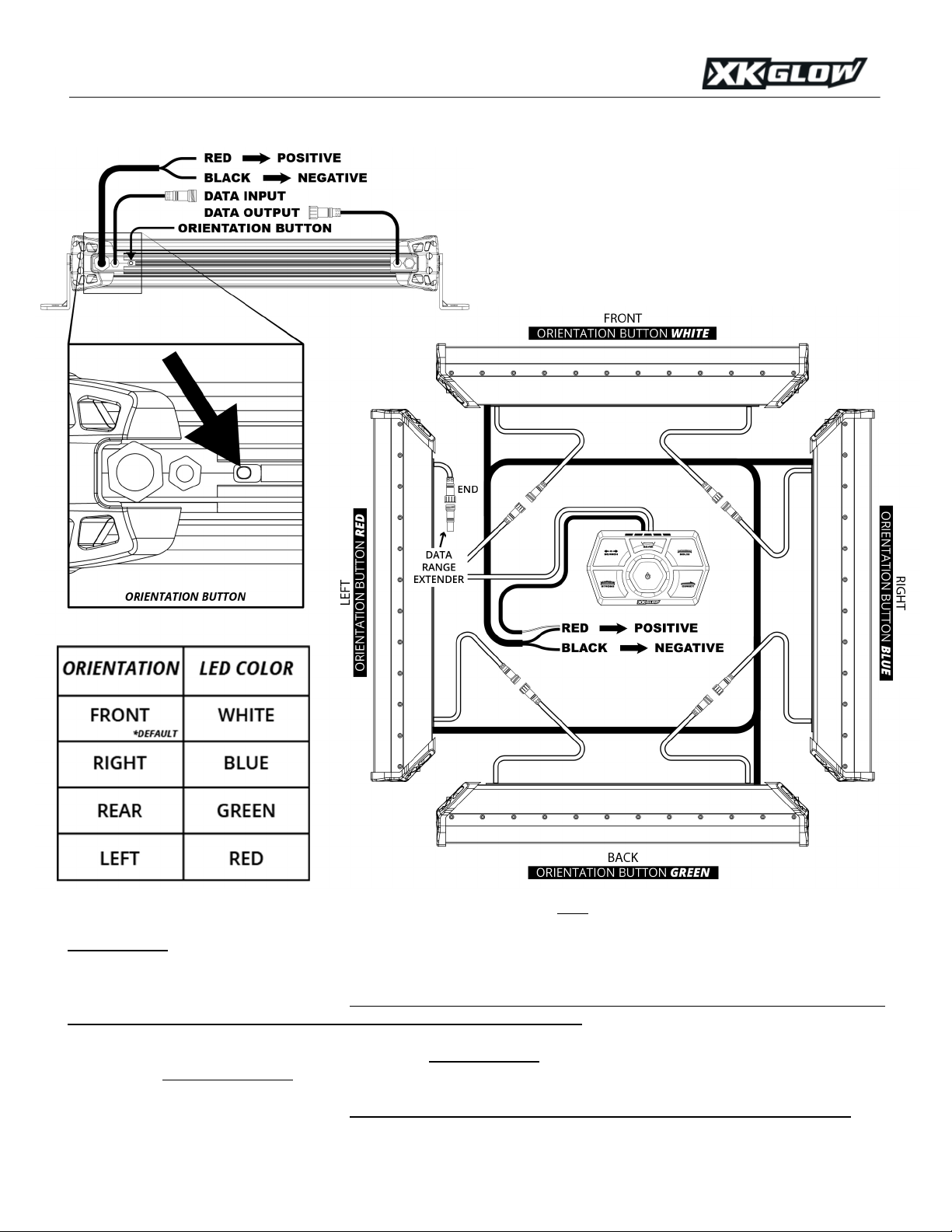
Before installing the components on the vehicle, begin with a quick test off of the vehicle. Follow the wiring information on the next
page by first connecting all of the data input and data output wires between the SAR Controller and the SAR Bars. Then proceed by
connecting all RED power wires to positive voltage and the BLACK power wires to a ground. The vehicle’s battery will be sufficient
for this test. Power on and test functionality of the system. It is not necessary to set orientation at this point as they may be mixed up
when mounted on the vehicle.
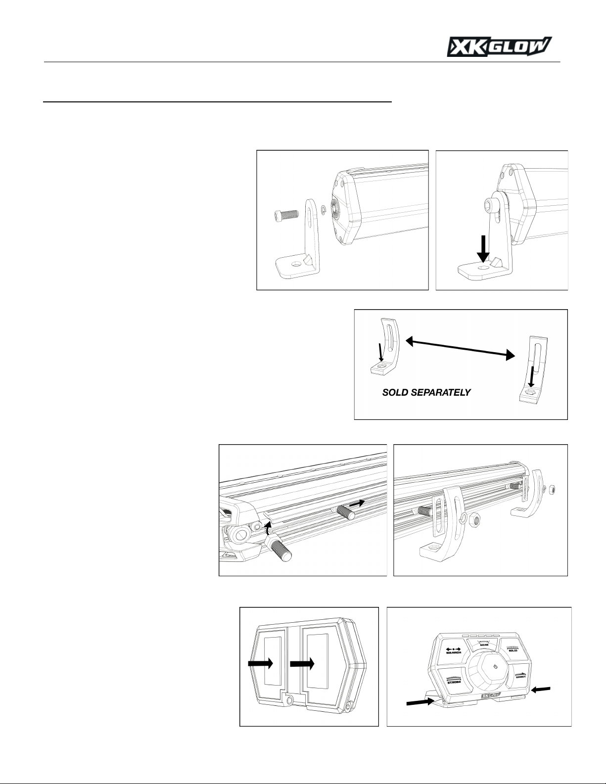
Mounting SAR Bars with L-brackets –
Included with each SAR Bar are two end-mount L-
brackets. Following the diagram to the right, loosely
mount the L-brackets to the ends of the light bar
with the lock washer between the bar and the
bracket. Place the light bar onto the vehicle in the
desired location. Mark the holes indicated by the
arrow and drill out the holes using a 3/8” drill bit.
Secure the brackets with the included hardware. To
finish the install, adjust light bar rotation to desired
position and then tighten the end cap hex cap
screws.
Mounting SAR Bars with Adjustable Rear Brackets
(SOLD SEPARATELY) –
This portion covers installation of the SAR Bars
with the optional Adjustable Rear Brackets. Begin first by mounting the
brackets to the desired location on the vehicle. Please note that the MAX
spacing between these brackets will be 7 inches LESS than the length of
the bar (see arrow between brackets in diagram to the right). Example- on a
20 inch SAR Bar, the maximum distance these brackets can be apart is 13
inches. Measure, mark and drill a 3/8” hole for each bracket (downward
facing arrows to the right). Secure the brackets to the vehicle using the
supplied hardware.
Insert the supplied bolts into the rear of
the SAR Light bar. These will slide in on
the side nearest the orientation button as
shown in the first diagram to the right.
Insert the rubber spacers onto the bolts.
Position the light bar near the brackets,
insert the bolts into the brackets, and
secure with the included nuts and lock
washers. To adjust rotation or to move the
light bar from left to right, simply loosen
these nuts, reposition, and snug back.
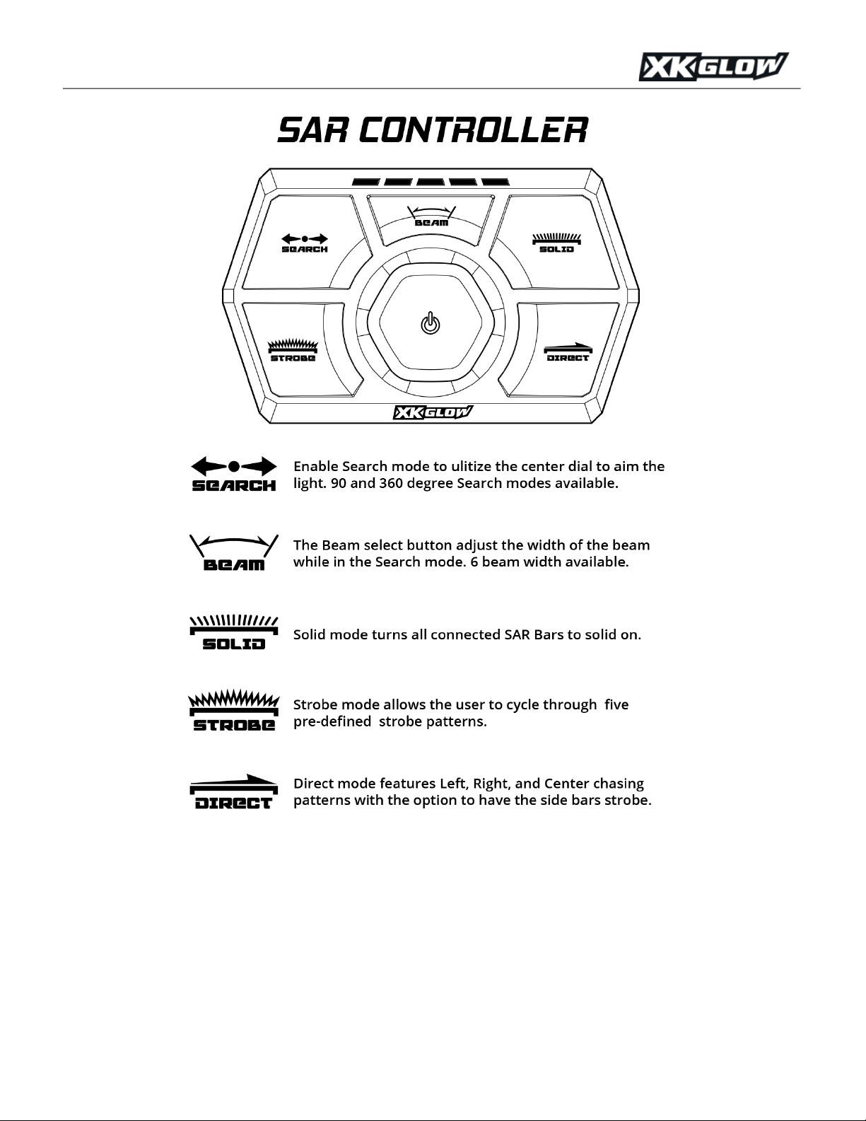
SAR Controller Installation
Find a convenient location to mount the SAR
Controller. Using the provided 3M tape, firmly
press the controller into the location. Use the
center channel to feed the wiring through to the
rear if necessary.
Once mounted, use the two screws pointed out
in the second diagram to the right to adjust the
angle of the SAR Controller. When in place,
tighten the screws to lock the angle in place.

XK-SAR':'SAR90'/'SAR360'Lighting'System'''''''''''''''
Wiring Information
Using the above wiring diagram, wire up each component of the SAR System. Each SAR Light Bar and the SAR Controller must be
connected to constant power and ground. 12-gauge wiring or lower is required. Plug the SAR Controller into the first SAR Light Bar
(data input wire) in the series. Using the data output wire from that bar, connect the next light bar in series. Repeat until all SAR Light
Bars on the vehicle are connected. Please note – the order in which the bars are connected is not important. The orientation is set
using the orientation button on the back of the light bar. Once the light bars are connected to power, use the chart above and set the
orientation button to the corresponding color. If the total data wire length exceeds 24ft, please connect the data range extender plug
(included in SAR 360 4-light bar system) to the output data wire of the last light bar.
Each SAR Light Bar must be connected to constant power with an inline fuse (included), however these can be connected to different
power sources with common ground. Running multiple SAR Light Bars off of shared power and ground wires is fine, however, we do
recommend staying below 40 amps per wire set. If your system exceeds 40 amps, simply run another power and ground wire to the
SAR Light Bars with an additional inline fuse. The controller red wire must be connected to the same power as the 1st SAR bar.
There are 3 wires coming out of the back of each SAR Light Bar.
Looking at the rear of the light bar as shown to the left; starting
from the left side is the power wire to go to power and ground.
Data input wire will either plug directly into the SAR Controller
or into another SAR Light Bar on the vehicle. Next to the data
input wire is the orientation button. This is to set the light bar
to forward, left, right, or rear facing. On the right side of the bar
is the data output wire which goes to the next SAR Light Bar.
'

XK-SAR':'SAR90'/'SAR360'Lighting'System'''''''''''''''
The SAR Controller is the command center of the SAR System. The single controller is capable of controlling every
SAR Light Bar equipped to a vehicle.
To t ur n t he l i g ht s ON/OFF, click the center dial. The green indicator LEDs at the top of the SAR Controller will illuminate.
These indicator LEDs will respond to different modes when activated for visual confirmation.

XK-SAR':'SAR90'/'SAR360'Lighting'System'''''''''''''''
Search Mode allows the user to direct the light where necessary. To activate Search, simply click the Search button. The
forward-facing light bars will illuminate and can be controlled via the center turn dial. Turn the dial clockwise to direct
right, and counterclockwise to direct left.
90 Degree Search
vs
360 Degree Search
–
•Use the 90-degree setting when only forward-facing light bars are used. The 90-degree mode will lock the light beam
to the forward-facing bar only. Example- if you turn the dial all the way left, the light will automatically stop when it
reaches the end of the light bar.
•Use the 360-degree setting when SAR Light Bars are installed on multiple sides of the vehicle. The 360-degree
mode will allow the light to pass by the ends of the light bar when directed. Example- when the light reaches the end
of the forward-facing bar, it will pass to the bar on that side of the vehicle.
•To to gg le b e t w ee n th e 90 Degree Search and the 360 Degree Search, simply hold the Search button until the
indicator LEDs at the top of the controller flash.
Search/Strobe Mode –
•The Search and Strobe mode is a variant of the standard Search mode but adds strobe when necessary. In the
standard Search mode, all LEDs outside of the controllable beam section remain off but, in the Search/Strobe Mode,
those off LEDs strobe on and off for lateral visibility.
•To a c t i va te t h e Search/Strobe Mode, double click the Search button. To return to normal Search Mode, simply click
the Search button again.

XK-SAR':'SAR90'/'SAR360'Lighting'System'''''''''''''''
The Beam button allows the user to control the width of
the beam in the Search mode. While in Search mode,
click the beam button to cycle through the 6 available
widths ranging from 15 degrees all the way up to 90
degrees. A single click moves to the next larger beam
width until the full 90 degrees is reached. Another click
after 90 will return the beam back to 15 degrees and the
cycle will start over. Beam chart can be seen in the
diagram below.
In Solid mode, all light bars on the vehicle will turn on in full
90-degree mode regardless of their orientation.
'
Strobe mode consists of 5 preset strobe functions. Tap the
Strobe button to cycle through the options in the order seen
below. Strobe mode features an auto-memory function so if
another mode is selected, the same strobe option will be
selected when returning to Strobe mode.

XK-SAR':'SAR90'/'SAR360'Lighting'System'''''''''''''''
Direct mode is used in a situation where directing traffic
is necessary, or even just when parked on the side of
the road and want to be more visible to oncoming traffic.
The Direct mode features 6 different directional settings.
The first three modes control the forward facing and rear
facing bars. The remaining three are a repeat of the first
three with the addition of the side facing bars. When
modes 4-6 are activated, the side bars will constant
strobe for additional lateral visibility if the on-road
situation requires. A detailed breakdown of all 6 of these
settings can be seen in the diagram to the right. Just as
the Strobe mode’s auto-memory, the Direct mode
features the same. Clicking out to another mode and
returning to Direct will recall the last of the 6 settings.
OTHER CONTROLLER FUNCTIONS
Change controller power-on default mode
Turn on the system and change to the mode you desire to save as power-on default. Hold the STROBE and DIRECT button
together for 3 seconds and release. The led indicator on the controller will blink 3 times. The current mode will be the default mode
next time you power up SAR system.
Controller reset
Turn on the controller, hold SOLID button for 5 seconds and release. The indicators will blink 5 times and the controller will be reset
back to factory setting.
SAR light bar reset
Turn on the SAR light bar. Hold the rubber indicator button on the back of the light bar for 5 seconds and release immediately. The
indicator will change to white color and the light bar will change back to factory setting.
This manual suits for next models
1
Table of contents
Other XKGlow Lighting Equipment manuals
Popular Lighting Equipment manuals by other brands

FLORABEST
FLORABEST KH 4245 operating instructions

superbrightleds
superbrightleds FLD-CNL-60005-150W user manual

HQ Power
HQ Power HQLP10013 user manual

Claypaky
Claypaky VOLERO WAVE instruction manual

Prima Klima
Prima Klima SPUDNIK L1400/125 Information and safety sheet

viparspectra
viparspectra Timer Control TC450 User instructions

Evo-lite
Evo-lite TRAX SCWWL instruction manual

COLORKINETICS
COLORKINETICS Accent MX Powercore gen3 installation instructions

Lightmybricks
Lightmybricks LEGO 1989 Batwing installation guide

HQ Power
HQ Power VDLL4RL user manual

PowerLite
PowerLite EXITBOX-R installation manual

easymaxx
easymaxx SL-04SC instructions