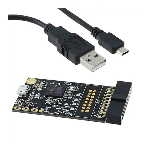
XMOS xCORE-200 Multi-channel Audio board Guide

USB Audio Design Guide
Document Number: XM0088546.1
Publication Date: 2016/5/12
XMOS © 2016, All Rights Reserved.

USB Audio Design Guide 2/110
SYNOPSIS
The XMOS USB Audio solution provides USB Audio Class compliant devices over USB 2.0 (high-
speed or full-speed). Based on the XMOS XS1 architecture, it supports USB Audio Class 2.0 and
USB Audio Class 1.0, asynchronous mode and sample rates up to 384kHz.
The complete source code, together with the free XMOS xTIMEcomposer development tools
and XCORE multi-core micro-controller devices allow the implementer to select the exact mix of
interfaces and processing required.
The XMOS USB Audio solution is deployed as a framework with reference design applications
extending and customising this framework. These reference designs have particular qualified
feature sets and an accompanying reference hardware platform.
This software design guide assumes the reader is familiar with the XC language and xCORE devices.
For more information see XMOS Programming Guide1.
The reader should also familiarise themselves with the XMOS USB Device Library
2
and the XMOS
USB Device Design Guide3
The reader should always refer to the supplied CHANGELOG and README files for known issues
etc in a specific release
1https://www.xmos.com/published/xmos-programming-guide
2http://www.xmos.com/published/xuddg
3https://www.xmos.com/zh/node/17007?page=9
XM0088546.1

USB Audio Design Guide 3/110
Table of Contents
1 Overview 5
2 Hardware Platforms 6
2.1 xCORE-200 Multi-Channel Audio Board ......................... 6
2.1.1 Analogue Input & Output .............................. 7
2.1.2 Digital Input & Output ................................ 7
2.1.3 MIDI ........................................... 7
2.1.4 Audio Clocking .................................... 7
2.1.5 LEDs, Buttons and Other IO ............................. 7
2.2 xCORE-200 Microphone Array Board ........................... 8
2.2.1 Microphones ...................................... 9
2.2.2 Analogue Output ................................... 9
2.2.3 Audio Clocking .................................... 10
2.2.4 Buttons, LEDs and Other IO ............................. 10
2.3 USB Multi-function Audio (MFA) Kit ............................ 12
2.4 U16 Multi-Channel USB Audio Kit ............................. 13
2.5 USB Audio 2.0 DJ Kit .................................... 14
2.6 USB Audio 2.0 Reference Design Board ......................... 14
2.7 USB Audio 2.0 Multichannel Reference Design Board ................. 15
3 Software Architecture 17
3.1 The USB Audio System Architecture ........................... 18
3.2 XMOS USB Device (XUD) Library .............................. 18
3.3 Endpoint 0: Management and Control .......................... 20
3.3.1 Enumeration ...................................... 20
3.3.2 Over-riding Standard Requests ........................... 21
3.3.3 Class Requests .................................... 21
3.4 Audio Endpoints (Endpoint Buffer and Decoupler) ................... 22
3.4.1 Endpoint Buffer .................................... 22
3.4.2 Decoupler ....................................... 23
3.4.3 Audio Buffering Scheme ............................... 23
3.4.4 Decoupler/Audio Core interaction ......................... 23
3.5 Audio Driver ......................................... 25
3.5.1 Port Configuration (xCORE Master) ......................... 27
3.5.2 Changing Audio Sample Frequency ......................... 28
3.6 Digital Mixer ......................................... 28
3.6.1 Control ......................................... 29
3.6.2 Host Control ...................................... 29
3.7 S/PDIF Transmit ....................................... 31
3.7.1 Clocking ........................................ 32
3.7.2 Usage .......................................... 33
3.7.3 Output stream structure ............................... 33
3.8 S/PDIF Receive ........................................ 33
3.8.1 Usage and Integration ................................ 34
3.9 ADAT Receive ........................................ 35
3.9.1 Integration ....................................... 36
3.10 External Clock Recovery (ClockGen) ........................... 36
3.11 MIDI .............................................. 37
3.12 PDM Microphones ...................................... 37
XM0088546.1

USB Audio Design Guide 4/110
3.13 Overview of PDM implemention .............................. 37
3.13.1 PDM Microphone Hardware Characteristics .................... 38
3.13.2 Integration of PDM Microphones into USB Audio ................. 39
3.14 Resource Usage ....................................... 40
4 Features & Options 41
4.1 Device Firmware Upgrade (DFU) .............................. 41
4.2 USB Audio Class Version Support ............................. 41
4.2.1 Driver Support ..................................... 42
4.2.2 Audio Class 1.0 Mode and Fall-back ........................ 42
4.3 Audio Controls via Human Interface Device (HID) ................... 43
4.4 Apple MFi compatibility .................................. 44
4.5 Audio Stream Formats ................................... 44
4.5.1 Audio Subslot ..................................... 45
4.5.2 Audio Sample Resolution .............................. 45
4.5.3 Audio Format ..................................... 46
4.6 DSD over PCM (DoP) .................................... 46
5 Programming Guide 48
5.1 Getting Started ....................................... 48
5.1.1 Building and Running ................................. 48
5.1.2 Installing the application onto flash ........................ 49
5.2 Project Structure ...................................... 50
5.2.1 Applications and Modules .............................. 50
5.3 Build Configurations .................................... 50
5.4 Validated Build Configurations .............................. 51
5.5 Configuration Naming Scheme .............................. 51
5.6 A USB Audio Application .................................. 51
5.6.1 Custom Defines .................................... 52
5.6.2 Configuration Functions ............................... 53
5.6.3 The main program .................................. 55
5.7 Adding Custom Code .................................... 58
5.7.1 Example: Changing output format ......................... 59
5.7.2 Example: Adding DSP to output stream ...................... 59
6 USB Audio Applications 61
6.1 USB Audio 2.0 Reference Design (L-Series) Application ................ 61
6.1.1 Port 32A ........................................ 62
6.1.2 Clocking ........................................ 63
6.1.3 HID ........................................... 64
6.1.4 Validated Build Options ............................... 65
6.2 The USB Audio 2.0 DJ Kit (U-Series) ............................ 66
6.2.1 Clocking and Clock Selection ............................ 67
6.2.2 CODEC Configuration ................................. 67
6.2.3 U-Series ADC ...................................... 67
6.2.4 HID Example ...................................... 67
6.2.5 Validated Build Options ............................... 68
6.3 The USB Audio 2.0 Multichannel Reference Design (L-Series) Software ....... 69
6.3.1 Clocking ........................................ 71
6.3.2 Validated Build Options ............................... 71
6.4 The Multi-function Audio Kit (U-Series) .......................... 72
6.4.1 Clocking and Clock Selection ............................ 72
XM0088546.1

USB Audio Design Guide 5/110
6.4.2 DAC and ADC Configuration ............................. 73
6.4.3 U-Series ADC ...................................... 73
6.4.4 HID Example ...................................... 73
6.4.5 Validated Build Options ............................... 76
6.5 The U-Series Multi-Channel USB Audio Kit ........................ 77
6.5.1 Clocking and Clock Selection ............................ 77
6.5.2 DAC and ADC Configuration ............................. 78
6.5.3 AudioHwInit() ..................................... 78
6.5.4 AudioHwConfig() ................................... 78
6.5.5 Validated Build Options ............................... 79
6.6 The xCORE-200 Multi-Channel Audio Board ....................... 79
6.6.1 Clocking and Clock Selection ............................ 80
6.6.2 DAC and ADC Configuration ............................. 80
6.6.3 AudioHwInit() ..................................... 81
6.6.4 AudioHwConfig() ................................... 81
6.6.5 Validated Build Options ............................... 82
6.7 The xCORE-200 Array Microphone Board ........................ 82
6.7.1 Clocking and Clock Selection ............................ 83
6.7.2 DAC Configuration .................................. 84
6.7.3 AudioHwInit() ..................................... 84
6.7.4 AudioHwConfig() ................................... 84
6.7.5 Mic Processing Example ............................... 84
6.7.6 Validated Build Options ............................... 85
7 API 86
7.1 Configuration Defines ................................... 86
7.1.1 Code location (tile) .................................. 86
7.1.2 Channel Counts .................................... 87
7.1.3 Frequencies and Clocks ............................... 87
7.1.4 Audio Class ...................................... 88
7.1.5 System Feature Configuration ............................ 89
7.1.6 USB Device Configuration .............................. 91
7.1.7 Stream Formats .................................... 92
7.1.8 Volume Control .................................... 96
7.1.9 Mixing Parameters .................................. 97
7.1.10 Power .......................................... 98
7.2 Required User Function Definitions ............................ 98
7.2.1 External Audio Hardware Configuration Functions ................ 98
7.2.2 Audio Streaming Functions ............................. 99
7.2.3 Host Active ....................................... 99
7.2.4 HID Controls ......................................100
7.3 Component API .......................................100
8 Frequently Asked Questions 110
XM0088546.1

1 Overview
XM0088546.1

USB Audio Design Guide 7/110
Functionality
Provides USB interface to audio I/O.
Supported Standards
USB USB 2.0 (Full-speed and High-speed)
USB Audio Class 1.04
USB Audio Class 2.05
USB Firmware Upgrade (DFU) 1.16
USB Midi Device Class 1.07
Audio I2S/TDM
S/PDIF
ADAT
Direct Stream Digital (DSD)
PDM Microphones
MIDI
Supported Sample Frequencies
44.1kHz, 48kHz, 88.2kHz, 96kHz, 176.4kHz, 192kHz, 352.8kHz, 384kHz
Supported Devices
XMOS Devices xCORE-200 Series
XS1 L-Series
XS1 U-Series
XS1 G-Series (Not recommended for
new designs)
Requirements
Development Tools xTIMEcomposer Development Tools
v14 or later
USB External ULPI USB Phy (If using XS1
G/L-Series)
Audio External audio DAC/ADC/CODECs
(and required supporting
componentry) supporting I2S/TDM
Boot/Storage Compatible SPI Flash device
Licensing and Support
Reference code provided without charge under license from XMOS.
Please visit http://www.xmos.com/support/contact for support.
Reference code is maintained by XMOS Limited.
4http://www.usb.org/developers/devclass_docs/audio10.pdf
5http://www.usb.org/developers/devclass_docs/Audio2.0_final.zip
6http://www.usb.org/developers/devclass_docs/DFU_1.1.pdf
7http://www.usb.org/developers/devclass_docs/midi10.pdf
XM0088546.1

2 Hardware Platforms
IN THIS CHAPTER
·xCORE-200 Multi-Channel Audio Board
·xCORE-200 Microphone Array Board
·USB Multi-function Audio (MFA) Kit
·U16 Multi-Channel USB Audio Kit
·USB Audio 2.0 DJ Kit
·USB Audio 2.0 Reference Design Board
·USB Audio 2.0 Multichannel Reference Design Board
The following sections describe the hardware platforms that support development
with the XMOS USB Audio software framework.
2.1 xCORE-200 Multi-Channel Audio Board
The XMOS xCORE-200 Multi-channel Audio board
8
(XK-AUDIO-216-MC) is a com-
plete hardware and reference software platform targeted at up to 32-channel USB
and networked audio applications, such as DJ decks and mixers.
The Multichannel Audio Platform hardware is based around the XE216-512-TQ128
multicore microcontroller; an dual-tile xCORE-200 device with an integrated High
Speed USB 2.0 PHY, RGMII (Gigabit Ethernet) interface and 16 logical cores deliver-
ing up to 2000MIPS of deterministic and responsive processing power.
Exploiting the flexible programmability of the xCORE-200 architecture, the Multi-
channel Audio Platform supports either USB or network audio source, streaming 8
analogue input and 8 analogue output audio channels simultaneously - at up to
192kHz. Ideal for mixing two sources and providing main and headphone monitor
output feeds.
For full details regarding the hardware please refer to xCORE-200 Multichannel
Audio Platform Hardware Manual9.
The reference board has an associated firmware application that uses the USB
Audio 2.0 software reference platform. Details of this application can be found in
section §6.6.
8https://www.xmos.com/support/boards?product=18334
9https://www.xmos.com/support/boards?product=18334&component=18687
XM0088546.1

USB Audio Design Guide 9/110
2.1.1 Analogue Input & Output
A total of eight single-ended analog input channels are provided via 3.5mm stereo
jacks. Each is fed into a CirrusLogic CS5368 ADC. Similarly a total of eight single-
ended analog output channels are provided. Each is fed into a CirrusLogic CS4384
DAC.
The four digital I2S/TDM input and output channels are mapped to the xCORE
input/outputs through a header array. The jumper allows channel selection when
the ADC/DAC is used in TDM mode
2.1.2 Digital Input & Output
Optical and coaxial digital audio transmitters are used to provide digital audio
input output in formats such as IEC60958 consumer mode (S/PDIF) and ADAT. The
output data streams from the xCORE-200 are re-clocked using the external master
clock to synchronise the data into the audio clock domain. This is achieved using
simple external D-type flip-flops.
2.1.3 MIDI
MIDI I/O is provided on the board via a standard Gameport connector. The signals
are buffered using 5V line drivers and are then connected to 1-bit ports on the
xCORE-200, via a 5V to 3.3V buffer.
2.1.4 Audio Clocking
A flexible clocking scheme is provided for both audio and other system services.
In order to accommodate a multitude of clocking options, the low-jitter master
clock is generated locally using a frequency multiplier PLL chip. The chip used is a
Phaselink PL611-01, which is pre-programmed to provide a 24MHz clock from its
CLK0 output, and either 24.576 MHz or 22.5792MHz from its CLK1 output.
The 24MHz fixed output is provided to the xCORE-200 device, as the main pro-
cessor clock. It also provides the reference clock to a Cirrus Logic CS2100, which
provides a very low jitter audio clock from a synchronisation signal provided from
the xCORE-200.
Either the locally generated clock (from the PL611) or the recovered low jitter clock
(from the CS2100) may be selected to clock the audio stages; the xCORE-200, the
ADC/DAC and Digital output stages.
2.1.5 LEDs, Buttons and Other IO
An array of 4*4 green LEDs, 3 buttons and a switch are provided for general
purpose user interfacing. The LED array is driven by eight signals each controlling
one of 4 rows and 4 columns.
A standard XMOS xSYS interface is provided to allow host debug of the board via
JTAG.
XM0088546.1

USB Audio Design Guide 10/110
2.2 xCORE-200 Microphone Array Board
The XMOS xCORE-200 Microphone Array board
10
(XK-USB-MIC-UF216) is design
available from XMOS based on a dual-tile XMOS xCORE-200 device.
The board integrates the following building blocks: multiple omni-directional
microphones, on-board low-jitter clock sources, configurable user input buttons
and a USB2.0 device for connectivity. making it an ideal platform for a range of
multichannel microphone aggregation products.
The board is powered by an XUF216-512 xCORE-200 multicore microcontroller.
This device has sixteen 32bit logical cores that deliver up to 2000MIPS completely
deterministically. In addition the XUF216 has powerful DSP properyies with native
32bit/64 instructions delivering up to 1000MMACS.
Figure 1shows the block layout of the xCORE-200 Microhone Array board.
xCORE
XUF216
Ethernet
PHY
LAN8710A
RJ45
25MHz
TILE CLK to xCore
DAC-MCLK
PLL CLK
Device
CS2100
BUFFERMCLK 24.576
MHz
SMI
MDI
DAC
CS43L21
MEMS mic
AKU441
I2S
I2C
HP
MII
USB
Type-B
1v3v3 2v5
XTAG(J2)
MIC0
MIC4
MIC3
MIC2
MIC1
MIC5
MIC6
MIC-DATA[6:0]
MIC-CLK
Buffer
MIC CLK[6:0]
JTAG
LEDs
BUFFER
PUSH BUTTON
D-FF
3.5mm Jack
USB diff pair
24MHz
Figure 1:
xCORE-200
Microphone
Array Board
Block
Diagram
For full details regarding the hardware please refer to xCORE Microphone Array
Hardware Manual11.
The reference board has an associated firmware application that uses the USB
Audio 2.0 software reference platform. Details of this application can be found in
section §6.7.
10https://www.xmos.com/support/boards?product=20258
11https://www.xmos.com/download/private/xCORE-Microphone-Array-Hardware-Manual%281v1%29.pdf
XM0088546.1

USB Audio Design Guide 11/110
2.2.1 Microphones
The xCORE Microphone Array board features 7 MEMS microphones with PDM (Pulse
Density Modulation) output.
Figure 2shows the microphone arrangement on the board.
MIC6 MIC1
MIC2MIC5 MIC0
A
B
D
xCORE-200
XUF216
C
MIC4 MIC3
Figure 2:
xCORE-200
Microphone
Array Board
Microphone
Arrangement
2.2.2 Analogue Output
As well at 7 PDM microphones the board also provides a stereo DAC (CS43L21)
with integrated headphone amplifier. The CS43L21 is connected to the xCORE-200
through an I2S interface and is configured using an I2C interface.
XM0088546.1

USB Audio Design Guide 12/110
2.2.3 Audio Clocking
The board provides a low-jitter clock-source, an 24.576MHz oscillator, to serve as
reference clock to the CS2100-CP (Cirrus Logic) Fractional-N PLL (U22).
The CS2100 generates a low-jitter output signal that is distributed to the xCORE-
200 device and DAC. The CS2100 device is configured using the I2C interface.
2.2.4 Buttons, LEDs and Other IO
The board has 13 LEDs that are controlled by the xCORE-200 GPIO. The layout of
the LEDs is shown in Figure 3.
MIC6
MIC1
MIC2
MIC5
D14
D2
D3
D4
D5
D6
D7D8
D9
D10
D11
D12
D13
A B D
xCORE-200
XUF216
C
MIC4
MIC3
Figure 3:
xCORE-200
Microphone
Array Board
LED
Arrangement
LED 0 to LED 11 (D2-D13) are positioned around the edge of the board, one
each side of every microphone. LED 12 (D14) is positioned next to the middle
microphone.
XM0088546.1

USB Audio Design Guide 13/110
A green LED (PGOOD) by the USB connector indicates a 3V3 power good signal.
Four general purpose push-button switches are provided. When pressed, each
button creates a connection from the I/O to GND.
A standard XMOS xSYS interface (J2) is provided to allow host debug of the board
via JTAG.
The board also includes Ethernet conextivity, however, this is outside the scope of
this documentation.
XM0088546.1

USB Audio Design Guide 14/110
2.3 USB Multi-function Audio (MFA) Kit
It is not recommended to use this hardware as a basic for a new design
The XMOS Multi-function Audio kit
12
(XK-USB-AUDIO-U8-2C-AB) is a hardware refer-
ence design available from XMOS based on a single tile XMOS U-series device.
·
A main board which includes the XMOS U-series device and all audio
hardware
·A “USB Slice” board which contains USB connectivity
The separate USB slice board allows flexibility in the connection method to the USB
audio source/sink as well as other functionality such as 3rd party authentication
ICs and any required USB switching. This also means the XMOS device can be used
as a USB device or host using the same main board.
This document addresses the combination of the main board with the USB AB slice
(part numbers XK-USB-AUDIO-U8-2C and XA-SK-USB-AB respectively). This provides
a standard USB Audio device hardware configuration using the B socket on the USB
AB slice.
XMOS
XS1-U8A-64
24 bit 192kHz
+ DSD
Stereo Audio
DAC
CS4392
24 bit 192kHz
Stereo Audio
ADC
CS4392
I2S
I2S
Audio Master
Clock PLL
24. 76 MHz
Or
22. 792 MHz
& 24MHz
MCLK
FSEL
Stereo
Differential to
Single Ended
Active LPF
Stereo
Single Ended
Active LPF
3. mm
Stereo
TRS Jack
3. mm
Stereo
TRS Jack
Gate SPDIF RCA
Socket
Buffer Isolator &
Buffer
MIDI
MIDI
Pin DIN
MIDI TX
Pin DIN
MIDI RX
MUX
4Mbit
Flash
CS
SPI
2 Position
Switch
&
2 x Push
Buttons
2 x User
LEDs
USB
Slice
Connector
PCIE 36
Socket
USB
High Speed
I2C
GPIO
24MHz
XSYS
Debug
Connector
JTAG
XSCOPE
Link
12V DC
3A
Cent +ve
Connector
12V to V
DCDC
12V
Over Voltage
Protection
V
Over Current
Protection
Switch
VBUS
OUT
EN
Preferential
V OR
VBUS
IN
VBUS IN
Preferential
V OR
V
Charge Pump V Analogue Audio
Dual
3V3 LDO 3V3 IO
3V3 ADC 3V3 High
Side Switch
3V3 Analogue Audio
EN
System V
Figure 4:
Multi-
function
Audio Kit
Block
Diagram
The core board includes a U-Series device with integrated USB PHY, a stereo DAC
(with support for Direct Stream Digital) and a stereo ADC. Both ADC and DAC
12http://www.xmos.com/products/reference-designs/mfa
XM0088546.1

USB Audio Design Guide 15/110
support sample frequencies up to 192kHz. As well as analogue channels the main
board also has MIDI input and output connectors and a COAX connector for S/PDIF
output.
In addition the main board also includes two LEDs, two buttons and one two-
position switch for use by the user application.
2.4 U16 Multi-Channel USB Audio Kit
It is not recommended to use this hardware as a basic for a new design
The XMOS U16 Multi-Channel USB Audio kit
13
is a hardware development platform
available from XMOS based on a dual tile XMOS U-series device.
·
A sliceKIT core board which includes the XMOS U-series device (XP-SKC-U16)
·A “USB Slice” board which contains USB connectivity (XA-SK-USB-AB)
·
A double-slot slice card including audio hardware and connectors (XA-SK-
AUDIO8)
The separate USB slice board allows flexibility in the connection method to the USB
audio source/sink as well as other functionality such as 3rd party authentication
ICs and any required USB switching. This also means the XMOS device can be used
as a USB device or host using the same main board.
This document addresses the combination of the main board with the USB AB
slice (part numbers XP-SKC-U16 and XA-SK-USB-AB respectively). This provides a
standard USB Audio device hardware configuration using the B socket on the USB
AB slice.
The core board includes a U-Series device with integrated USB PHY and required
supporting componentry.
Please note, for correct operation the following core-board jumper settings are
required:
·J14 (DIA/ALT) should be set to ALT
·J15 (D12 XOVER) should be set to ON
The double-slot audio slice (XA-SK-AUDIO8) includes separate multi-channel DAC
and ADC providing 8 channels of both analogue output and input. Both DAC and
ADC devices support sample frequencies up to 192kHz with the DAC supporting
Direct Stream Digital (DSD).
As well as analogue channels the audio-slice also has MIDI input and output
connectors and both COAX and optical connectors for digital output.
Additionally the slice also includes an LED matrix and three push-buttons for use
by the user application.
13http://www.xmos.com/usbaudio16mc
XM0088546.1

USB Audio Design Guide 16/110
2.5 USB Audio 2.0 DJ Kit
This hardware should not be used for the basis of a new design.
The XMOS USB Audio 2.0 DJ kit (XR-USB-AUDIO-2.0-4C)
14
is a hardware reference
design available from XMOS based on the XMOS U8 device.
The DJ naming simply comes from the fact the board has 4 input and 4 output
audio channels - a common configuration for a DJ controller.
The kit is made up of two boards a “core” board and an “audio slice” board. Part
numbers XP-SKC-SU1 and XA-SK-AUDIO respectively.
The core board includes a U-Series device with integrated USB PHY. The audio slice
board is equipped with two stereo audio CODECs giving 4 channels of input and 4
channels of output at sample frequencies up to 192kHz.
In addition to analogue channels the audio slice board also has MIDI input and
output connectors and a COAX connector for S/PDIF output.
2.6 USB Audio 2.0 Reference Design Board
This hardware should not be used for the basis of a new design.
The USB Audio 2.0 Reference Design
15
is a stereo hardware reference design
available from XMOS based on an XMOS L8 device (previously named L1). The
diagram in Figure 5shows the block layout of the USB Audio 2.0 Reference Design
board. The main purpose of the XS1 L-Series device is to provide a USB Audio
interface to the USB PHY and route the audio to the audio CODEC and S/PDIF output.
Note, although the software supports MIDI, there are no MIDI connectors on the
board.
For full hardware details please refer to the USB Audio 2.0 Ref Design XS1-L1
Hardware Manual16.
The reference board has an associated firmware application that uses the USB
Audio 2.0 software reference platform. Details of this application can be found in
section §6.1.
14https://www.xmos.com/support/boards?product=15404
15https://www.xmos.com/support/boards?product=14772
16https://www.xmos.com/published/usb-audio-20-ref-design-xs1-l1-hardware-manual
XM0088546.1

USB Audio Design Guide 17/110
13MHz
Oscillator
USB
Series B
Receptacle
1.8V LDO
3.3V LDO
1.0V DC-DC
4.3V LDO
User
LEDs
Push-button
Switches Audio Master
Clock Oscillator
Produces
24.576MHz
or
11.2896MHz
USB
Transceiver
USB3318
Passive
LPF
‘-244
Stereo
TRS Jack
‘-244
Stereo
TRS Jack
Passive
LPF
24 bit 192kHz
Stereo Audio
CODEC
CS4270
USB
High Speed
480Mb/s
+5V VBus
8’.’
Tile
Supply
CODEC
Analogue
Supply
ULPI I2S
Analog Out
1Vrms at
Full Scale
Analog In
2Vrms at
Full Scale
JTAG SPI MCLK
S/PDIF
XSYS
Debug
1MBit
FLASH Resync Optical
Digital Audio
Transmitter
Figure 5:
USB Audio
2.0 Reference
Design Block
Diagram
2.7 USB Audio 2.0 Multichannel Reference Design Board
This hardware should not be used for the basis of a new design.
The USB Audio 2.0 Multichannel Reference Design (XR-USB-AUDIO-2.0-MC)
17
is a
hardware reference design available from XMOS based on the XMOS L16 device
(previously named L2)
Figure 6shows the block layout of the USB Audio 2.0 Multichannel Reference
Design board.
The board supports six analogue inputs and eight analogue outputs (via a CS4244
CODEC), digital input and output (via coax and optical connectors) and MIDI input
and output. For full details please refer to USB Audio 2.0 Reference Design, XS1-L2
Edition Hardware Manual18.
The reference board has an associated firmware application that uses the USB
Audio 2.0 software reference platform. Details of this application can be found in
section §6.3.
17https://www.xmos.com/support/boards?product=14771
18https://www.xmos.com/download/public/USB-Audio-2.0-MC-Hardware-Manual%281.6%29.pdf
XM0088546.1

3 Software Architecture
IN THIS CHAPTER
·The USB Audio System Architecture
·XMOS USB Device (XUD) Library
·Endpoint 0: Management and Control
·Audio Endpoints (Endpoint Buffer and Decoupler)
·Audio Driver
·Digital Mixer
·S/PDIF Transmit
·S/PDIF Receive
·ADAT Receive
·External Clock Recovery (ClockGen)
·MIDI
·PDM Microphones
·Overview of PDM implemention
·Resource Usage
The following sections describe the software architecture of the XMOS USB Audio
framework.
XMOS USB Audio solutions are provided as a framework with reference design
applications customising and extending this framework to provide the required
functionality. These applications execute on a reference hardware platform.
XM0088546.1

USB Audio Design Guide 20/110
3.1 The USB Audio System Architecture
The XMOS USB Audio platform consists of a series of communicating components.
Every system is required to have the shared components listed in Figure 7.
Component Description
XMOS USB Device Driver (XUD) Handles the low level USB I/O.
Endpoint 0 Provides the logic for Endpoint 0 which handles
enumeration and control of the device including DFU
related requests.
Endpoint buffer Buffers endpoint data packets to and from the host.
Decoupler Manages delivery of audio packets between the
endpoint buffer component and the audio components.
It can also handle volume control processing.
Audio Driver Handles audio I/O over I2S and manages audio data
to/from other digital audio I/O components.
Figure 7:
Shared
Components
In addition Figure 8shows components that can be added to a design:
Component Description
Mixer Allows digital mixing of input and output channels. It can also
handle volume control instead of the decoupler.
S/PDIF Transmitter Outputs samples of an S/PDIF digital audio interface.
S/PDIF Receiver Inputs samples of an S/PDIF digital audio interface (requires the
clockgen component).
ADAT Receiver Inputs samples of an ADAT digital audio interface (requires the
clockgen component).
Clockgen Drives an external frequency generator (PLL) and manages
changes between internal clocks and external clocks arising from
digital input.
MIDI Outputs and inputs MIDI over a serial UART interface.
PDM Microphones Receives PDM data from microphones and performs PDM to PCM
conversion
Figure 8:
Optional
Components
Figure 9shows how the components interact with each other. The green circles
represent cores with arrows indicating inter-core communications.
This section will now examine these components in further detail.
3.2 XMOS USB Device (XUD) Library
All low level communication with the USB host is handled by the XMOS USB Device
(XUD) library.
The
XUD_Manager()
function runs in its own core and communicates with endpoint
cores though a mixture of shared memory and channel communications.
XM0088546.1
Other manuals for xCORE-200 Multi-channel Audio board
1
Table of contents
Other XMOS Computer Hardware manuals

XMOS
XMOS XK-XMP-64 User manual

XMOS
XMOS XS1-L1 User manual

XMOS
XMOS xCORE-Analog sliceKIT User manual

XMOS
XMOS SliceKit User manual

XMOS
XMOS XVF3800 User manual

XMOS
XMOS XTAG-2 User manual

XMOS
XMOS XS1-L2 User manual

XMOS
XMOS XC-1A User manual

XMOS
XMOS VocalFusion XVF3510 User manual

XMOS
XMOS xTAG v3.0 User manual
Popular Computer Hardware manuals by other brands

Artesyn
Artesyn RTM-ATCA-9305 IO Installation and use

GE
GE ATS1290 manual

Texas Instruments
Texas Instruments OMAP5912 reference guide

Mellanox Technologies
Mellanox Technologies ConnectX-3 MCX312A-XCBT user manual

SIIG
SIIG SoundWave 5.1 PCI-LP Quick installation guide

Acrosser Technology
Acrosser Technology AR-B1653 user guide