XMOS SliceKit GPIO User guide

SliceKit GPIO Example Applications
REV A
Publication Date: 2012/10/23
XMOS © 2012, All Rights Reserved.

SliceKit GPIO Example Applications 2/24
Table of Contents
1 Overview 3
2 Evaluation Platforms 4
2.1 Recommended Hardware ................................... 4
2.2 Example Applications ..................................... 4
2.2.1 app_slicekit_simple_demo .............................. 4
2.2.2 app_slicekit_com_demo ............................... 4
3 Programming Guide 6
3.1 Simple Demo .......................................... 6
3.1.1 Structure ........................................ 6
3.1.2 API ........................................... 6
3.1.3 Usage and Implementation ............................. 7
3.2 COM Port Demo ........................................ 9
3.2.1 Structure ........................................ 9
3.2.2 API ........................................... 9
3.2.3 Usage and Implementation ............................. 10
REV A

1 Overview
This document covers two example applications that demonstrate various features
of the XA-SK-GPIO Slice Card including the ADC, LEDs, UART connector and buttons,
the I2C master xSOFTip component, as well as various basic features of the xCORE
processor.
Low level details of how the application is implemented are covered here, with
information about how to modify and experiment with them.
For getting started instructions for both applications, please refer to their respective
Quick Start guides.
REV A

2 Evaluation Platforms
IN THIS CHAPTER
·Recommended Hardware
·Example Applications
2.1 Recommended Hardware
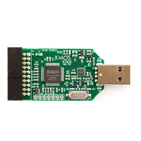
This application may be evaluated using the Slicekit Modular Development Platform,
available from digikey. Required board SKUs are:
·
XP-SKC-L2 (Slicekit L2 Core Board) plus XA-SK-GPIO plus XA-SK-XTAG2 (Slicekit
XTAG adaptor) plus XTAG2 (debug adaptor),
2.2 Example Applications
2.2.1 app_slicekit_simple_demo
This application has the following features:
·
module_i2c_master from the xSOFt ip library is used to access the external ADC,
which is equipped with an external linearised thermistor circuit for temperature
sensing.
·
simple code to print the recorded temperature to the XDE debug console on the
press of one of the Slice Card buttons
·simple code to cycle through the 4 LEDs each time the other button is pressed.
·
demonstrates use of XC select statements for handling multiple concurrent
inputs
·demonstrates basic usage of XCore ports
2.2.2 app_slicekit_com_demo
This application extends the simple demo to provides the following functionality
(all options are dynamically reconfigurable via the APIs for app_slicekit_com_demo
application):
· · Baud Rate: 150 to 115200 bps
·Parity: None, Mark, Space, Odd, Even
·Stop Bits: 1,2
·
Data Length: 1 to 30 bits (Max 30 bits assumes 1 stop bit and no parity)
REV A

3 Programming Guide
IN THIS CHAPTER
·Simple Demo
·COM Port Demo
3.1 Simple Demo
3.1.1 Structure
All of the files required for operation are located in the
app_sk_gpio_simple_demo/src
directory.
The files that are need to be included for use of this component in an application are:
File Description
common.h Header file for API interfaces and Look up tables for thermistor.
main.xc Main file which implements the demo functionality
3.1.2 API
void app_manager(chanend c_uartTX,
chanend c_chanRX,
chanend c_process,
chanend c_end)
Polling uart RX and push button switches and send received commands to pro-
cess_data thread.
This function has the following parameters:
c_uartTX Channel to Uart TX Thread
c_chanRX Channel to Uart RX Thread
c_process Channel to process data Thread
c_end Channel to read data from process thread
int linear_interpolation(int adc_value)
Calculates temperatue based on linear interpolation.
This function has the following parameters:
adc_value int value read from ADC
REV A

SliceKit GPIO Example Applications 7/24
This function returns:
Returns linear interpolated Temperature value
int read_adc_value()
Read ADC value using I2C.
This function returns:
Returns ADC value
3.1.3 Usage and Implementation
The port declaration for the LEDs, Buttons and I2C are declared as below. LEDs and Buttons use 4
bit ports and I2C uses 1 bit port for SCL(I2c Clock) and SDA (I2C data).
on st dcore [ C ORE _NU M ]: out port p _led = X S1_P ORT_ 4A ;
on stdc ore [ CO RE_NU M ]: port p_ POR T_B UT_ 1 = XS1 _PO RT_ 4C ;
on std core [ CO RE_NU M ]: struct r_i 2c i 2c On e = {
XS1_PORT_1F ,
XS1_PORT_1B ,
1000
};
The app_manager API writes the configuration settings information to the ADC as shows below.
i2 c_ mas te r_ wr ite _r eg (0 x28 , 0 x00 , data , 1, i2cO ne ) ; // Write co n fi gur at ion in for mat io n to
>ADC
The select statement in the app_manager API selects one of the two cases in it, checks if there is
IO event or timer event. This statement monitors both the events and executes which ever event
is occurred first. The select statement in the application is listed below. The statement checks if
there is button press or not. If there is button press then it looks if the button state is same even
after 200msec. If the buton state is same then it recognises as an valid push.
select
{
case bu tton => p_ PO RT _B UT _1 when pi nsn eq ( bu tton _pr es s_ 1 ): > bu tt on _pr e ss_ 1 : //
>chec ks if any b utton is p ress ed
button=0;
t :> t im e ;
brea k ;
case ! bu tt on = > t when t im er af te r ( time + d eb ou nce _t im e ): > vo id : // w ai ts for 2 0 ms and
>chec ks if the same b utto n is p r ess ed or not
p_P ORT_ BU T_1 : > b utt on _p re ss_ 2 ;
if(button_press_1==button_press_2)
if ( bu tt on_ pr ess _1 == BU TT ON _PR ES S_ VA LUE ) // Butt on 1 is pre sse d
{
pr in ts tr ln ( " But ton 1 Pr es se d ") ;
p_led <:( led _v al ue ) ;
le d_ va lue = l ed_ val ue < <1 ;
le d_ va lu e | =0 x01 ;
REV A

SliceKit GPIO Example Applications 8/24
le d_ va lu e = l ed _v al ue & 0 x0 F ;
if ( l ed _v a lu e = = 1 5)
{
le d_ va lu e =0 x 0E ;
}
}
if ( b u tt o n_ p re s s_ 1 = = B UT T ON _ PR ES S_ V AL U E - 1) // B ut to n 2 i s p re s se d
{
data1 [ 0]=0; d ata1 [1 ]=0;
i2 c_m ast er _r x (0 x28 , data1 , 2 , i 2cO ne ) ; / / Re ad ADC va lu e u si ng I2C
>read
pr in tst rl n ( " Re ad ing T emp er at ur e valu e .... " );
dat a1 [ 0] = d at a1 [ 0] &0 x 0F ;
adc _v al ue =( d ata1 [0] < <6) |( d ata 1 [1] > >2) ;
pri nt st r (" T emp er at ur e is :" );
pri nt in tl n ( lin ear _i nte rp ola tio n ( ad c_ va lu e ));
}
button=1;
brea k ;
}
After recognising the valid push then it checks if Button 1 is pressed or Button 2 is pressed. IF
Button 1 is pressed then, the application reads the status of LEDs and shift the position of the
LEDs to left by 1. If Button 2 is pressed, then the applciation reads the contents of ADC register
using I2C read instruction and input the ADC value to linear interpolation function as shown
below.
int l in ea r_ in t er p ol at io n ( in t a dc _v alu e )
{
int i=0 ,x1 , y1 , x2 , y2 , te mper ;
whil e ( adc _va lue < T EM PE RA TU RE _LU T [i ] [1] )
{
i ++;
}
//:: Fo r mul a start
// C a lc u la t in g L in ea r i nt e rp ol a ti o n us in g t he f or m ul a y = y1 + (x - x1 ) * ( y2 - y 1 ) /( x2 - x1 )
//::Formula
x1 = TE MPE RA TU RE_ LU T [i - 1][ 1];
y1 = TE MPE RA TU RE_ LU T [i - 1][ 0];
x2 = TE MPE RA TU RE_ LU T [i ][ 1 ];
y2 = TE MPE RA TU RE_ LU T [i ][ 0 ];
t em pe r = y 1 +(( ( a dc _v al ue - x 1 ) *( y2 - y1 ) ) /( x 2 - x1 ) ) ;
retu rn te m per ;// Re turn Tem per atu re v alue
}
The linear intepolation function calculates the linear interpolation value using the following
formula and returns the temperature value from temperature look up table.
// C a lc u la t in g L in ea r i nt e rp ol a ti o n us in g t he f or m ul a y = y1 + (x - x1 ) * ( y2 - y 1 ) /( x2 - x1 )
int TEM PE RAT UR E_ L UT [][2 ]= // T emp era tu re Look up t able
{
{ -10 ,845} ,{ -5 ,80 8 } ,{0 ,765} ,{5 ,718} , {1 0 ,6 68 } ,{ 15 , 61 4} ,{20 ,559} ,{25 ,5 04 } ,{ 30 , 45 0} , {3 5 ,399} ,
>
{40 ,352} , {45 ,308} ,{ 50 ,269} ,{5 5 ,233} ,{60 , 2 02}
REV A
SliceKit GPIO Example Applications 9/24
};
3.2 COM Port Demo
3.2.1 Structure
All of the files required for operation are located in the
app_slicekit_simple_demo/src
directory.
The files that are need to be included for use of this component in an application are:
File Description
common.h Header file for API interfaces and Look up tables for thermistor. FIXME -
what about the uart
main.xc Main file which implements the demo functionality
3.2.2 API
void app_manager(chanend c_uartTX,
chanend c_chanRX,
chanend c_process,
chanend c_end)
Polling uart RX and push button switches and send received commands to pro-
cess_data thread.
This function has the following parameters:
c_uartTX Channel to Uart TX Thread
c_chanRX Channel to Uart RX Thread
c_process Channel to process data Thread
c_end Channel to read data from process thread
void process_data(chanend c_process, chanend c_end)
process received data to see if received data is valid command or not Polling
switches to see for button press
This function has the following parameters:
c_process Channel to receive data from app manager Thread
c_end Channel to communicate to app manager thread
void uart_tx_string(chanend c_uartTX, unsigned char message[100])
Transmits byte by byte to the UART TX thread for an input string.
This function has the following parameters:
REV A

SliceKit GPIO Example Applications 10/24
c_uartTX Channel to receive data from app Uart TX Thread
message Buffer to store array of characters
int linear_interpolation(int adc_value)
Calculates temperatue based on linear interpolation.
This function has the following parameters:
adc_value int value read from ADC
This function returns:
Returns linear interpolated Temperature value
int read_adc_value()
Read ADC value using I2C.
This function returns:
Returns ADC value
3.2.3 Usage and Implementation
The port declaration for the LEDs, Buttons, I2C and UART are declared as below. LEDs and Buttons
uses 4 bit ports, UART uses 1 bit ports both for Transmit and Receive and I2C uses 1 bit port for
SCL(I2c Clock) and SDA (I2C data).
# define CO RE_ NUM 1
# define B UTT ON _PRE SS_V AL UE 2
on stdc or e [ CO RE_ NU M ] : bu ff ere d in port :1 p_rx = X S1_ PORT _1 G ;
on stdc or e [ CO RE_ NU M ] : out port p_tx = X S1_ POR T_1 C ;
on st dc ore [ C ORE _NU M ]: port p_ le d = XS1_ POR T_4A ;
on st dc or e [ COR E_ NUM ]: port p_b utt on1 = X S1_P ORT _4C ;
on std core [ CO RE_NU M ]: struct r_i 2c i 2c On e = {
XS1_PORT_1F ,
XS1_PORT_1B ,
1000
};
The app_manager API writes the configuration settings information to the ADC as shows below.
i2 c_ mas te r_ wr ite _r eg (0 x28 , 0 x00 , i2 c_reg iste r , 1 , i 2cOn e ) ; // Con fig ure ADC by w riti ng the
>set tin g s to r egi ste r
The select statement in the app_manager API selects one of the three cases in it, checks if there
is IO event or timer event or any event on the Uart Receive pin. This statement monitors all the
events and executes which ever event is occurred first. The select statement in the applciation
is listed below. The statement checks if there is button press or availability of data on the Uart
Receive pin. If there is button press then it looks if the button state is same as even after 200msec.
If the buton state is same then it recognises as a valid push. If there is data on the Uart Receive
REV A

SliceKit GPIO Example Applications 11/24
pin the it echoes the data back to the uart Transmit pin until
>
character is received in the input
data.
select
{
case c_ en d :> d at a :
c_e nd : > da ta ;
if ( data == BU TTON _1 ) // Cy cle LE Ds on b utto n 1 press
{
pr in ts tr ln ( " Bu tto n 1 Pre ss ed " );
p_led <:( l ed _v al ue ) ;
le d_ va lue = l ed_ val ue < <1;
if ( le d_v alu e == 16) // If LED val ue is 16 the n
>ass i gns LED va l ue to 1 w hich c ycles LE D s by
>butt on pres s
{
le d_ va lu e =0 x 01 ;
}
}
if ( data == B UTT ON_ 2 ) // Dis pla ys T em per atu re on co n sol e if
>Butt on 2 is pre ssed
{
a dc _ va lu e = r e ad _a d c_ va l ue () ;
dat a_ ar r [0]=( li nea r_ int er pol ati on ( a dc _v al ue ) );
pri nt st r (" T emp er at ur e is :" );
pri nt in t ( li nea r_ int er pol ati on ( a dc _v al ue ) );
pri nt st rl n (" C ");
}
brea k ;
case u ar t_ rx _g et _b yt e_ byr ef ( c _uart RX , r xState , buf fe r ):
//:: Co m man d start
if ( b uf fe r == '>') // IUF re cei ve d data is '>'character
>then ex p ect s cmd to end t er into co mman d mode
{
j =0;
ua rt _r x_ ge t_ by te _b yr ef ( c _u artR X , r xState , buf fe r )
>;
c md _ rc v bu ff e r [ j ]= b uf f er ;
if (( c md _r cv bu ffe r [j ] == 'C') || ( cm d_ rc vbuf fe r [j]
>== 'c') ) // C he ck s i f r ec e iv e d d at a is 'C'or
>'c'
{
j ++;
ua rt _r x_ ge t_ by te _b yr ef ( c _u artR X , r xState ,
>buffer);
c md _ rc v bu ff e r [ j ]= b uf f er ;
if (( c md _r cv bu ffe r [j ] == 'm') || (
>c md _ rc v bu f fe r [ j ] == 'M') ) // C he ck s i f
>rec eiv e d data is 'M'or 'm'
{
j ++;
ua rt _r x_ ge t_ by te _b yr ef ( c _u artR X ,
>rxState , b uf fe r );
c md _ rc v bu ff e r [ j ]= b uf f er ;
if (( c md _r cv buf fe r [ j] == 'D') | | (
>c md _ rc v bu f fe r [ j ] == 'd') ) / /
>Chec ks if re c eiv ed data is '
>D'or 'd'
{
REV A

SliceKit GPIO Example Applications 12/24
uart_tx_send_byte(
>c_uartTX , '\r ') ;
uart_tx_send_byte(
>c_uartTX , '\n ') ;
ua rt_ tx _s tr in g ( c_ uar tTX ,
>CONSOLE_MESSAGES[0])
>;
COMMAND_MODE=1; //
>act iva tes c omma nd
>mode as re ceiv ed
>data is '>cmd '
uart_tx_send_byte(
>c_uartTX , '\r ') ;
uart_tx_send_byte(
>c_uartTX , '\n ') ;
uart_tx_send_byte(
>c_uartTX , '>'); //
>dis pla y s '>'if
>com m and m o de is
>activated
}
else
{
uart_tx_send_byte(
>c_uartTX , '>');
for ( i nt i = 0; i <3; i ++)
uart_tx_send_byte
>(c_uartTX ,
>cmd_rcvbuffer
>[ i ]) ; // if
>rec eiv e d dta
>is not 'c'
>dis pla y s
>back the
>rec eiv e d
>data
}
}
else
{
ua rt_ tx _s en d_ by te ( c_u artTX , '>') ;
>// if re ce iv ed data is not '
>m'dis pla y s the rec eiv e d
>data
for ( i nt i = 0; i <2; i ++)
uart_tx_send_byte(
>c_uartTX ,
>c md _ rc v bu ff e r [ i ]) ;
}
}
else
{
ua rt_ tx_ se nd _b yt e ( c_uart TX , '>');
ua rt_ tx_ se nd _b yt e ( c_uart TX , cm d_ rc vb uf fe r
>[ j ]) ;
j =0;
}
}
else
{
REV A

SliceKit GPIO Example Applications 13/24
ua rt_ tx_ se nd _b yt e ( c_uart TX , b uf fe r ); // E ch oe s b ack
>the i nput c har act er s if not in co mman d mo de
}
//::Command
while ( C OM MA ND _M OD E ) // Co mma nd m ode a cti va te d
{
j =0;
skip =1;
whi le ( sk ip = = 1)
{
//:: Send to p roce ss sta rt
select
{
case u ar t_r x_ ge t_ byt e_ by ref (
>c_uartRX , rxState , b uf fe r ):
c md _ rc v bu ff e r [ j ]= b uf f er ;
if ( c md _r cv b uf f er [ j + +] = =
>'\r ')
{
skip =0;
j =0;
whil e (
>cmd_rcvbuffer
>[j ] != '\r ')
{
c_process
><:
>cmd_rcvbuffer
>[ j ];
>//
>rec eiv e d
>
>valid
>
>command
>and
>
>send
>the
>
>command
>to
>the
>process_data
>
>theread
>
uart_tx_send_byte
>(
>c_uartTX
>,
>cmd_rcvbuffer
>[ j ])
>;
j ++;
}
cmd_rcvbuffer[j
>]= '\0 ';
c_process <:
>cmd_rcvbuffer
>[ j ];
REV A

SliceKit GPIO Example Applications 14/24
for ( i nt inc = 0; inc
><20; inc ++)
>// C lears the
>command
>buffer
cmd_rcvbuffer
>[ inc
>]= '0';
>
j =0;
}
brea k ;
//::Send
case c_ en d :> d at a :
if ( data != EXIT && d a ta !=
>INVALID )
{
uart_tx_string(
>c_uartTX ,
>CONSOLE_MESSAGES
>[3]) ; //
>Dis pla y s
>COmmand
>Exe cut e d
>Message on
>Uart
}
//:: Stat e mac hine
swi tc h ( da ta )
{
case EXIT: //Exit
>from
>command mode
COMMAND_MODE
>=0;
skip =0;
uart_tx_string
>(
>c_uartTX
>,
>CONSOLE_MESSAGES
>[1])
>;
uart_tx_string
>(
>c_uartTX
>,
>CONSOLE_MESSAGES
>[13])
>;
brea k ;
case S ET _L ED _1 :
>//Read port
>Value and
>Set LED 1 ON
p_le d :>
>data
>;
REV A

SliceKit GPIO Example Applications 15/24
data=data
>| 0
>xE ;
p_led <:
>data
>;
brea k ;
case CL EAR _L ED_ 1
>://Read port
>Value and
>Set LED 1
>OFF
p_le d :>
>data
>;
p_led <:
>data
>&0 x1
>;
brea k ;
case S ET _L ED _2 :
>//Read port
>Value and
>Set LED 2 ON
p_le d :>
>data
>;
p_led <:
>data
>| 0
>xD ;
brea k ;
case C LE AR _L ED _2 :
>//Read port
>Value and
>Set LED 2
>OFF
p_le d :>
>data
>;
p_led <:
>data
>&0 x2
>;
brea k ;
case S ET _L ED _3 :
>//Read port
>Value and
>Set LED 3 ON
p_le d :>
>data
>;
p_led <:
>data
>| 0
>xB ;
REV A

SliceKit GPIO Example Applications 16/24
brea k ;
case C LE AR _L ED _3 :
>//Read port
>Value and
>Set LED 3
>OFF
p_le d :>
>data
>;
p_led <:
>data
>&0 x4
>;
brea k ;
case S ET _L ED _4 :
>//Read port
>Value and
>Set LED 4 ON
p_le d :>
>data
>;
p_led <:
>data
>| 0
>x7 ;
brea k ;
case C LE AR _L ED _4 :
>//Read port
>Value and
>Set LED 4
>OFF
p_le d :>
>data
>;
p_led <:
>data
>&0 x8
>;
brea k ;
case C LE AR _A LL :
>// se ts all
>four LEDs
>OFF
p_led <:0
>xF ;
brea k ;
case SE T_ AL L : //
>sets all
>four LEDs ON
p_led <:0
>x0 ;
brea k ;
case
>BUTTON_PRESSED
REV A

SliceKit GPIO Example Applications 17/24
>: //Checks
>if b utton is
>pressed
c_en d :>
>button
>;
if(button
>==
>BUT TON _ 1
>) //
>Prints
>
>Button
>1
>is
>pressed
>on
>the
>Uart
{
CONSOLE_MESSAGES
>[4][9]= '1';
>
uart_tx_string
>(
>c_uartTX
>,
>CONSOLE_MESSAGES
>[4])
>;
>
button1_press
>=1;
>
}
if(button
>==
>BUT TON _ 2
>) //
>Prints
>
>Button
>2
>is
>pressed
>on
>Uart
{
CONSOLE_MESSAGES
>[4][9]= '2';
>
uart_tx_string
>(
>c_uartTX
>,
>CONSOLE_MESSAGES
>[4])
>;
>
REV A

SliceKit GPIO Example Applications 18/24
button2_press
>=1;
>
}
brea k ;
case HELP: //
>Dis pla y s
>help
>mes sag e s on
>Uart
uart_tx_string
>(
>c_uartTX
>,
>CONSOLE_MESSAGES
>[14])
>;
uart_tx_string
>(
>c_uartTX
>,
>CONSOLE_MESSAGES
>[7])
>;
uart_tx_string
>(
>c_uartTX
>,
>CONSOLE_MESSAGES
>[8])
>;
uart_tx_string
>(
>c_uartTX
>,
>CONSOLE_MESSAGES
>[9])
>;
uart_tx_string
>(
>c_uartTX
>,
>CONSOLE_MESSAGES
>[10])
>;
uart_tx_string
>(
>c_uartTX
>,
>CONSOLE_MESSAGES
>[15])
>;
uart_tx_string
>(
>c_uartTX
>,
>CONSOLE_MESSAGES
>[11])
>;
uart_tx_send_byte
>(
REV A

SliceKit GPIO Example Applications 19/24
>c_uartTX
>,'\
>r') ;
uart_tx_send_byte
>(
>c_uartTX
>,'\
>n') ;
brea k ;
case R EA D_ ADC : //
>Dis pla y s
>temperature
>value on the
>Uart
adc_value
>=
>read_adc_value
>() ;
dat a_a r r
>[0]=(
>linear_interpolation
>(
>adc_value
>)) ;
uart_tx_string
>(
>c_uartTX
>,
>CONSOLE_MESSAGES
>[12])
>;
uart_tx_send_byte
>(
>c_uartTX
>, (
>dat a_a r r
>[0]/10)
>+'0')
>;
uart_tx_send_byte
>(
>c_uartTX
>, (
>dat a_a r r
>[0]%10)
>+'0')
>;
uart_tx_send_byte
>(
>c_uartTX
>,
>32) ;
uart_tx_send_byte
>(
>c_uartTX
>,'C
>') ;
brea k ;
case IN VA LI D : //
>Dis pla y s
>command
REV A

SliceKit GPIO Example Applications 20/24
>input is
>invalid
>command on
>the U art
uart_tx_string
>(
>c_uartTX
>,
>CONSOLE_MESSAGES
>[2])
>;
brea k ;
case C HK _B UT TO NS :
>// C hecks if
>button are
>pressed and
>dis pla y s on
>the U art
if (
>button1_press
>)
{
CONSOLE_MESSAGES
>[4][9]= '1';
>
uart_tx_string
>(
>c_uartTX
>,
>CONSOLE_MESSAGES
>[4])
>;
>
>//
>Dis pla y s
>
>Button
>
>1
>
>is
>
>pressed
>
}
if (
>button2_press
>)
{
CONSOLE_MESSAGES
>[4][9]= '2';
>
uart_tx_string
>(
>c_uartTX
>,
>CONSOLE_MESSAGES
>[4])
>;
>
>//
REV A
This manual suits for next models
1
Table of contents
Other XMOS Computer Hardware manuals

XMOS
XMOS SliceKit User manual

XMOS
XMOS MultiUART User manual

XMOS
XMOS XK-XMP-64 User manual

XMOS
XMOS XK-XMP-64 User manual

XMOS
XMOS XC-1A User manual

XMOS
XMOS XTAG-2 User manual

XMOS
XMOS XS1-L2 User manual

XMOS
XMOS XVF3800 User manual

XMOS
XMOS xCORE-200 Multi-channel Audio board Guide

XMOS
XMOS VocalFusion XVF3510 User manual