Xpelair Premier DX200 User manual

GB
F
D
NL
N
P
I
GR
a
Xpelair
Centrifugual Ducted Fans
♦DX200 Remote Switched
♦DX200T Timer
Installation and maintenance instructions
Retain for future reference

2
A
B

3
C
D
DX200
DX200T
DOUBLE POLE
ISOLATING
SWITCH FUSE
FAN
TERMINALS
CHANGE OVER
SPEED SWITCH (COS)
DOUBLE POLE
ISOLATING
SWITCH FUSE
FAN
TERMINALS
CHANGE OVER
SPEED SWITCH (COS)
LAMP (IF REQUIRED)
ON/OFF
SWITCH

4
E
F

5
G

♦Operate the fan using an on/off switch
(not supplied).
♦Built-in timer automatically operates fan
for an adjustable over-run period of up to
20 minutes.
♦A double pole isolating switch with a
minimum contact gap of 3mm (wall or
ceiling mounted).
♦If metal switch boxes are used, earthing
regulations must be followed.
♦Suitably rated 3-core cable (DX200).
♦Suitably rated 4-core cable (DX200T).
♦3mm electrician's screwdriver and no. 1
and 2 Pozidriv screwdrivers.
♦A wall or ceiling on/off switch (DX200T).
♦To prevent a possible hazardous
situation from water ingress, a
condensation trap (Xpelair no. XCT100)
must be fitted as close as possible to
the fan in all situations where any
section of the ductwork is positioned
higher than the fan itself.
♦Masonry drill, hammer & chisel (or
117mm core drill equipment if available).
♦Mortar to make good the hole if required.
♦Wall tube for cavity walls. WD100
available from Xpelair for walls up to
280mm (11") thick, or a length of 100mm
internal diameter ducting.
♦Suitable exterior wall grille. (KHWG or
CFWG100 available from Xpelair).
♦Glass Mounting Kit (GMK, available from
Xpelair). Please refer to separate
instruction leaflet for glass mounting kit.
These appliances are intended for
connection to fixed wiring.
Check that the electrical rating shown on
the fan matches the mains supply.
WARNING: THESE APPLIANCES MUST BE
EARTHED.
All installations must be supervised by a
qualified electrician.
Installations and wiring must conform to
current IEE Regulations (UK), local or
appropriate regulations (other countries).
It is the installer's responsibility to ensure
that the appropriate Building Codes of
Practice are adhered to.
If you have any queries before installing
these products or after they have been
installed, call the Xpelair Technical Hotline
+44 (0)8709 000430. Our Engineers are
there to help you during normal office
hours (UK only) and may be faxed at all
other times +44 (0)8709 000530.
Customers outside the UK may contact
your local Xpelair distributor, details of
which are available from the UK office.
♦All fans have the following features:
♦Wall mounting.
♦Ceiling mounting using appropriate
ancillaries (available from Xpelair).
♦Glass mounting using Glass Mounting Kit
(GMK available from Xpelair).
♦Surface and flush mounting options.
♦Intended for ducted installations.
♦Choice of extract spigots for 100mm
internal diameter ducting (wall duct
WD100 available from Xpelair) or flat
ducting (flat ducting adaptor FDA
available from Xpelair).
♦Two speed operation. This allows
economical use of energy, and low
sound levels. High speed operation at
110m3/h allows conformance to UK
Building Regulations for utility rooms.
Low speed operation at 85m3/h allows
conformance to UK Building Regulations
for toilet and bathrooms.
6
Xpelair Centrifugal Ducted Fans
Premier DX200 & DX200T
Installation and operating instructions
PLEASE LEAVE THIS LEAFLET WITH THE FAN, FOR THE BENEFIT OF THE USER.
GB
Installing the fan DX200
DX200T
If wall mounting the fan, you
will also need
If glass mounting the fan
What the installer will need
Description
If ceiling mounting the fan
Where to locate the fan
♦You will need to use the appropriate
ancillaries for termination.
♦These items are available from Xpelair.
1 WT10 - Termination ducting kit.
2 CFWG100 - Soffit board termination grille
(white or grey).
3 FD100/3 and FD100/6 - Flexible ducting.
4 XCMK - Ceiling Mounting Kit.
♦Appropriate ceiling fixings and screws.
♦Locate it as high as possible.
♦As far away as possible from and
opposite to the main source of air
replacement to ensure airflow across the
room (e.g. opposite the Internal
doorway).
♦Near the source of steam or odours.
♦Not where ambient temperatures are
likely to exceed 50oC.
♦If installed in a kitchen fans must not be
mounted immediately above a cooker
hob, or eye level grill.
♦If installing in a room containing a fuel
burning device which has a non-
balanced flue, it is the installer's
responsibility to ensure that there is
enough replacement air to prevent
fumes being drawn down the flue when
the fan is operating up to maximum
extract.
Refer to Building Regulations for
specific requirements.
Exhaust air must not be discharged into
a flue used for exhausting of fumes
from appliances supplied with energy
other than electric. Requirements of all
authorities concerned must be observed
for exhaust air discharge and intake
flow rates.
♦When intended for use in possible
chemical corrosive atmospheres,
consult our Technical Service
Department. (For overseas markets
contact you local Xpelair distributor).
♦This electrical product, if installed in a
shower room or bathroom must be
situated so that it cannot be touched by
persons making use of the bath or
shower.

1 Check there are no buried pipes or
cables in the wall or obstructions on the
outside e.g. electricity, gas, water.
Check the orientation of the fan E.
2 Mark on the wall the centre of the duct
hole D. Allow adequate clearance from
the wall edges.
3 Use this centre to mark a circle to suit
the wall duct (117mm diameter).
If core drill equipment is available:
4a Use as directed by core drill
manufacturer.
If core drill equipment is not available:
4b Drill a centre hole right through the wall.
5 Cut the hole. Do not cut right through the
wall.
(The recommended method is to drill a
series of holes, close together, around
the edge of the cutting line and remove
the brick between the holes with a
chisel).
6 Go outside and cut a hole in the outer
wall, repeating the process described
above.
7 Cut ducting to the correct length if
required.
8 Fit the ducting, Ensure that the duct
slopes down away from the fan to allow
drainage of any incoming rain water to
the outside.
9 Make good the hole. Allow the mortar to
set before continuing the fan installation.
1 Check there are no buried pipes or
cables in the wall or obstructions on the
outside e.g. electricity, gas, water.
Check the orientation fo the fan E.
2 Mark on the wall the centre of the duct
hole D. Allow adequate clearance from
the wall edges.
3 Use this centre to drill a small hole right
through the wall.
4 Use the centre hole to mark a rectangular
hole for the inner wall using the
dimensions A.
5. Cut the rectangular hole through the
inner wall. (The recommended method is
to drill a series of holes, close together,
around the edge of the cutting line and
remove the brick between the holes with
a chisel).
If installing with a controller please refer to
Controller's installation instructions.
1 Check that the electrical rating shown 3
matches your main supply.
2 Check there are no buried pipes or
cables e.g. electricity, gas, water
behind the switch location (in the wall
or above the ceiling.)
3 Isolate the mains supply.
4 Lay in the cable from the isolating switch
to the fan location via the on/off switch (if
required).
5 Lay in the cable from the isolating switch
to the point of connection to the mains
supply.
6 Install the isolating switch and on/off
switch (if required).
7 Make all connections within the isolating
switch and on/off switch (if required).
NOTE: Switches must be situated so that
they cannot be touched by persons making
use of the bath or shower.
WARNING: DO NOT MAKE ANY
CONNECTIONS TO THE ELECTRICAL
SUPPLY AT THIS STAGE.
Connection to the supply can be made by a
flexible 3-core cable complete with 3 pin
plug top for insertion into an approved 10A
GPO or directly wired through an approved
10A wall-mounted surface switch with at
least 3mm clearance between contacts.
These models are permanently connected to
the supply and operation is controlled by a
remote switch. They should be directly wired
to the supply through an approved 10A wall
mounted surface switch with at least 3mm
clearance between contacts.
If working above ground floor level,
appropriate safety precautions must be
observed.
WARNING: EYE PROTECTION MUST BE
WORN DURING ALL DRILLING AND
CHISELLING OPERATIONS.
A hole cutting service is available from
Xpelair. Contact Technical Services for
details (UK only).
7
Installing the isolating switch
and cables If installing in a wall
(surface mounting)
6 Go outside and cut a 117mm diameter
hole in the outer wall using the small hole
as the centre, repeating the cutting
process described above, or using core
drill equipment if available.
7 Measure the wall thickness.
8 Cut the wall tube so that it is 64mm less
than the wall thickness.
This method requires a space above the
ceiling, such as a loft or attic, to provide
access for 100mm internal diameter
ducting.
1 Mark on the ceiling the centre of the duct
hole D. Check there are no ceiling
support beams above the ceiling in the
path of the ducting.
2 Cut a 117mm diameter hole using the
marked centre.
For 100mm diameter ducting:
1 Check there are no ceiling support
beams above the ceiling in the path of
the ducting or in the area of the fan box
5.
2 Mark a rectangular hole using the
dimensions B.
3 Cut the hole.
For flat ducting:
♦This fan can be installed within a 47mm
void without the circular spigot 7. Flat
ducting adaptor (FDA, available from
Xpelair is required. Please refer to
separate instruction leaflet for Flat
ducting adaptor.
1 Remove the baffle plate 1by unclipping
it, using a sideways action.
2 Unscrew the front cover 2and remove
by allowing it to hinge down from the top
and un-hook from the bottom.
3 Fit the foam tape supplied around the
circular spigot 7.
1 Place the ducting into the hole and align
to the required position. If wall mounting,
ensure that the ducting slopes down
away from the fan to allow drainage of
any incoming water to the outside.
For Australia only (DX200)
For Australia only (DX200T)
Preparing the hole
If installing in a wall
(flush mounting)
If installing in a ceiling
(surface mounting)
If installing in a ceiling
(flush mounting)
If installing in a wall or ceiling
(surface mounting)
Preparing the fan for
installation
Mount the fan in the hole

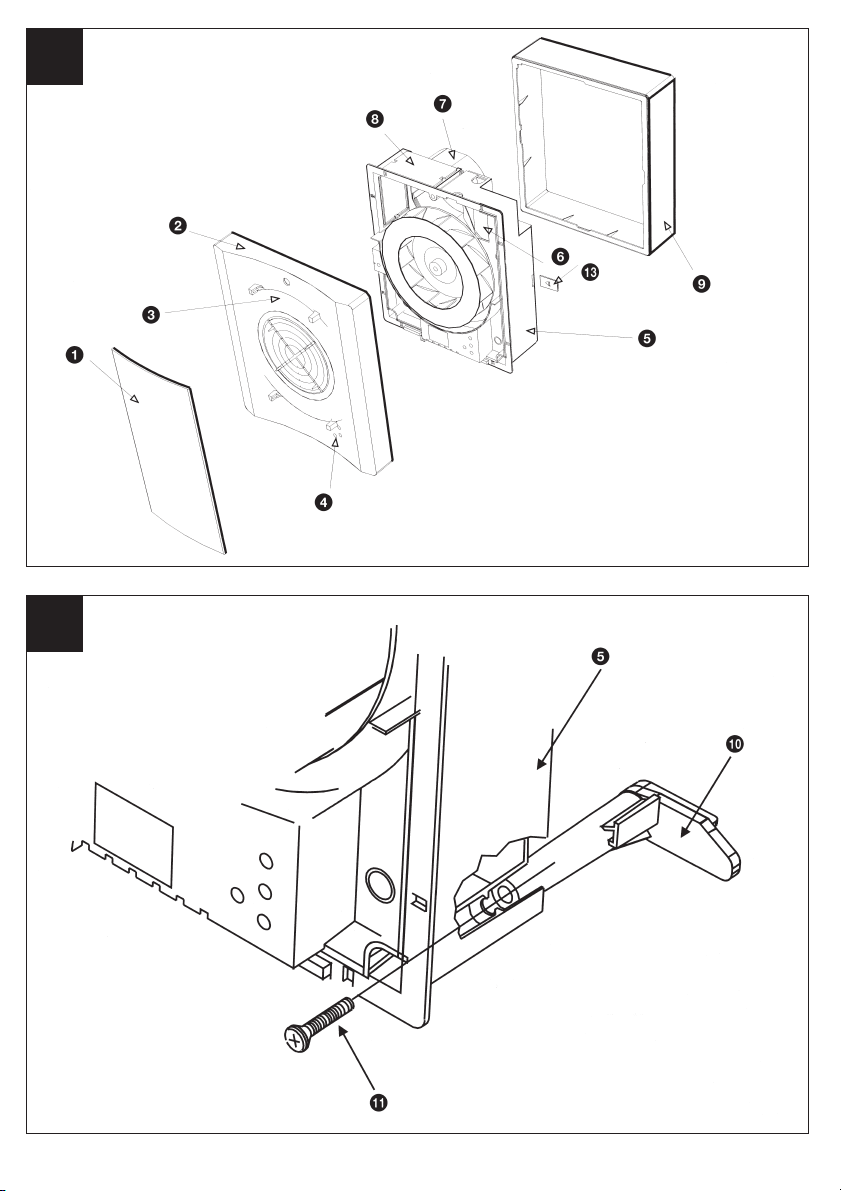
1 The surround 9is not required for this
installation.
2 Insert the fan box 5into the hole and
mark four positions using the slots in the
flange B.
3 Remove fan box 5from ceiling and fit
the four ceiling clips (supplied) over the
edge of the hole, so that the clips align
with the marks on the ceiling B.
4 Make a pilot hole 3.5mm diameter
through the hole of each clip. Ensure not
to damage the clip.
5 Fit the ducting to the circular spigot 7.
6 Offer the fan box 5up to the ceiling.
7 Pass the electrical cable into the fan box
5through the front cable inlet hole.
8 Using the screws !™, fix the fan box
flange to the ceiling clips.
1 Make good the outer hole if required.
Allow the mortar to set before continuing
the fan installation.
2 Fit the outer grille to the outer wall or for
ceiling mounting the appropriate
terminations.
♦If installing with a controller please refer
to Controller's Installation instructions.
♦Make sure the mains supply is isolated.
♦Before making electrical connections
pierce grommet with No. 2 pozi-drive
screwdriver.
DO NOT REMOVE GROMMET.
1 Remove the retaining screw of the
terminal cover 6and let the cover swing
out.
2 If wiring via cable clamp, remove the
cable clamp.
3a Wire the fan as shown in C. Check fan
model to diagram.
3b For dual speed operation, you will need a
COS (Change Over Speed Switch),
available from Xpelair.
3c For single speed operation at high speed,
connect the live supply to the LH
terminal.
3d For single speed operation at low speed,
connect the live supply to the LL
terminal.
4 If wiring via cable clamp, replace the
cable clamp and two screws. Ensure the
cable is firmly retained by the clamp.
5 Replace the terminal cover 6and fasten
the retaining screw.
6 Switch off the mains electrical supply
and remove fuses.
2 Mark on the wall or ceiling the positions
of the three fixing holes Din the fan box
5.
3 If wall mounting, drill three holes 5.5mm
diameter for wall plugs (supplied). If
ceiling mounting, use appropriate
fasteners.
4 Snap the surround support plates !£ to
the fan box 5.
5 Cut out the cable inlet hole in the
surround 9, if required. Slide the
surround 9over the fan box 5.
6 Pass the electrical cables into the fan box
5through the rear cable inlet hole.
7 Offer the fan box 5up to the wall or
ceiling making sure the circular spigot 7
enters the ducting.
8 Fix the fan box 5to the wall using
screws !¡ or to the ceiling using
appropriate fasteners (not supplied).
The surround 9is not required for this
installation. Fit the ducting to the circular
spigot 7.
If the hole size is as recommended:
1 Assemble the three fan body clamps !º
to the fan box 5using screws !¡.
2 Pass the electrical cables into the fan box
5through the front cable inlet hole.
3 Offer the fan box 5up to the wall
making sure the ducting enters the outer
wall. Ensure that the ducting slopes down
away from the fan to allow drainage of
any incoming water to the outside.
4 Tighten up the three screws !¡ until the
fan is clamped to the inner wall. The fan
body clamps !º will rotate to an
automatic stop position. Do not
overtighten.
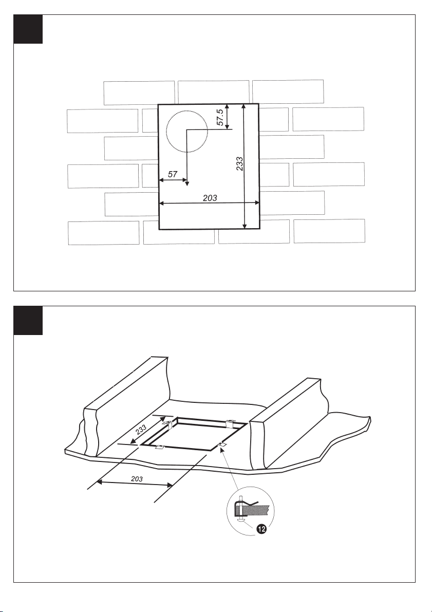
If the hole size is larger than
recommended i.e. larger than the flange
on the fan box 5.
1 The fan body clamps are not suitable.
2 Construct a wooden frame of internal
dimensions 203 x 233mm. Depth should
be at least 50mm.
3 Fit the wooden frame in the internal wall
and make good the hole.
4 Offer the fan box 5up to the wall
making sure the ducting enters the outer
wall. Ensure that the ducting slopes down
away from the fan to allow drainage of
any incoming water to the outside.
5 Allow the mortar to set before continuing
the fan installation.
6 Screw the fan box 5to the wooden
frame using the slots in the flange
(screws not supplied).
8
If installing in a wall
(flush mounting) Terminating the ducting
Wire the electrical connections
7 Connect the cable from the isolating
switch to the electrical supply wiring.
♦For fixed wiring circuits the protective
fuse for the appliance must not exceed
5A.
1 Refit front cover 2by placing the lower
lugs into the apertures on the fan box
flange and pivoting upwards over the
fan box 5. Fix with screw.
2 Fit spindle plugs 4onto the front cover
2.
3 Fit baffle plate 1onto the front cover 2
by locating the clips and carefully
snapping into position.
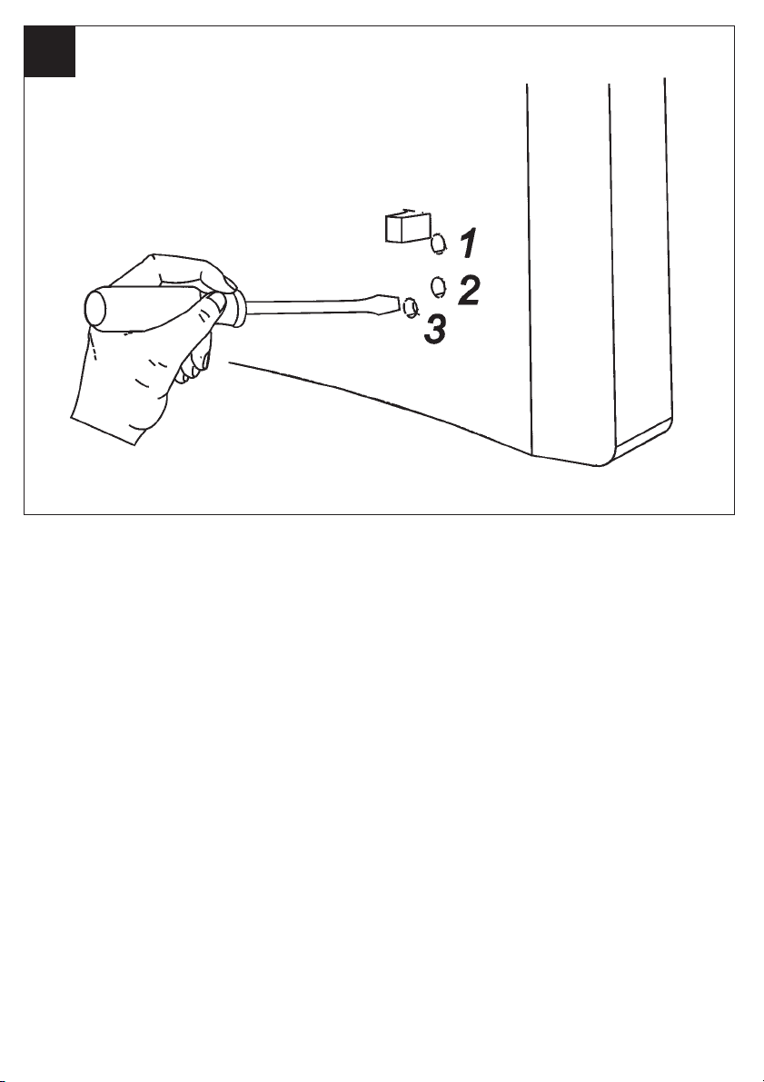
1 Before making any adjustments, isolate
the fan completely from the mains
supply.
2 Remove the baffle plate 1by unclipping
it using a sideways action.
3 Lever out the spindle plugs 4with an
electricians screwdriver.
4 Using an electrician's screwdriver, turn
clockwise to increase setting or anti-
clockwise to decrease setting.
DX200T
Timer over-run is approximately 2 minutes
minimum to 20 minutes maximum. Use
position 1G.
♦For single speed operation, the fan will
operate at the speed selected during
installation.
♦For dual speed operation, the fan will
operate at the speed selected on the COS
switch.
♦Operate the fan using the isolating
switch. Repeat to switch off.
(Light indicates when fan is switched on).
♦For single speed operation, the fan will
operate at the speed selected during
installation.
♦For dual speed operation, the fan will
operate at the speed selected on the COS
switch.
♦Operate the fan using the on/off switch.
When the switch is turned off, the fan
continues to operate for the adjustable
timer over-run period. (Light indicates
when fan is operating in manual mode).
Re-fitting fan covers
User adjustments
Using the fan
DX200
DX200T
If installing in a ceiling
(flush mounting)

For Eand F
1Baffle Plate
2Front Cover
3Rating Plate
4Spindle Plugs
5Fan Box
6Terminal Cover
7Circular Spigot
8Rectangular Blanking Plate - 2 off
9Surround
!ºFan Body Clamps - 3 off
!¡Clamps Screws and Wall Plug Screws
40mm long - 3 off
!™Ceiling Screws 25mm long - 4 off
!£Surround Support Plates - 3 off
♦Baffle plate 1must always be fitted
when the fan is operational.
♦Blanking plates 8must not be removed
unless directed to do so when the flat
ducting adaptor is fitted.
Before making electrical connections
pierce grommet with No. 2 pozi-drive
screwdriver.
DO NOT REMOVE GROMMET.
A QUALIFIED ELECTRICIAN MUST CARRY
OUT ALL CLEANING.
♦Before cleaning, isolate the fan
completely from the mains electricity
supply. Allow 3 minutes for the impeller
to stop rotating.
1 Remove the baffle plate 1by unclipping
it using a sideways action.
2 Clean the baffle plate 1by immersing in
warm soapy water. Dry thoroughly.
3 The front cover 2and surround 9
should be wiped clean with a damp cloth.
4 Refit the baffle plate 1onto the front
cover 2by locating the clips and
carefully snapping into position. Do not
immerse the fan in water or any other
liquids. The bearings are lubricated and
sealed during manufacture and require no
further attention. Regular cleaning of
your product is recommended.
♦Never use strong solvents to clean the
fan.
♦Apart from cleaning, no other
maintenance is required.
♦Do not immerse the fan in water or
other liquids to clean any other parts of
the fan.
9
Terminating the ductingElectrical safety components
Maintenance

Do’s
◆Do - Read all the instructions before commencing installation.
◆Do - Install each fan with a double pole isolation switch.
◆Do- Make sure that the mains supply is switched off before attempting to make electrical
connections or carry out maintenance or cleaning.
Guarantee
Customers outside UK - see International below.
◆UK: The fan is guaranteed against defects for 3 years from the date of purchase.
◆Xpelair reserve the right to repair or replace at their option.
◆Please keep your purchase receipt.
◆If you have any problems, contact Xpelair’s Head Office at the address shown below.
Technical advice and service
Customers outside UK - see International below.
UK: Xpelair have a comprehensive range of services including:
◆Free technical advice help-desk from Engineers on all aspects of ventilation.
◆Free design service, quotations and site surveys.
◆Service and maintenance contracts to suit all requirements.
Please ask for details:
◆By telephone on Techline: +44 (0)8709 000430
◆By fax on Techfax: +44 (0)8709 000530
◆At the address below.
Head Office, UK Sales Office and Spares
GDA Applied Energy Ltd, Morley Way, Peterborough PE2 9JJ England.
Telephone: +44 (0)1733 456789
Fax: +44 (0)1733 310606
Sales/Spares Hotline: +44 (0)8709 000420
Sales/Spares Faxline: +44 (0)8709 000520
http://www.xpelair.co.uk
International
◆Guarantee: Contact your local distributor or Xpelair direct for details.
◆Technical Advice and Service: Contact your local Xpelair distributor.
BS EN ISO
9001
FM11408
QAS 3284/37
18491AA
This manual suits for next models
1
Table of contents
Other Xpelair Premier Fan manuals
Popular Fan manuals by other brands

Fanimation
Fanimation TORCH FP8458 Series manual

Craftmade
Craftmade TMP52BNK5 installation guide

Brilum
Brilum CALLER 40 Installation and operating manual

The Modern Fan Company
The Modern Fan Company Arbor Flush DC Installation instructions and owner's manual

Vent-Axia
Vent-Axia Centrif 179 Installation and operation instructions

Zoo Fans
Zoo Fans H60-EC installation guide