XTE Electronic AMA 3008 User manual

UK_AutoMixers_V2.doc Rev 2.0 1
PUBBLIC ADDRESS SERIES
PROFESSIONAL AUTOMATIC MIXER
AMA 3150 AMA 3250
AM 3000 AM 3008
Owner’s Manual

UK_AutoMixers_V2.doc Rev 2.0 2
PUBBLIC ADDRESS SERIES
PROFESSIONAL AUTOMATIC MIXERS
AMA 3150 – AMA 3250 – AM 3000 – AM 3008
PRODUCT DESCRIPTION
Automatic mixer considerably improves the audio quality in all that applications of voice survey in
which more microphones are used. Softening microphones when they are not in use, an automatic
mixer helps to minimize background noise and reverberation, supplying a clearer and more
intelligible audio.
The mixer only starts relevant microphones in just 4 thousandths of a second.
Moreover, there is no need of specific microphones: mixer works with any kind of microphone or
professional radio microphone. XLR connectors make microphone connection quick and simple.
The starting threshold is automatically.
These features guarantee that the undesired background noise would be at minimum and that the
speaker voice instantly starts one microphone only.
When more than 8 microphones are necessary the Automatic Mixer Expansion AM 3008 is used.
It is connected to amplified mixer and mixer’s connector (LINK IN) by the special cable supplied
with the equipment (Patch cord CAT 5 FTP 8 pin whit TJ45).
The Expansion has 8 electronically balanced micro phonics inputs.
With the possibility to connect up to 2 expansions in cascade, could have a max of 24 micro
phonics inputs available.
This unit is therefore the extension of AMA 3150, AMA 3250 and AM 3000 units of which it
maintains the main features, advanced functions and possibility of internal modifies. (see under
Main Features and Installation)
MAIN FEATURES
AMA 3150, AMA 3250, AM 3000 and AM 3008 is equipped with a whole of features, which help, in
adapting mixer to particular applications.
• 8 electronically balanced microphone/line inputs (internal setting) characterized by:
a. 3 band adjustable equalizer for each micro phonic channel
b. Led for channel activation indication
c. Led for channel overload indication
d. Channel Gain control
e. Arrangement to insert transformer balance (optional)
f. 48 V phantom supply for each micro phonic channel
g. High-pass filter which could be excluded
• 2 selectionable CD/TAPE inputs with volume control, treble and bass tunes
• 10-band main equalizer on microphone, which could be excluded
• Main level indicator
• Main Master volume
• Input/output for external effect (antilarsen, etc.)
• Radio frequency-immune components and chassis.
• The whole electronic circulation has quality and safety features in working; it has an “earth-lift”
switch (on the back).

UK_AutoMixers_V2.doc Rev 2.0 3
• INTERNAL MODIFIES for particular functions:
a. Locked priority assignation to one or more microphones.
b. Exclusion possibility of MUTE and priority functions, for each input independently.
c. TAPE output whit direct inputs signal or post master selection.
• ADVANCED FUNCTIONS for flexible applications:
a. PRE OUT output (internal setting) could supplies the signal pre/post MASTER control and
pre/post equalizer.
b. Audio power outputs for loudspeakers are arranged for connection to constant voltage lines
50V, 70V, 100V and/or to constant impedance lines 4ohm.
c. Selection of 4 output lines of loudspeakers
d. Input (LINK IN) to connect up to 2 microphones expansions. TOTAL EXTENTION
CAPABILITY UP TO 24 MICROPHONES WITH AM3008 EXPANSION.
e. Output (LINK OUT) to connect AM 3008 Expansion to AMA 3150, AMA 3250 and AM 3000
(AM 3008 only)
• OPTIONAL ADVANCED FUNCTIONS
a. C 656 OPTIONAL REMOTE CONTROL CARD
Optional cards for independent volume remote control for each channel and for the master.
This card could have ON/OFF or volume function.
b. C 718 OPTIONAL CARD FOR LOGICAL FUNCTIONS
Optional card whit remote control connector for the logic circuits of each channel.
Optional card for logic functions selectionable by dip-switch on the back panel
I. FILIBUSTER: the first active microphone closes all the others
II. OVERRIDE: opens all the microphones
III. NOM: set On or OFF the NOM circuit
IV. LAST ON: the last active microphone remain open
FLEXIBLE FOR ANY APPLICATION
The Automatic Mixer could have various uses for sound enhancement, recordings and broadcast.
In each multi-micro phonic application, in which single speaker’s voice must be superior to
environmental noise and reverberation, AMA3150 supplies a clearer and more intelligible audio.
POSSIBLE USES
• Conferences
• Places of worship
• Hotels sound enhancement
• Court halls
• Audio conferences
• Hotels
• Schools
• Airports
• Offices
• Supermarkets
• Restaurants
• Motorway restaurants
• Auditorium
• Industries
• Gyms

UK_AutoMixers_V2.doc Rev 2.0 4
WHY AUTOMATIC MIXING IS NECESSARY
Installations with more microphones have always given several problems to audio technicians.
Using few microphones, some speakers have a clear audio, while others seem to be “far away”. If
too much microphones are used, the background noise is higher and it makes difficult listening to
the speakers.
A single speaker’s voice often reaches and is shot by more microphones and that causes a poor
audio quality. Since it is difficult choosing an exact no. of microphones to cover an area without
superimpositions, somebody should open and close microphones according to who is speaking.
This requires not only a great ability, but also a stressful quantity of work.
Use an automatic mixer.
HOW DOES AN AUTOMATIC MIXER WORK
Automatic mixing “opens” microphones when they are in use and it “softens” them when they are
not used.
Minimizing the number of simultaneously working microphones, that reduces the whole
background noise supplying a clearer and more intelligible audio.
Note: microphones opening, instead of turning on and off, gives a softer and more natural starting.
Softened microphones, even technically working, are quite “low” to seem closed.
APPLICATIONS WITH PA SYSTEMS
This kind of applications requires more than the others the automatic mixing. The ground is the
feedback, the high-frequency sound, which occasionally is heard from loudspeakers; each open
microphone increases feedback possibility. More microphones are open at the same time, more it
is likely that feedback happens; automatic mixers reduce this problem by keeping a minimum no.
of open microphones.
This unit includes a circuit (NOM) reducing of 3 dB the total gain of the system, any time the open
microphone no. doubles (i.e. from 1 to 2, from 2 to 4 and from 4 to 8); this keeps PA system under
the level in which feedback could happen.
POWER SUPPLY
The unit is expected to work with 230 VCA – 50/60Hz distribution system.
In case of power dysfunction, check the outside protection fuses (230 V~21 of fig. 1)) and
eventually replace them with others of same calibration; if one of them burns out immediately, do
not go on and have check the unit by qualified personnel.
Take away plug from 230 VCA electric power socket always, before removing fuses and, in any
case, open the unit framing.

UK_AutoMixers_V2.doc Rev 2.0 5
INSTALLATION
Advanced functions
• Commutators (19 of fig. 1a) enable loudspeakers to be silenced and could activate 4 different
zones separately.
• LINK IN input (34 of Fig. 1) is used to increase the disponibility of number of the microphones
connecting an expansion by one cable (Patch cord CAT 5 FTP 8 pin whit RJ45)
• LINK OUT (37 of Fig.1c) is used to increase the disponibility of number of the microphones
connecting the expansion by one cable (Patch cord CAT 5 FTP 8 pin whit RJ45)
• On the back panel, each microphonic input is arranged for insertion of 48V phantom power
supply and of high-pass filter through dip-switch (25 of fig. 1).
• There are JUMPER on the Master module for internal setting of PRE OUT output pre/post
Master and pre/post the equalizer (JP16, JP17, JP18 of FIG.5).
• Micro/line selection whit internal setting by jumper on the input module, jumper on=micro,
jumper open=line (JP7 of FIG.5)
• INTERNAL MODIFIES
Any modify has to be made in an authorized assistance centre or in factory directly.
• On each microphonic channel is possible to active the mute function of priority on the
remaining microphones. Each MUTE selected channel has the priority on the other
microphonic channels, which are going to be closed even if a speaker is talking. Also is
possible to set a channel in order than it can't be silenced by the MUTE function of the
other priority micro.
• TAPE REC output supplies the direct signal of the inputs without the eventually settled
tone corrections, or the post master signal, that is whit all the corrections settled by the
tone and level controls.
• OPTIONAL CARDS
Their insertion has to be made in an authorized assistance centre or directly in factory
• On each channel and on master there is arrangement for volume remote control card
insertion (Internal setting FIG.5), that connection has to be made by shielded cable
connect to the connector (32 of fig.1), without section limitations for distances up to 150
mt.
In remote place is possible to use potentiometer volume control or a switch for the
ON/OFF function. For connector connections see Fig.2
• The logic functions card has 4 selectable programs by the dip-switch (33 Fig.1).
a. FILIBUSTER: gets on this function when any microphone get activated prevent the
other microphones from get active till the speaker do a pause so long than the
relative microphone get deactivated. So the speaker than speaks can not be
interrupted.
b. ALL OVERRIDE: gets on this function all inputs are get actived, therefore the
microphonic signals are amplified as a not automatic mixer
c. NOM: set ON or OFF the NOM circuit that reducing the gain according to number of
open micophone.
d. LAST ON: blocking of the last microphone that maintain it active till it is not replaced
by the activation of another microphone. This function guaranties then environmental
acoustics is always present. Without this function, a long waiting in the conversation
causes the deactivation of all microphones; with the result of loses audio signal
effect.

UK_AutoMixers_V2.doc Rev 2.0 6
• The remote control card of logic circuits consents to extend the adjustment options and
opportunity of installations. The logic circuits could be used for different applications,
from simple ‘cough’ push button to complex environment systems adjusted by
computer.
a. GATE: when the respective audio channel is get activated by audio signal at its
input, it turn at ‘low’ logic condition.
b. MUTE: forced deactivation of channel when a ‘low’ logic signal is applied.
c. OVERRIDE: forced activation of channel when a ‘low’ logic signal is applied. MUTE
is priority when MUTE and OVERRIDE functions are activated.
d. LOGIC GROUND: logic ground is different to the audio ground. Connect at this pin
all logic ground points, supply’s ground of outside logic circuit enclosed. For avoid
‘click’ in commutation condition, do not connect the logic ground to the audio ground
or chassis or rack ground. The logic circuits are directing by multiple connector
DB25 on back panel ( 32 of Fig.1). The pins connections are in the following table.
LOGIC CIRCUITS CONNECTIONS (32 of Fig.1)
LOGIC FUNCTION INPUT CHANNEL CONNECTOR PIN NUMBER
GATE 1
GATE 2
GATE 3
GATE 4
GATE 5
GATE 6
GATE 7
GATE 8
1
2
3
4
5
6
7
8
1
15
4
18
7
21
10
24
OVERRIDE 1
OVERRIDE 2
OVERRIDE 3
OVERRIDE 4
OVERRIDE 5
OVERRIDE 6
OVERRIDE 7
OVERRIDE 8
1
2
3
4
5
6
7
8
14
3
17
6
20
9
23
12
MUTE 1
MUTE 2
MUTE 3
MUTE 4
MUTE 5
MUTE 6
MUTE 7
MUTE 8
1
2
3
4
5
6
7
8
2
16
5
19
8
22
11
25
Logic Ground all 13

UK_AutoMixers_V2.doc Rev 2.0 7
For a good system working
• Keep channel and master volume at about 80%.
• Adjust the GAIN (1 of Fig. 1) to have, in normal working conditions, maximum output power
(out meter = 0dB 16 of FIG.1a e 1b).
• Optimise intelligibility with channel and main equalizer.
• Reduce MASTER volume (15 of Fig. 1a e 1b) in order to obtain the required power.
• Be sure that mass commutator (29 of Fig. 1) is in mass-connected position.
LOUDSPEAKER CONNECTIONS (AMA 3150 and AMA 3250 only)
The device is provided with an output terminal board (35 of Fig.1a) where there are all impedances
available, for connection to constant impedance and constant voltage lines.
Moreover is provided with another multi-way output terminal board (36 of Fig.1a) with the chance
of subdivide total power on independent 4 zone selected by push buttons (19 of Fig.1a).
So could select to the outside the better loudspeakers type for the system to realize.
In Fig.3 there are any loudspeakers connections system example.
Constant voltage lines (50V, 70V, 100V)
In order to achieve the maximum efficiency of the system and to take precautions from amplifier
bad working, it is necessary to check the effective total power handling of the loudspeakers that
has to be equal or lower than the RMS power value of used amplifier. It’s a good rule arranging a
10-20% safety margin on the amplifier power capability. (equal bigger power)
Constant impedance lines (4ohm)
In order to achieve the maximum efficiency of the system and to take precautions from amplifier
bad working, it is necessary to check the effective loading impedance of the lines. The total
speakers impedance should be equal or higher than pre-selected value for connection.
To get that, each loudspeaker should be without transformer and should be connected in series or
in series-parallel groups; In any case loudspeakers should also have the same power handling.

UK_AutoMixers_V2.doc Rev 2.0 8
SPECIFICATIONS (AMA 3150-AMA 3250-AM 3000-AM 3008)
LINE Electronic balanced/Transformer optional
Maximum level: 100mV(GAIN max) 3V(GAIN min)
Input sensitivity: 8mV (-40dBu)/430mV (-5dBu)
MICRO Electronic balanced/Transformer optional
Maximum level: 2.5mV(GAIN max) 200mV(GAIN min)
Input sensitivity: 0,7mV (-61dBu)/45mV (-25dBu) ±1dB
CMRR: >60dB
Gain excursion 36dB
Hi-pass filter: 100Hz 6dB/oct
Phantom power supply: +48V
Impedance TAPE/CD: 47Kohm
Input sensitivity TAPE -12dBu
Input sensitivity CD -7dBu
Output impedance PRE OUT Electronic balanced/Unbalanced
140ohm bal ; 70ohm unbal
Output sensitivity: 0dBu
Output impedance REC Unbalanced 70ohm unbal
Output sensitivity: 0dBu
Output impedance SEND Unbalanced 70ohm unbal
Output sensitivity: 0dBu
Impedance RETURN 47Kohm
Input sensitivity: 0dBu
Bass: ±12dB a 70Hz
Mid: ±12dB a 700Hz
Treble: ±12dB a 10KHz
Equalizer: ±10dB Freq. 315, 500, 700, 1K, 1K4, 2K, 2K4, 3K15,
4K, 6K3Hz
Frequency response (-3dB) input CD: 50Hz÷20KHz
Frequency response (-3dB) input MIC: 100Hz÷16KHz
S/N RATIO 20÷20KHz weighted master at anticlockwise 95 dB
S/N RATIO 20÷20KHz weighted at clockwise 84 dB
EIN Micro (noise equal to the input) 20÷20KHz weighted
Rs=150ohm -126dBV
Power supply: 230V~ 50÷60Hz

UK_AutoMixers_V2.doc Rev 2.0 9
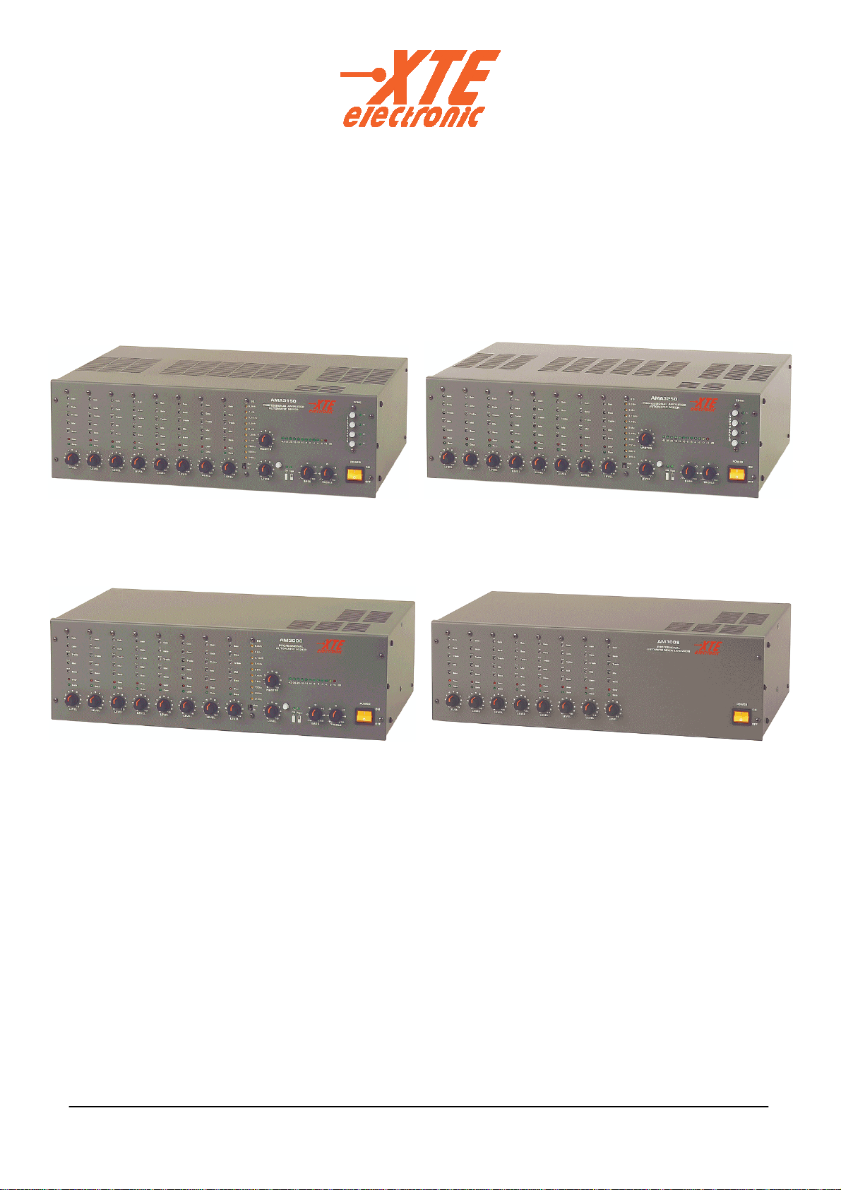
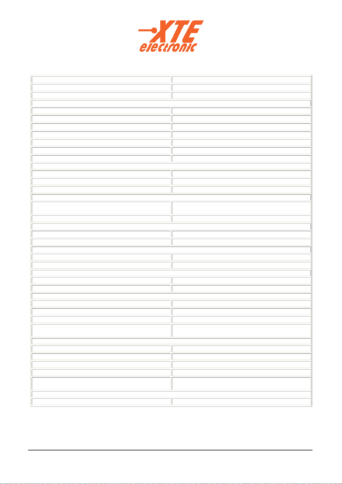
SPECIFICATIONS ( AMA 3150-AMA 3250-AM 3000-AM 3008)
AMA 3150 AMA 3250 AM 3000 AM 3008
Output power RMS 150W
50V, 70V, 100V 250w
50V, 70V, 100V
--------------------------
---------------------------
Output power IHF 225W
50V, 70V, 100V 375W
50V, 70V, 100V
--------------------------
---------------------------
Consumption: 200VA 300VA 20VA 20VA
Dimensions (WxHxD): 436 (Rack482)x132x304 436 (Rack482)x132x254
Weight (Kg): 12 14 2,5 2,5
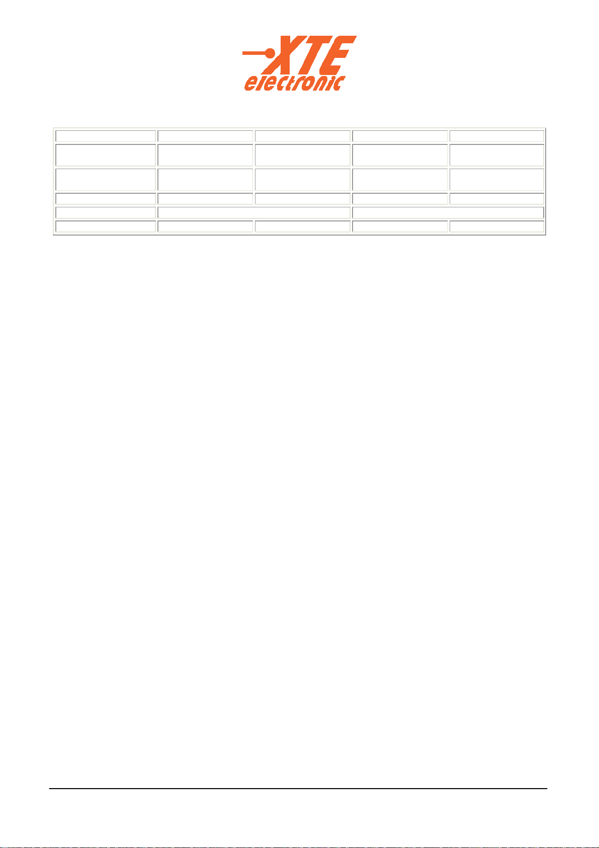
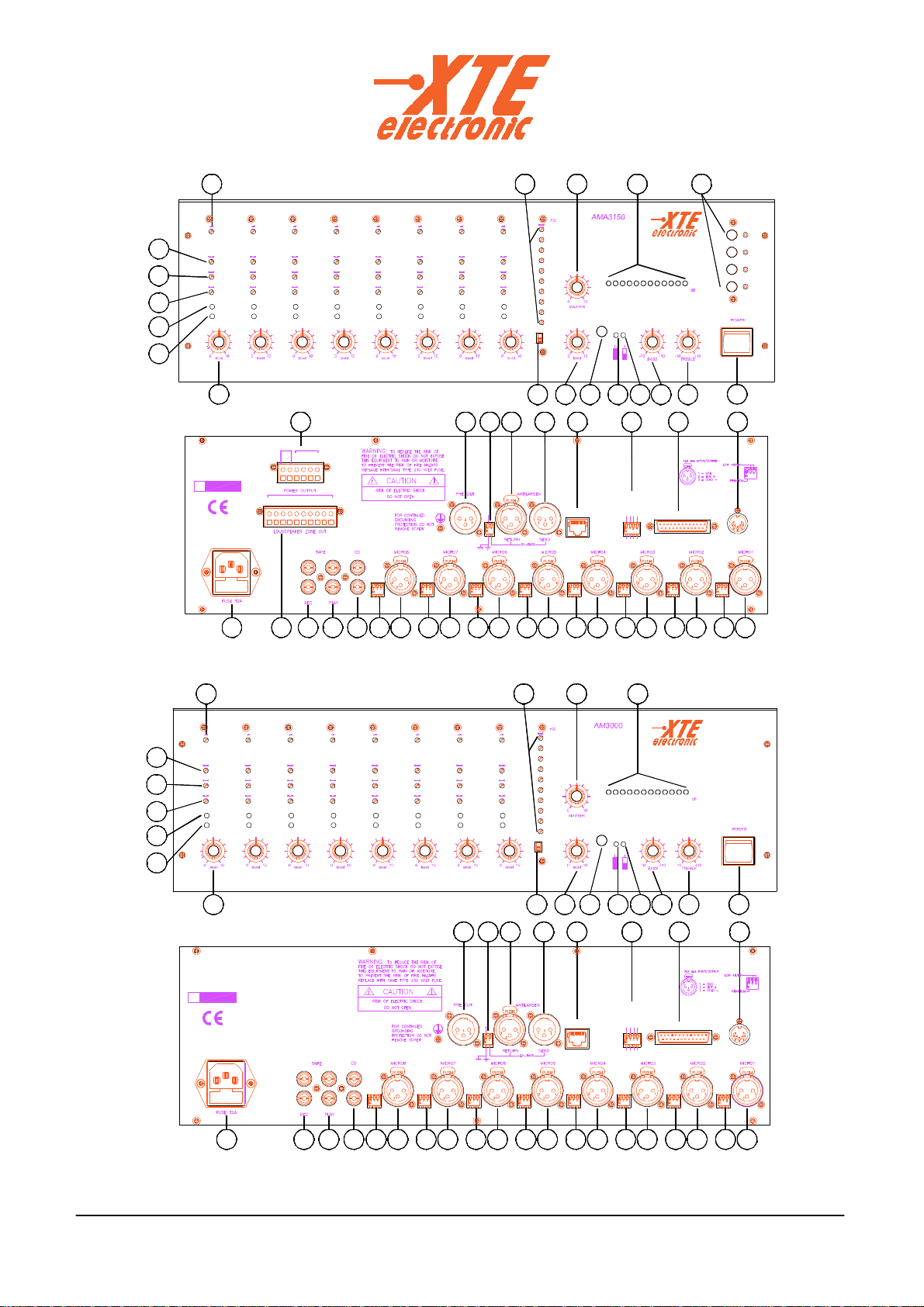
CONTROLS AND FUNCTIONS (as per Fig.1a, 1b e 1c)
1. GAIN – gain adjustment.
2. NC
3. TREBLE – treble adjustment.
4. MID – mid adjustment.
5. BASS - bass adjustment.
6. OVER – Led for channel overload indication
7. GATE - led indication of open channel.
8. LEVEL – MIC/LINE input volume.
9. BASS – CD/TAPE channel bass adjustment.
10. TREBLE - CD/TAPE channel treble adjustment.
11. TAPE – led indication of input TAPE selection.
12. CD – led indication of input CD selection.
13. CD/TAPE switch selector
14. LEVEL – CD/TAPE channel input volume.
15. MASTER – main volume.
16. VU meter – audio output level indicator.
17. IN/OUT – equalizer selector.
18. EQUALIZER – microphone main equalizer.
19. LOUDSPEAKER – speaker lines selector.
20. POWER – ON/OFF switch.
21. MAINS - 230 V~ supply mains socket, with protection fuse of CA mains.
22. TAPE REC - stereo output for audio recorder.
23. TAPE PLAY - stereo input for audio recorder.
24. CD - compact disc input.
25. PHANTOM / LOW FILTER – Micro-switch to connect 48 VCC phantom supply to inputs and
insert low-cut filter.
26. MICRO 1÷8 – micro/line input
27. ANTILARSEN SEND - output for external sound processing unit.
28. ANTILARSEN RETURN – input from external sound processing unit.
29. GND LIFT / BY-PASS - Micro-switch to connect electrical mass to chassis, and to by-pass
SEND / RETURN connections for antilarsen.
30. PRE OUT – mixed output of “pre” sector of amplifier.
31. VCA REMOTE VOLUME (option) – remote volume control connector
32. REMOTE LOGIC (option)– remote logic circuit control connector
33. PROGRAMS LOGIC(option) – Micro-switch for logic function programs selector.
34. LINK IN – input to extend the number of microphonic input by the AM 3008.
35. POWER OUT – direct speaker lines output.
36. LOUDSPEAKER ZONE OUT – loudspeaker lines output with zone selection
37. LINK OUT – output to connect AM 3008 to amplified mixer or mixer.

UK_AutoMixers_V2.doc Rev 2.0 10
FIG. 1a (Amplified Automatic Mixers AMA 3150-AMA 3250)
30
Over OverOver Over Over Over
5Gate
21
2 30V~ 50÷60Hz
7
6
S.N.
8
Gate
242236 23 25 26 25 26
1
4
70V
50V
COM
+
4
-+3
-+
2
- -
+
-
Ω
35
100V
IN
+-+
Gate Gate Gate Gate
Bass
Treble
Gain
3
4Mid
Bass
Treble
Mid
Gain
1
Mid
Bass
Treble
Gain
Mid
Bass
Treble
Gain
Bass
Treble
Mid
Gain
Treble
Mid
Bass
Gain
Over Over
LINK IN
NO M ON
LA ST ON
A LL O'RIDE
FILIB
GN D LIFT
25 26 25 26 25 26 25 26
NOM OFF
AUTO
AUTO
AUTO
14
2829 27
GateGate
17
In
Out
500Hz
315Hz
34
LOGIC
PROGRAMS
33
13 12 11
TapeCD
REMOTE LOGIC
25 26 25 26
32
REMOTE VOLUME
VCA
31
109 20
OFF
ON
-6
3,15kHz
Bass
Treble
Mid
Gain
Mid
Bass
Treble
Gain
1 kHz
1,4kHz
700Hz
2,4kHz
2 kHz
6,3kHz
4 kHz
18
PROFESSIONAL AMPLIFIED
AUTOMATIC MIXER
-43 -26-35 -16 -10-14 -8
15 16
-2-4 0 +4
L
O
U
D
S
P
E
A
K
E
R
2
4
3
1
ZONE
19
Fig.1b (Automatic Mixer AM3000)
21
230V~ 50÷60Hz
5
S.N.
6
7
8
Gate Gate
3
4
Bass
Over
Treble
Mid
Bass
Over
Treble
Mid
Gain Gain
1
252422 23 2625 2526 26 2625 25 262526 26
AUTO
AUTO
AUTO
NOM OFF
25 26 25
AUTOMATIC MIXER
13
PROFESSIONAL
GateGate Gate Gate
30 2829 27 34
GND LIFT
LINK IN
GateGate
17 14
500Hz
315Hz
Out
In
Bass
Treble
OverOver
Bass
Mid
Treble
Over
Bass
Mid
Treble
Gain Gain
Over
Bass
Mid
Treble
Mid
Gain Gain
Bass
Treble
Mid
Over
Gain
Bass
Treble
Mid
Over
Gain
1 kHz
1,4kHz
2,4kHz
2 kHz
700Hz
4 kHz
3,15kHz
6,3kHz
18 15
20
REMOTE VOLUME
3133 32
FILIB
PROGRAMS
LOGIC
A LL O'RIDE
LA ST ON
NO M ON
REMOTE LOGIC
VCA
12 911
TapeCD
10
OFF
ON
-16-43 -35 -26 -14 -10 -6-8 -4 +40-2
16

UK_AutoMixers_V2.doc Rev 2.0 11
Fig.1c (Expansion AM 3008)
21
6
230V~ 50÷60Hz
S.N.
8
7
Bass
Treble
Mid
Gate
Over
Gain
5
4
3Treble
Bass
Over
Gate
Mid
Gain
1
26262422 23 25 26 25 25 26 25 26 25 262525 26 26 25
PROFESSIONAL
AUTOMATIC MIXER EXPANSION
GND LIFT
LINK IN
29 34
Treble Treble
Bass
Over
Gate
Mid
Bass
Gate
Over
Mid
Gain Gain
Treble Treble
Bass
Gate
Over
Mid
Bass
Over
Gate
Mid
Gain Gain
TrebleTreble
Bass
Over
Gate
Mid
Bass
Over
Gate
Mid
Gain Gain
20
REMOTE VOLUME
31
REMOTE LOGIC
ALL O'RIDEAUTO
AUTO
LINK OUT
FILIB
NOM OFF
AUTO LAST ON
NOM ON
PROGRAMS
LOGIC VCA
3337 32
OFF
ON
FIG.2
C10K
MAX
MIN
X = 1÷8 MICRO CHANNELS; MASTER VOLUME; TAPE & CD
2 = GROUND
1 = OPTIONAL CONTROL X
3 = OPTIONAL CONTROL X
4 = OPTIONAL CONTROL X
5 = OPTIONAL CONTROL X
ON
OFF
SHIELD
REMOTE CONTROL
VCA

UK_AutoMixers_V2.doc Rev 2.0 12
Fig.3c _ Constant impedance and voltage lines connection example for AMA3250
30W
100V
35W
100V
Fig.3b _ Constant voltage lines connection
30W
100V
100V
30W
LOUDSPEAKER ZONE
IN 21 3 4
4Ω
Z tot= 8Ω
4Ω
125W
50
100
70
COM
Ω
4
V
0
Fig.3 _ LOUDSPEAKER LINES CONNECTION FOR AMA3150 AND AMA3250
Fig.3a _ Constant impedance lines connection
Z tot= 4Ω
50
100
70 V
COM
50V50V 50V
Ω
4
0
100
Ω
50
70
COM
4
V
0
4Ω 4Ω
100
COM
100V 100V
50
70 V
0
4Ω
4Ω 4Ω
100V
FIG. 4
LOW FILTER
-
LOUDSPEAKER ZONE OUT POWER OUTPUT
PROGRAMS
LOGIC
+
POWER OUTPUT
34 +-+-2-1+IN
-+
AUTO
50V
4Ω
-
+
COM
100V
70V
NOM OFF
AUTO
AUTO
PHANTOM
FILIB
ALL O'RIDE
LAST ON
NOM ON

UK_AutoMixers_V2.doc Rev 2.0 13
FIG. 5
JP7 JP4
JP14
MICRO / LINE
TAPE / CD
MASTER
JP16
JP17
JP18
JP7 On = micro sensibility.
Open = line sensibility.
JP4 On = without volume remote control board
(option).
Open = with volume remote board in (option).
JP1 On = without volume remote control board
(option).
Open = with volume remote board in
(option).
Don't get on more than one jumper for time.
JP17 On = POST master PRE OUT output signal.
JP18 On = PRE equalizer PRE OUT output signal.
JP16 On = POST equalizer and PRE master
PRE OUT output signal.
BUS
JP14 On = without volume remote control board
(option).
Open = with volume remote board in (option).

UK_AutoMixers_V2.doc Rev 2.0 14
!!
"#$%&#
' ($)))#
Table of contents
Other XTE Electronic Mixer manuals