XTE Electronic HP2150 User manual

User’s Manual 1 17
H
H
Hi
iig
g
gh
h
h
P
P
Pr
r
re
e
ec
c
ci
iis
s
si
iio
o
on
n
n
S
S
Se
e
er
r
ri
iie
e
es
s
s
H
H
HP
P
P2
2
21
1
15
5
50
0
0
–
–
–
H
H
HP
P
P2
2
22
2
24
4
40
0
0
D
D
Di
iig
g
gi
iit
t
ta
a
al
ll
A
A
Am
m
mp
p
pl
lli
iif
f
fi
iie
e
ed
d
d
M
M
Mi
iix
x
xe
e
er
r
r
U
U
Us
s
se
e
er
r
r’
’
’s
s
s
M
M
Ma
a
an
n
nu
u
ua
a
al
l
l

User’s Manual 2 17
Table of contents
1. Important safety instructions 3
2. Declaration of conformity 3
3. User’s liability 4
3.1 Damages to the loudspeakers 4
3.2 Dangerous output voltage 4
3.3 Radio interferences 4
4. Introduction 4
4.1 Unpacking 4
4.2 Assembly 4
5. Description 5
6. Features 5
7. Front Panel: Controls and Indicators 6
8. Back Panel: Controls and Connectors 6
9. Power Supply 7
10. Connections 7
10.1 General criteria 7
10.2 Balanced Mic / Line Input 7
10.3 Direc Out 7
10.4 Pre Out 1 / Pre Out 2 7
10.5 CD / AUX 7
10.6 REC 7
10.7 Remote / Priority 7
10.8 Power Output 8
11. Protection System 9
11.1 Power Output Short Circuit 9
11.2 Turn On / Turn Off Delay 9
11.3 Power Unit Over Temperature 9
11.4 Power Supply Over Voltage 9
11.5 Power Supply Soft Start 9
12. Advanced Functions 9
12.1 Noise Gate 9
12.2 Remote 9
12.3 Priority 10
13. Advanced Functions – DSP Section 11
13.1 Programmable settings („Presets“) 11
13.2 Changing between presets 11
13.3 Temporarily changing on existing preset 11
14. Extended Functions – DSP Section 12
14.1 Programming a new preset 12
14.2 Programming the Mixer 12
14.3 General comments on programming the DSP 13
14.4 Presets 13
14.5 Parameters 13
14.6 Config 14
14.7 Utility 14
14.8 Quick reference: DSP menu structure 15
15. System SetUp (Step by Step) 16
16. Configuration Example 16
17. Technical Specifications 17

User’s Manual 3 17
1. Important safety instructions
This symbol indicates
the presence of
important directions for
use and information
that should be given
particular attention so
as to use the product
properly.
This symbol indicates
the presence of
“dangerous voltage”
that may cause the risk
of electrical shock. Pay
the utmost attention
and proceed
cautiously.
1. Follow carefully the attached documentation
and keep it for future reference
2. Comply with the warnings
3. Store the packaging and check that all material
is in excellent conditions.
4. Do not use water near the product, do not pour
water or any other liquid on the amplifier. Do not
to use it with wet hands or feet into the water.
5. Do not use next to heat sources such as
radiators, stoves or the like.
6. Check the integrity of the mains cable. Do not
tread on the cable and do not squeeze the plug.
7. Connect the plug to a socket equipped with
grounding. Do not camper the plug. If the plug
supplied is not consistent with your socket, please
apply to an electrician for its replacement.
8. Connect to supply mains with the same voltage
as indicated on the back of the amplifier.
9. Install the amplifier in compliance with the
instructions.
10. Do not obstruct the air ducts.
11. Disconnect the appliance in case of storm and
if unused.
12. Connect according to the instructions only.
13. Do not connect input signal higher than that
indicated in the manual.
14. Do not connect the amplifier output to the
input of another channel.
15. Do not connect any output of the amplifier to
power sources such as battery, voltage supply or
outlet, regardless of the amplifier is on or off.
16. Keep the volume controls to a minimum during
the amplifier switching on/off .
17. Do not remove the upper or lower cover: there
is a risk of electrical shock.
18. Do not try to self-repair the appliance, but
apply to qualified personnel.
19. Clean with a dry cloth only.
20. The product shall be handled by skilled
personnel in the following cases:
•mains cable or plug damaged
•Exposure of the product to rain or humidity
•Some liquid entered inside the unit.
•An object fell on the unit
•The unit fell down and is damaged
•The product does not work correctly or shows
a remarkable change of performance.
21. A careful supervision is necessary if the
product is used in the presence of children or
inexpert adults.
22. This product could produce sound levels,
which cause damage to the hearing. Pay the
utmost attention and do not operate at high level
of volume or at an uncomfortable level for a long
time. Consult an audiometric specialist in case of
hearing loss or complaints.
2. Declaration of conformity
This device conforms to the requirements of the
EMC directive 89/336/EEC, amended by
92/31/EEC, and the requirements of the Low
Voltage Directive 73/23/EEC, amended by
93/68/EEC.
Standards Applied:
EN55103-1 (Emissions)
EN55103-2 (Immunity)
EN60065, Class I (Safety)

User’s Manual 4 17
3. User’s liability
3.1. Damages to the loudspeakers
Always check the peak and continuous power of
the loudspeakers.
This amplifier is extremely powerful and can be
potentially dangerous both for the loudspeakers
and for the persons.
Most loudspeakers may be easily damaged or
broken. Even if there is a gain reduction through
the attenuators on the amplifier’s front panel, it is
still possible to reach the maximum output power
if the input signal level is high enough.
3.2. Dangerous output voltage
The amplifier can generate hazardous output
voltage. Do not touch exposed cables of
loudspeakers with the amplifier in operation.
3.3 Radio interferences
A sample of this product has been tested and
approved to meet the requirements of the
Electromagnetic Compatibility Directive (EMC).
These requirements have been defined so as to
provide reasonable protection against dangerous
interference of electrical equipment. Whenever
this product has not been installed or handled
according to these guidelines, it might interfere
with other equipment such as radio receivers.
However, there is no guarantee that they should
not occur in a specific installation. Should this
equipment interfere with transceiver equipment
(such possibility can be checked by switching on
and off the device), the user should try to cancel
the interference by observing one or more of the
following measures:
•Increase the distance between the device and
the receiver.
•Connect the device to a plug linked to a
different circuit with respect to the one to
which the receiver is connected.
•Redirect or move the receiver’s antenna.
•Make sure that the unit concerned conforms
to the EMC immunity limits (CE-labelled). All
electrical equipment sold in the EC should be
approved as for what concerns protection
against electromagnetic fields, high tension
and radio interference.
•Contact qualified personnel.
4. Introduction
Congratulations on choosing XTE device and
thanks for trusting us and our products. Your
device has been carefully planned in the smallest
details, starting with every part of its equipment till
final assemblage. All products XTE are made with
the main purpose of guaranteeing our clients’ full
satisfaction, thus we underline that the product
you have choosen uses the most advanced
technology.
An improper use of the device can compromise its
correct operation. Therefore we recommend you
to carefully and correctly use it.
Read this manual carefully as it contains essential
information for a safe use of your device.
4.1. Unpacking
Immediately inspect the package and its content
so as to check whether there are any signs of
damage. After unpacking check the product and
all parts, if you notice any damage inform your
dealer immediately.
It is advisable to save the packaging materials
even if the amplifier shows no sign of shipping
damage; you might have to return it to XTE or to
one of its dealers. Use the original package only,
which is the best way to protect the equipment
from shipping mishandling.
4.2. Assembly
Metal framing of all the XTE products is suitable to
be supported on a surface (table, etc.) and is
equipped with separated stirrups for assembly in
19” rack standard.
482.6
340.15
Fig1. Dimension for mounting
Pay particular attention during the installation; we
remind you that the devices should not be
installed in places with:
•High temperatures
•Dust and excessive humidity
•Presence of intense magnetic fields
•Water next to the component
•Vibrations
•Closed spaces inhibiting a proper ventilation

User’s Manual 5 17
5. Description
HP2150 and HP2240 are bi-amplified sound
systems that combine the flexibility of 7 inputs
analog mixer with the high quality audio
processing of dual channel 96kHz sample rate
DSP and the high efficiency of class D switching
amplifiers.
This results in a new generation of compact
devices which allow a quick and easy solution for
whichever audio installations where clear and
intelligible audio broadcasting is an essential
requirement, such us places of worship, court
halls and auditoriums.
The DSP configuration is intuitive and easy
handling thanks the two rotary encoders and the
2x20 backlight LCD display that allow the
navigation of the Menu.
The device is equipped with its own graphic user
interface.
This makes programming simple and
straightforward – Laptop or PC are no longer
required.
Up to 20 different sets of settings, so-called
„presets“, can be programmed and can easily be
recalled by the user for each occasion as
required.
The maximum sound effect accuracy is
guaranteed from the analog noise gate and 3
band EQ for each input and also from the 31 Band
Graphic EQ and the 6 PEQ available in the DSP
processor parameters.
The two channel Class D integrated power unit
(2x150W and 2x240W) allows high power range
in compact size and low weight.
Both models operate on 230 VAC, 50Hz and may
be desk or rack mounted.
The High Precision Series is extremely versatile,
all in one solution, yet cost-effective, and is easy
to install and operate.
6. Features
Amplified Mixer Section:
•Constant Impedance and constant Voltage
outputs
•2 Amplified Outputs
•Switching power supply
•Class D output circuit topology
•Low weight high Efficiency
•Full protections
•Low mains current draw
•Output Limiter
•Input signal presence and Clip indicators
•Output Clip and Protect state indicators
•5 balanced Mic/Line XLR inputs selectable
•2 stereo Auxiliary RCA inputs
•1 Stereo REC RCA output
•3 band Equalizer for each channel
•Noise Gate function for each channel
•2 balanced XLR processed outputs
•1 balanced XLR Direct output
•Selectable 48Vdc Phantom Supply
•Advanced Prority System
•Arranged for 19” rack mounting in 2 unit
space
DSP Section:
•2 channels 24bit/96kHz DSP Processor
•20 memory Presets
•4 memory Parameterset
•31band Graphic EQ for each channel
•6 PEQ for each channel
•Delay (680ms/233mt Max)
•Preamplifier Limiter
•User or qualified personnel access levels
•2x20 backlight LCD Display
•Easy handling configuration
•Volume/Preset control protection
Optional Features
•C656-RJ Remote control optional card for the
control of the master volume level of each
channel
•C714 Din Don optional card with trimmer to
adjust the volume (internal adjustment)

User’s Manual 6 17
7. Front Panel: Controls and Indicators
I
0
GAIN
TREBLE
MIDDLE
BASS
GATE
LEVEL
0
1
2 8
9
10
3
456
7
CLIP
SIG
GAIN
TREBLE
MIDDLE
BASS
GATE
LEVEL
0
1
2 8
9
10
3
456
7
CLIP
SIG
GAIN
TREBLE
MIDDLE
BASS
GATE
LEVEL
0
1
2 8
9
10
3
456
7
CLIP
SIG
GAIN
TREBLE
MIDDLE
BASS
GATE
LEVEL
0
1
2 8
9
10
3
456
7
CLIP
SIG
GAIN
TREBLE
MIDDLE
BASS
GATE
LEVEL
0
1
2 8
9
10
3
456
7
CLIP
SIG
CD
AUX
LEVEL
0
1
2 8
9
10
3
456
7
BASS
-10
-8
-6 6
8
10
-4
-2 02
4
TREBLE
-10
-8
-6 6
8
10
-4
-2 02
4
POWER
DIGITAL
AMPLIFIED MIXER
CLIP
PROT
CLIP
PROT
VOLUME
PRESET
-50 -38 -30 -22 -15 -9 -3 0 dB
VALUE PARAMETER
VOLUME PRESET
PRESS
ENTER
PRESS
BACK
1
2
1
2
OUT STATE HP 2240
CH5CH4CH3CH2CH1
18171614111098
1 2
12 13
3 4
15
5 6 7
1. GATE – MIC/LINE input Noise Gate activation threshold control
2. GAIN – MIC/LINE input gain control
3. AUX / CD – AUX/CD input selector
4. TREBLE – AUX/CD inputs Treble tone control
5. CLIP – Output 1 and Output 2 signal Clip led indicator
6. PROT – Power unit 1 and Power unit 2 protect state led indicator
7. LCD – 20x2 Back light LCD display for DSP parameters view
8. TREBLE – MIC/LINE input Treble tone control
9. MIDDLE – MIC/LINE input Middle tone control
10. BASS – MIC/LINE input Bass tone control
11. LEVEL – MIC/LINE input level control
12. SIG – MIC/LINE input Signal presence led indicator
13. CLIP – MIC/LINE input signal Clip led indicator
14. LEVEL – AUX/CD inputs level control
15. BASS – AUX/CD inputs Bass level control
16. VOLUME / VALUE / BACK – Volume, Value and Back navigation control for DSP processor
17. PRESET / PARAMETER / ENTER – Preset, Parameter and Enter navigation control for DSP
18. POWER – Power on switch
8. Back Panel: Controls and Connectors
1
ON
2 3
1
3
2
PUSH
1
3
2
PUSH
1
3
2
PUSH
1
3
2
PUSH
1
3
2
PUSH
1
ON
2 3 1
ON
2 3 1
ON
2 3 1
ON
2 3
5 76 81 2 3 4
PRE OUT 2 PRE OUT 1 REMOTE
PRIORITY
REC CD AUX
BALANCED MIC / LINE INPUTS
CH 1CH 2CH 3CH 4CH 5
48V
PHANTOM
ON
LINE
48V
PHANTOM
ON
LINE
MIC
48V
PHANTOM
ON
LINE
48V
PHANTOM
ON
LINE
48V
PHANTOM
ON
LINE
DIRECT OUT +6dB
230V~ 50 ·60Hz
FUSE T A/250V~
MAINS
PROTECTION DO
NOT REMOVE SCREW
GROUNDING
FOR CONTINUED
100V
70V
50V
COM
-
W4
POWER OUTPUT
+
1
2
DO NOT OPEN
RISK OF ELECTRIC SHOCK
CAUTION
FIRE OR ELECTRIC SHOCK DO NOT EXPOSE
TO REDUCE THE RISK OF
THIS EQUIPMENT TO RAIN OR MOISTURE.
TO PREVENT THE RISK OF FIRE HAZARD
WARNING:
REPLACE WITH SAME TYPE 250 VOLT FUSE.
3 = COLD -
2 = HOT +
1 = GND
3
2 1
INPUT / OUTPUT
XLR BAL
S.N.
Made in Italy
MIC MIC MIC MIC
19 20 21 22
23 24 25 26 27 28 29 30 31 32
19. MAINS – AC 230V power supply socket, with incorporated protection fuse
20. POWER OUT – Output 2 connector for loudspeaker lines connection
21. MICROSWITCHS – MIC/LINE input sensitivity selector and 48V Phantom activation
22. MIC / LINE – Balanced inputs with variable sensitivity
23. POWER OUT – Output 1 connector for loudspeaker lines connection
24. PRE OUT 2 – Mixed and processed output of the DSP channel 2
25. PRE OUT 1 – Mixed and processed output of the DSP channel 1
26. REMOTE – RJ45 connector for remote Master level and Priority control
27. PRIORITY – Phoenix connector for configurable priority function control
28. REC – Mixed stereo line output
29. CD – Stereo CD input
30. AUX – Stereo line input
31. DIRECT OUT – Mixed output of the amplifier without DSP processing
32. LEVEL – Direct out level control

User’s Manual 7 17
9. Power Supply
The unit is expected to work with 230 VCA –
50/60 Hz distribution system.
In case of power dysfunction, check the outside
protection fuses and eventually replace them with
others of same calibration; if one of them burns
out immediately, do not go on and have check the
unit by qualified personnel.
Take away plug from 230 VCA electric power
socket always, before removing fuses and, in any
case, open the unit framing.
10. Connections
10.1. General criteria
In order to allow the equipment to work correctly,
it is advisable to comply with a number of general
criteria when making the connections:
•Avoid positioning cables or microphones on
the cabinet of the equipment.
•Avoid laying the signal lines parallel to the
power-supply lines. Keep a minimum distance
of 30/40 cm.
•Position the input lines and the output lines at
a distance from one another.
•In order to avoid acoustic feedback (the
Larsen effect), position the microphones out
of the angle of coverage of the loudspeakers.
10.2. Balanced Mic / Line Inputs
The 5 female XLR input sockets (22) for the mic /
line level signals are located on the rear panel of
the equipment. The figure Fig2. shows the
connections to these sockets. These inputs are
electronically balanced.
The mic / line sensitivity could be selected through
the multi-micro switch (21) placed on the left of
the socket.
48Vdc “phantom” supply could be joint to each
socket (on the same balanced phonic line),
through the multi-micro switch (21) placed on the
left of the socket; therefore, before connecting a
microphone it should pay attention to the model (if
dynamic or electret). In case of dynamic
microphone do not insert 48 VCC; insert it with
electret microphone only.
10.3. Direct Out
The male XLR direct output socket (31) for the
preamplified signal not DSP processed are
located on the rear panel of the equipment. The
figure Fig2. shows the connections to this socket.
This output is electronically balanced.
The output signal level could be adjusted through
the potentiometer (32) placed on the right of the
socket.
10.4. Pre Out 1 / Pre Out 2
The 2 male XLR output sockets (24-25) for the
preamplified signal DSP processed are located on
the rear panel of the equipment. The figure Fig2.
shows the connections to these sockets. These
outputs are electronically balanced.
3 = COLD -
2 = HOT +
1 = GND
3
2 1
Fig2. XLR Bal Input / Output Pin-out
10.5. CD / AUX
The 2 couple of mono female RCA input sockets
(29-30) for the CD and AUX sources are located
on the rear panel of the equipment. These inputs
are unbalanced.
These 2 inputs are alternatively selected by a
switch (3) located on the front panel.
When the CD input is selected by the switch
located on the front panel, the AUX input is
directly mixed with the other inputs for allows the
connection in cascade of an external mixer’s Pre
Out in the way to expand the system input
capability. This feature could be deactivate
following the indications described in the Fig6.
10.6. REC
The couple of mono female RCA output socket
(28) for the REC preamplified signal not DSP and
3 band EQ of each channel processed is located
on the rear panel of the equipment. This output is
unbalanced.
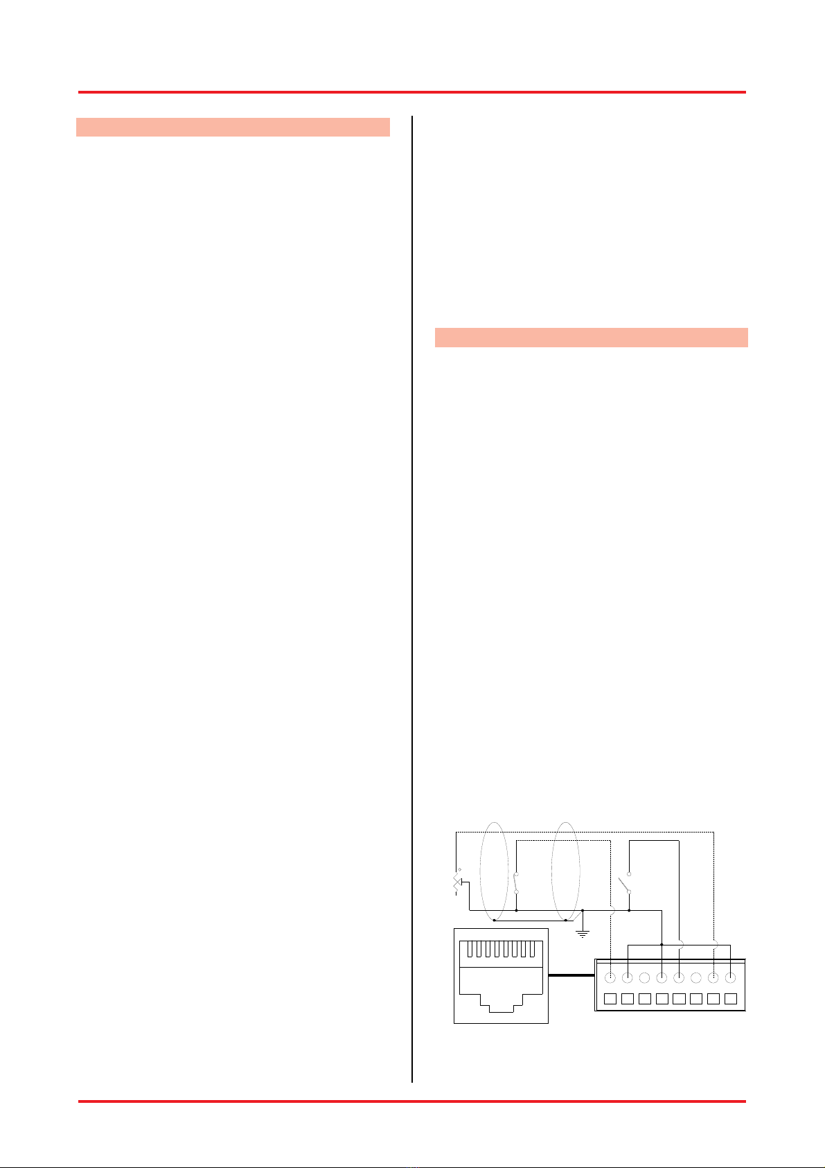
10.7. Remote / Priority
The female RJ45 socket (26) for the remote
control are located on the rear panel of the
equipment.
The Priority function is also available on the 2 pole
phoenix-type (27) connector located on the right
of the socket. The Priority function could active
the chime if C714 Din Don optional card is used.
The remote master volume level control for each
output channel is available if the C656-RJ Remote
control optional cards is used.
The remote control and priority functions are
deeply described in the chapter 12 advanced
functions.

User’s Manual 8 17
10.8. Power Output
The device is provided with a multi-way power
output terminal strip for constant-voltage
distribution (50, 70, 100 V) and low impedance (4
Ohms ) systems (20-23).
Constant voltage lines
50, 70, 100 V terminals should be used with each
loudspeaker equipped with impedance-matching
transformers and parallel connected. This fact
makes the system easy to create and, if any of the
loudspeakers should be disconnected from the
line for any reason, the rest of the system would
continue to function properly. The figure Fig3.
shows the connections of the line to these
sockets.
In order to achieve the maximum efficiency of the
system and to take precautions from amplifier bad
working, it is necessary to check the effective total
power handling of the loudspeakers that has to be
equal or lower than the RMS power value of used
amplifier. It’s a good rule arranging a 10-20%
safety margin on the amplifier power capability.
Constant impedance lines
4 Ohms terminal should be used.
In order to achieve the maximum efficiency of the
system and to take precautions from amplifier bad
working, it is necessary to check the effective
loading impedance of the lines. The total speakers
impedance should be equal or higher than pre-
selected value for connection.
To get that, each loudspeaker should be without
impedance-matching transformer and should be
connected in series or in series-parallel groups; In
any case loudspeakers should also have the
same power handling. The figure Fig4. shows the
connections of the line to these sockets.
70V
100V
70V
50V
COM
-
W4
POWER OUTPUT
+
100V
100V
70V
50V
COM
-
W4
POWER OUTPUT
+
70V 70V 100V 100V
Fig3. Constant Voltage Lines
100V
70V
50V
COM
-
W4
POWER OUTPUT
+
100V
70V
50V
COM
-
W4
POWER OUTPUT
+
8W
Z tot= 4WZ tot= 4W
8W
W4
W4
W4
W4
Fig4. Constant Impedance Lines

User’s Manual 9 17
11. Protection Systems
In addition to the usual protection consisting of
fuses, these products are complete of different
protection devices in order to safeguard them
from possible risks of damage. Protection
conditions are signalled by the fact that the PROT
(6) signalling lamp located on the front panel of
the equipment will light (Short Circuit excluded),
the unit will stop working and only the fan will
continue to run.
11.1. Power Output Short Circuit
Applying a lower loading impedance than the
rated value means requiring the equipment to
supply a power higher than it can do on a
continuous basis.
In order to avoid this problem, the units are
equipped with a circuit protecting them against
overloads that protects automatically.
The protection circuit will be tripped immediately
on the amplifier if any of the following cases
occurs:
•Short circuit on one of the loudspeaker
outputs.
•Loading impedance less than 50% of the
rated value.
•power required of the loudspeaker system
connected to the constant-voltage lines higher
than the power that the amplifier is able to
deliver.
Overload conditions are signalled by the fact that
the unit doesn’t supply any amplified signal at the
power output.
The equipment will resume normal operation after
a power cycle as soon as the cause of the
overload has been eliminated.
11.2. Turn On / Turn Off Delay
A mute circuit with relay, with a delayed starting
up and immediate power turning off, has been
inserted in order to avoid the switch-on/turn-off
transients that may cause damage to the
loudspeakers.
11.3. Power Unit Over Temperature
The thermal protection is of the self-resetting type,
and is tripped when the equipment reaches an
excessively high temperature.
This may be due, for example, to the fact that the
ambient temperature is too high or to the
insufficient ventilation of the rack cabinet.
The equipment will resume normal operation as
soon as the cause of the temperature overload
has been eliminated.
11.4. Power Supply Over Voltage
The A.C. voltage is monitored; if its value does not
fall within the correct running range (over voltage)
the supply will be automatically blocked. The
amplifier will restart when the main supply voltage
is under the maximum running voltage.
11.5. Power Supply Soft Start
The units are provided with a soft-start system to
reduce the inrush current when switched on. This
feature is particularly useful in multiple devices
installations.
12. Advanced Functions
12.1. Noise Gate
A Noise Gate circuit has been inserted for each
input channel in order to minimize the background
noise on the output when no signal is applied at
the input. The channel opening threshold could be
adjusted through the controls (1) located on the
front panel of the equipment. The Fig6 shows
available internal setting for the noise gate circuit.
12.2. Remote
The remote master volume level control for each
output channel is available if the C656-RJ Remote
control optional cards is used. The figure Fig6.
shows the C656-RJ insertion operation.
Connection with the female RJ45 socket (26)
must be via shielded cable without section
limitations for distances up to 150 mt. The figure
Fig5. shows the connections to these sockets. An
external pot (10K) can be connected for remote
master volume level control for each output
channel or a switch for the mute control. The
external pot is governed by the master level of the
amplifier allowing the installer to set the volume,
then lock the amplifier in a rack, leaving the user
with just a master volume control that cannot go
beyond the level set on the master control.
C10K
MAX
MIN
NC=ON
NO=OFF
SHIELD
PRIORITY
12345678
12345678
GND= 2,4,8
VCA MASTER 1= 7 VCA MASTER 2= 1
PRIORITY= 5
Fig5. Remote Socket Pin-out

User’s Manual 10 17
12.3. Priority
A priority circuit has been inserted in order to
softening one or more setted input channels by
the priority control in accord with the system
requirements.
Internal jumpers are provided to assign muting of
the channels independently. From the factory,
muting is assigned to all input channels.
The figure Fig6. shows the instructions to assign
the muting of the channels.
A Normally Open input is available on the Remote
RJ45 socket (26) and also on the Priority 2 pole
phoenix-type connector (27) for the connection of
paging microphone with priority control or to be
controlled from external devices.
The Priority function could active the chime if
C714 Din Don optional card is used.
The figure Fig6. shows the C714 insertion
operation and level control.
NOTE: To avoid frustration, check this section BEFORE installing your mixer in the rack!
NOTE: Fix the connection by silicon glue after the optional cards insertion
J10 J13
J23
J21J19
J16
JP1
J24
P1
C113
J22J20J14
JM11
JM12
J12
PCB7441
J11 J15
J208
J201
J209
1
J202
1
1
J203
JP6
1
JP5
1
JP4
1
JP3
1
JP2
1
JP1
1
JM29
JM28
JM26
JM27
J212
J211
1
JM25
PCB7471
J203
C714
C714 LEVEL
CONTROL
J203
JP2 JP3 JP4 JP5 JP6
JP1
CH1 CH2 CH3 CH4 CH5
AUX/CD
JM25
CH1
JM26
CH2
JM27
CH3
JM28
CH4
JM29
CH5
JM25
AUX
MASTER LEVEL
C656-RJC656-RJ
CONTROL OUTPUT 2
MASTER LEVEL
CONTROL OUTPUT 1
C656-RJ
JM11
JM12
J11 J15
Remove the solder jumper in order to set the noise gate activation threshold at the lower value for the
channel activation also with very low input signal. The Gate (1) control will be deactivated.
Fig6. Internal Adjustment and Modifications
The following modifications are to be performed by qualified audio
technicians only.
Remove the jumpers to deactivate the
muting to each input channel
independently
Remove the jumper in order to
disconnect the AUX input when CD is
selected
Adjust the chime level by
the indicated control
after the C714 insertion
Remove the JM11 and
JM12 jumpers before
the C656-RJ insertion

User’s Manual 11 17
13. Advanced Functions - DSP Section
13.1. Programmable settings („Presets“)
The DSP combines numerous integrated
functions with very simple operation. Even in
acoustically difficult environments, best results are
achieved. So-called „Presets“ can easily be
programmed. No less than 20 of these preset
slots enable programming for any application and
make them available to the user at the touch of
one’s fingertips.
For each preset, the following 3 parameters are
programmed:
•master volume
•which of the 2 outputs are to be active
•preset name.
This way the different settings are immediately
distinguishable.
13.2. Changing between presets
•Turn the unit on with the main on/off switch
located on the front panel.
•The welcome message will appear in the
display. After a few seconds, it will disappear
again and the settings of the current preset
will show up. Below, an example is given.
VOLUME -50 -36 -30 -22 -15 -9 -3 0dB 1
PRESET 2
•Here one can see the current preset name (in
this case „Preset 1“) as well as the value of
the master volume in percent (total output
volume, here 70%). The bar above the preset
name is an analogue representation of the
master volume.
•On the right-hand side of the display the two
little squares represent the 2 outputs (the
numbers 1 through 2 are written above and
below the display). A dot within a square
indicates, that this particular output is active.
•Please note: The preset settings can be
guarded against accidental changes. In this
„Vol/Preset protect“, changes can only be
undertaken by pushing and turning a knob at
the same time.
•In order to switch from one preset to another,
push the preset knob while turning it until the
desired preset shows up in the display; then
let go. Now, all is set for the next application.
13.3. Temporarily changing on existing
preset
•Should it become necessary to change the
volume of a given preset, turning the volume
knob to set the desired value. This change is
only temporary, i.e. once the unit is turned off
and back on again, the original preset is
active again. Push the volume knob while
turning it to set the desired value if the
„Vol/Preset protect“ is activated.
•Should it become necessary to temporarily
change the active outputs. By pushing the
preset knob, the display will successively
show each output. The respective name of the
output will appear (in the example given below
„Output1“) as well as a little square next to the
corresponding number of the output. „On“ or
„off“ indicate whether the output is active or
not. This is also reflected in the little squares,
where a dot in the middle indicates an active
output.
VOLUME -50 -36 -30 -22 -15 -9 -3 0dB 1
PRESET 2
•Turning the volume knob by one click, you
can change the output to „on“ (active) or „off“
(deactivated). Briefly pushing the volume knob
will take you one level back, and in the display
you will see the preset name again with its
current settings. These changes are also
temporary, i.e. will only be effective until the
unit is turned off and back on again.
| Output1 on |
| |
70 | ................... |
1 | Preset 1 |

User’s Manual 12 17
14. Extended Functions - DSP Section
14.1. Programming a new preset
(or reprogramming an existing one)
•This section describes how to programme one
of the 20 preset slots, i.e. give a preset name
and select the desired master volume and
outputs. In the same fashion, existing presets
can be reprogrammed (as opposed to the
temporary changes described in section
13.3.).
•First, turn the unit off with the main on/off
switch in the back.
•Then, turn the unit back on, while pushing
both the volume und preset knobs at the
same time. Keep the knobs pushed until the
parameter menu appears (see below). The
four items „preset“, „parameters“, „config“, and
„service“ appear.
VOLUME -50 -36 -30 -22 -15 -9 -3 0dB 1
PRESET 2
•Briefly push the preset knob. The Edit Preset
windows will appear.
•Briefly push the preset knob. The first preset
will appear („Preset 1“ in case no preset name
has been given so far).
•In case you wish to choose a different preset
slot, briefly push the volume knob. That way
you move back to the Edit Preset menu and
can choose a different preset by turning the
volume knob.
•A yet unused preset slot can be identified by
the fact that it does not yet have given preset
name, but merely „preset“ and a number (e. g.
„preset 12“).
•Briefly push both knobs at the same time.
Again the parameter menu shows up.
•Push the preset knob. Now you can determine
the preset name. The cursor will blink under
the first character.
VOLUME -50 -36 -30 -22 -15 -9 -3 0dB 1
PRESET 2
•By turning the volume knob, the following
letters, numbers, and special characters will
appear in this order: A-Z, Ä, Ö, Ü, a-z, ä, ö, ü,
0-9, space, ! „ # $ % & ’ ( ) * + , - . /
•Pushing the preset knob will confirm the
current character und move the cursor one
position to the right. Now you can set the next
character.
•When you’ve filled in the preset name, turn
the preset knob one click to the right to now
determine the master volume for this preset.
Set the value by turning the volume knob. The
values range from 0 to 100%. The
corresponing value in dB is given in brackets.
•Now turn the preset knob again one click to
the right in order to determine the outputs for
this preset.
•When pushing the preset knob, the 2 outputs
will appear one after the other with their
respective names. „On“, as well as a dot in
the little square, indicate that this output is
active. By turning the volume knob one click,
the shown output can bei either activated or
deactivated.
•Now the programming for this preset is
complete. By pushing the volume knob, you
will exit the programming mode. You will be
asked whether you would like to „Save
changes?“. Pushing the volume button
indicates „yes“ and your changes will be
saved (→„Saving … do not interrupt!“).
Pushing the preset knob indicates „no“ and
the display will show „Changes discarded!“.
14.2. Programming the Mixer
(The parameters menu)
•Functions and settings in the parameter
domain should be changed by qualified
personnel only. The only exception is the
programming of a new preset as described in
section 14.1. .
•The digital control boasts the great advantage
of the programmability of various functions. In
this parameters menu, not only the presets
are programmed, but among others, the
equalizers and the parameters for feedback
elimination are set. In fact, the entire
programming of the DSP is done here with
menu-driven user guidance and merely two
knobs. No PC or Laptop are required.
•In order to enter the parameters menu (and
therefore the programming mode), first turn
the unit off.
The following modifications are to
be performed by qualified audio
technicians only.
Preset 1 Name
[Preset 1 ]
Presets Parameters
Config Utility

User’s Manual 13 17
•Then, turn it back on again while pushing both
knobs (volume and preset) until the parameter
menu with its four items preset, parameters,
config, and utility appear.
•By turning the preset knob, you can change
from one menu item to the next which is
indicated by a small arrow.
•By pushing the preset knob, you choose the
respective item from the menu.
14.3. General comments on programming
the DSP
•Turning the preset knob one click to the right
will always bring you to the next item of a
menu, i. e. to the next parameter to be
programmed. This knob is therefore also
marked „parameter“. For simplicity, we will
continue to name this knob the preset knob.
•Changing a value or character is always done
by turning the volume knob. This knob is
therefore also marked „value“. However, here
too for simplicity, we will stay with the name of
volume knob.
•These knobs are so-called dynamic rotary
encoders, meaning that when slowly turning
one of them, the value will change in small
increments whereas turning a knob by the
same amount more quickly will change the
value superproportionally faster. This enables
a fast but precise setting of the desired
values.
•By pushing the volume knob, you will go up
one level in the menu hierarchy. Whenever
you have changed any parameter, you will be
asked whether you would like to „Save
changes?“. Pushing the volume button
indicates „yes“ and your changes will be
saved (→„Saving … do not interrupt“).
Pushing the preset knob indicates „no“ and
the display will show „Changes discarded!“.
•The following 4 sections will describe the
programming possiblities of the 4 menu items.
For quick reference, there is a table of all
programmable settings at the end (in section
14.8.).
14.4. Presets
•Preset name: Determine the name for a
given preset. The procedure is described in
detail in section 14.1. .
•Preset master volume: Setting the master
volume for a given preset.
•Preset output: Choose the desired outputs
for a given preset. The procedure is described
in detail in section 14.1..
14.5. Parameters
•Briefly push the preset knob. The Edit
Parameterset windows will appear.
•Briefly push the preset knob. The first
parameterset will select.
•In case you wish to choose a different
parameterset slot, briefly push the volume
knob. That way you move back to the Edit
Parameterset menu and can choose a
different preset by turning the volume knob.
•Level: Determine the level for each output.
Set the desired value by turning the volume
knob. Pushing the preset knob will bring you
to the next output. With this indivudual level
setting, you will achieve an optimal balance of
the outputs which remains even when
changing the master volume.
VOLUME -50 -36 -30 -22 -15 -9 -3 0dB 1
PRESET 2
•Delay: It can be set in 1-meter increments
and the corresponding delay time is given in
milliseconds (calculated according to a speed
of sound of 343 m/s, corresponding to a room
temperature of 20 °C). Here, too, pushing the
preset knob will move you from one output to
the next.
•Graph EQ: Set the level of the 31 bands of
the graphic equalizer for each of the 2 outputs
(see picture below). By turning the preset
knob, you will move to the next frequency;
again by pushing it, you will move to the next
output.
VOLUME -50 -36 -30 -22 -15 -9 -3 0dB 1
PRESET 2
•Param EQ 1 Freq: Set the 1st frequency of
the fully parameteric equalizers (range: 20 Hz
to 20.45 kHz). Here, too, the value is set with
the volume knob. Pushing the preset knob will
bring you to the next output, so you can set
the first frequency for each output.
Graph EQ 20.00kHz |
0.0dB Output1 |
Level |
0.0dB Output1 |

User’s Manual 14 17
•Param EQ 1 Gain: Set the gain of the 1st
band (range: +18 to -44 dB). Between +18
and -20 dB very fine 0.5 dB increments are
possible.
•Param EQ 1 Q: Set the Q-factor for the 1st
band (range: 0.2 to 100; logarithmic
increments 0.2, 0.22, 0.25, 0.28, 0.32, etc.).
The high Q-factors enable extremely narrow-
band notch-filters for ideal feedback
elimination.
•Param EQ 2-6 Freq: Proceed as described
above for bands 2, 3,4,5 and 6.
•Param EQ 2-6 Gain: Proceed as described
above for bands 2, 3,4,5 and 6.
•Param EQ 2-6 Q: Proceed as described
above for bands 2, 3,4,5 and 6.
•Limiter: Can be indivudually set for each
output. By pushing the preset knob, you can
choose the output; turning the volume knob by
one click, you can turn the limiter either „on“
or „off“.
•By pushing the volume knob you return back
to the parameter menu. In case you have
canged any parameters, you will be asked
whether you would like to save them.
14.6. Config
•Startup Preset:Choose a preset that will be
selected at the mixer power on by turning the
volume knob.
•Startup Parameterset:Choose a
parameterset that will be selected at the mixer
power on by turning the volume knob.
•Monitor / VU Out: Selection of one of the 2
outputs for monitoring via VU meter in the
display. By turning the volume knob, you can
choose the desired output.
VOLUME -50 -36 -30 -22 -15 -9 -3 0dB 1
PRESET 2
•LCD contrast: Set the contrast of the LCD
display from 0 to 50 for an optimal readability.
•Vol/Preset protect: The protection of the
settings is such that changes (e. g. changing
between presets or temporary volume
changes) can only be performed while
pushing and turning the knobs at the same
time. This is intended to safeguard the
settings from accidental changes. If this
protection is turned off, changes can be made
by simply turning the knobs without pushing
them. Turning the volume knob by one click
either enables or disables the protection.
•Welcome screen Line 1: Set the first line (16
characters) of the welcome text that shows up
when powering up the unit. The cursor will
blink under the first character. By turning the
volume knob, the following letters, numbers,
and special characters will appear in this
order: A-Z, Ä, Ö, Ü, a-z, ä, ö, ü, 0-9, space, ! „
# $ % & ’ ( ) * + , - . / Pushing the preset
knob will confirm the current character und
move the cursor one position to the right. Now
you can set the next character.
•Welcome screen Line 2: Set the second line
(16 characters) of the welcome text that
shows up when powering up the unit.
•Output 1 Name: Determine the name of the
first output. 8 characters are available for this
name (e.g. nave, gallery, etc.)
•Output 2 Name Determine the name of the
second output. 8 characters are available for
this name (e.g. nave, gallery, etc.)
14.7. Utility
•Briefly push the preset knob. The Utility menu
windows will appear.
•Choose between Copy or Firmware menu by
turning the volume knob.
•Copy: Briefly push the preset knob. The Copy
menu windows will appear. Select the desired
Parameterset on the right of the word „From:”
by turning the volume knob. Turning the
preset knob one click to the right to be able to
select the desired Parameterset on the right of
the word „To:”. Select the desired
Parameterset on the right of the word „To:” by
turning the volume knob. Turning the preset
knob one click to the right to be able to select
the Copy! Function. Briefly push the preset
knob to copy the settings of the Parameterset
selected on the right of the word „From:” to
the Parameterset selected on the right of the
word „To:”. This Utility allows to create
different Parameterset where the big quantity
of parameters are the same.
VOLUME -50 -36 -30 -22 -15 -9 -3 0dB 1
PRESET 2
•Firmware: Displays the current firmware
version of the unit.
Copy Parameterset
From: 1 To: 2 Copy!
Monitor / VU Out
Output1

User’s Manual 15 17
14.8. Quick reference: DSP menu structure
The following table lists the DSP menu with its items and parameters:
Item Submenu Parameter Description
Preset Edit Preset Preset selection menu (1÷20)
Preset name Name of the preset
Preset master volume Master volume of the preset (-÷
+10dB)
Preset output Choice of active outputs
Parameters Edit Parameterset Paramterset selection menu (1÷4)
Level Level of each output (-÷ +12dB)
Delay Delay times for each outputs(0 ÷
680ms 233mt)
Graph. EQ [1st. frequency] Level of 1st band of the graphic
equalizer; settable for each output (-
44dB ÷ +18dB)
… …
Graph. EQ [31st frequency] Level of 31th band of the graphic
equalizer; settable for each output (-
44dB ÷ +18dB)
Param. EQ 1 Freq Frequency of the 1st parametric
equalizer; settable for each output
(20Hz ÷ 20kHz)
Param. EQ 1 Gain Gain of the 1st parametric equalizer;
settable for each output (-44dB ÷
+18dB)
Param . EQ 1 Q Q-factor of the 1st parametric
equalizer; settable for each output
(0,2 ÷ 100)
… [same for the other 6
parametric equalizers]
Limiter on/off Set limiter individually for each
output
Config. Startup Preset Startup Preset selection (1÷20)
Startup Parameterset Startup Parameters selection (1÷4)
Monitor / VU Out Select output for VU meter
LCD Contrast Contrast of the LCD display (0÷50)
Vol/Preset Protect Rotary encoder protection on/off
Welcomescreen Line 1 1st line of welcome screen
Welcomescreen Line 2 2nd line of welcome screen
Output 1 Name Name of 1st output
Output 2 Name Name of 2nd output
Utility Copy / Firmware Copy or Firmware selection menu
Copy Parameterset copy function
Firmware Firmware version

User’s Manual 16 17
15. System SetUp (Step by Step)
The inputs of the mixer can accommodate a wide
range of sources including active paging stations,
dynamic microphones, DVD,CD and Mp3 players
and mixers.
The Direct out and Preout outputs may be used to
drive power amplifiers, mixers, or mixer amplifiers.
The Power output may be used to drive constant
voltage or constant impedance speaker lines.
Each installation will require setting the
appropriate relative mix of levels between paging,
program sources and mic/line inputs for each line
or amplified outputs.
Because of the variation in levels between the
possible sources, the mixer offers a number of
gain stage adjustments and parameter tools so
you can set the correct levels for your application.
Also consider what the outputs are driving….
Setting up correct parameter structure through the
whole system is important to achieve optimal
results.
The following step by step procedure has been
devised to assist during the setup process.
•Connect the speaker lines to the correct
power output socket.
•Select the indicated input sensitivity
(mic/Line)by the dipswitch (21) located on the
back panel, for each input in accord with the
source.
•Active the phantom supply by the dipswitch
(21) located on the back panel if electrect
microphones are used.
•Ensure that all the Gains and Volume controls
are at minimum, and that the Tone controls
are flat.
•Keep the master volume for each output
channel at about 10%÷20%
•Keep the input channels LEVEL (11) at about
5 (50%).
•Adjust each input channel GAIN (2) in order
that the SIG (12) green led lit continuously
also with low input signal and that the CLIP
(13) red led lit with strong input signal.
•Adjust each input channel GATE (1) in order
to avoid the noise gate activation cause
background noise or undesired signal but by
the speaker voice or input signal only.
•Adjust the master volume and the input
channels LEVEL in order to obtain the
required sound pressure.
•Optimize the room equalization and delays in
order to obtain the best intelligibility by the
DSP parameter tools.
•Adjust the 3 band equalizer (8,9,10) for each
channel in order to obtain the best result with
each different input source.
16. Configuration Example

XTE Electronic reserve the right to make changes to the drawings and specifications at any time and without notice.
X
XT
TE
E
e
el
le
ec
ct
tr
ro
on
ni
ic
c
Via Tragni, 6
42043 Gattatico RE
ITALY
Tel. +39 0522 900166
Fax. +39 0522 678548
EN_HighPrecisionSeries / Rev. 1.0 17 17
17. Technical Specifications
MODEL HP2150 HP2240
Configuration 7 In/2 Output Channel Amplified
Mixer 7 In/2 Output Channel Amplified
Mixer
Inputs 5 balanced mic/line; 2 stereo AUX 5 balanced mic/line; 2 stereo AUX
Outputs 2x150W @ 100-70-50V/4ohm 2x240W @ 100-70-50V/4ohm
Controls 3 Band EQ, Gain, Gate and Level for each input; Bass and Treble EQ
and Level for AUX inputs; Master Level; Volume, Preset, Value,
Parameter, Back and Enter for DSP
AUX Input Sensitivity + 0 dBu 775 mV + 0 dBu 775 mV
CD Input Sensitivity + 3 dBu 1,09V + 3 dBu 1,09V
LINE Inputs Sensitivity - 28 dBu 31mV - 28 dBu 31mV
MIC inputs Sensitivity - 58 dBu 1 mV - 58 dBu 1 mV
Mic-balanced inputs
Impedance 600 Ohm 600 Ohm
Bass control ± 12 dB at 70 Hz ± 12 dB at 70 Hz
Middle control ± 12 dB a 700 Hz ± 12 dB a 700 Hz
Treble control ± 12 dB at 10 kHz ± 12 dB at 10 kHz
REC output level + 0 dBu 775 mV + 0 dBu 775 mV
PRE OUT output level + 4 dBu 1,22 V + 4 dBu 1,22 V
Frequency response 80-15.000 Hz 80-15.000 Hz
Rating power distortion @ 1
KHz < 1% < 1%
SN Ratio Line > 84dB > 84dB
E.I.N. MIC (20Hz÷20kHz
weighted) 126 dBV 126 dBV
DSP ADC / DAC Resolution
and Sampling Rate 24 bit, 96 kHz 24 bit, 96 kHz
DSP internal accuracy 48 bit, entire data path 48 bit, entire data path
DSP audio clock frequency 96 kHz, entire data path (thus, EQs
are very precise at high frequencies) 96 kHz, entire data path (thus, EQs
are very precise at high frequencies)
DSP internal overload
reserve
48 dB (renders a DSP internal
overload in conventional
applications virtually impossible)
48 dB (renders a DSP internal
overload in conventional
applications virtually impossible)
Power Requirements AC 230V-50÷60Hz AC 230V-50÷60Hz
Consumption (1/8 power
program) 95VA 140VA
Dimensions (WxHxD) 482x88x340mm 482x88x340mm
Weight - Net 7,1kg 8,6kg
Optional C656-RJ remote control card; C714 Din-Don tone card
This manual suits for next models
1
Table of contents
Other XTE Electronic Mixer manuals