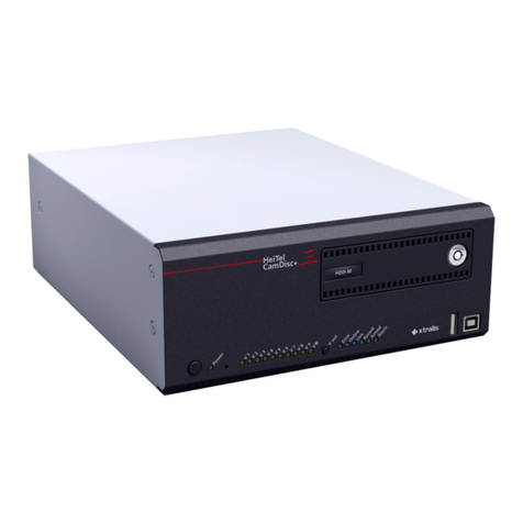
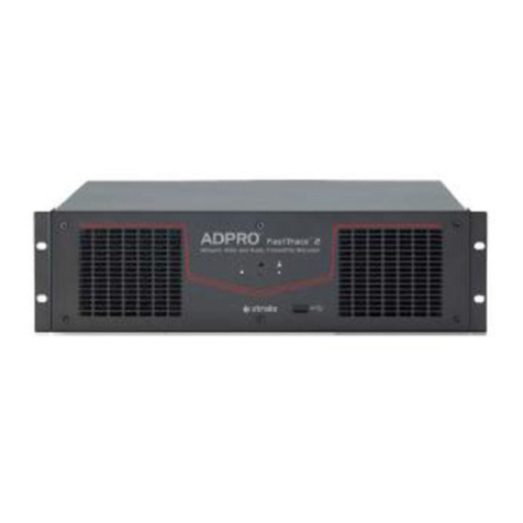
Xtralis ADPRO V3100 Hybrid User manual

ADPRO V3100 Hybrid
Video Security System
ADPRO V3100 Hybrid
video security system
manual
until version 2.00.xxxx
Original Document V1.03
Art. nr. 19531902
Published September 2009
Latest Update February 2011
Xtralis. The sooner you know
SECURITY SOLUTIONS

This manual holds the description of the steps that should be followed to configure the
ADPRO V3100 HYBRID system. All official partners of Xtralis are allowed to use this manual
and to copy it according to their needs.
Great efforts have been made to provide a complete and correct manual on the date of issue.
Nevertheless, Xtralis does not assume any responsibility neither for the use of it nor for the
possible consequences of the use.
Xtralis reserves the right to introduce modifications to the system in general without prior
notice.

Table of contents.
1FEATURES..................................................................................................................................................................... 6
1.1 TECHNICAL SPECIFICATIONS.................................................................................................................................... 7
1.2 CURRENT CONSUMPTION ....................................................................................................................................... 10
1.3 FAN SPEED SELECTION........................................................................................................................................... 11
1.4 EXTENSION BOARDS .............................................................................................................................................. 11
2DESKTOP MODEL ...................................................................................................................................................... 13
2.1 WITH ASUS M2A-VM MOTHERBOARD (ONLY SUPPORTS SOFTWARE VERSIONS UP TO V1.01 -V3100FT).......... 13
2.1.1 Network/monitor/keyboard ........................................................................................................................... 13
2.1.2 Extensions slots - model with Asus M2A-VM motherboard .......................................................................... 13
2.2 WITH INTEL DG31PR MOTHERBOARD................................................................................................................... 14
2.2.1 Network/monitor/keyboard ........................................................................................................................... 14
2.2.2 Extensions slots - model with Intel DG motherboard ................................................................................... 14
2.3 WITH INTEL DG41TY MOTHERBOARD.................................................................................................................. 15
2.3.1 Network/monitor/keyboard ........................................................................................................................... 15
2.3.2 Extensions slots - model with Intel DG motherboard ................................................................................... 15
2.4 OCTOPUS CABLE .................................................................................................................................................... 16
2.4.1 Ferrite Core .................................................................................................................................................. 16
319-INCH MODEL......................................................................................................................................................... 17
3.1 WITH ASUS M2A-VM MOTHERBOARD (ONLY SUPPORTS SOFTWARE VERSIONS UP TO V1.01 -V3100FT)........... 17
3.1.1 Network/monitor/keyboard ........................................................................................................................... 17
3.1.2 Extensions slots - model with Asus M2A-VM motherboard .......................................................................... 17
3.2 WITH INTEL DG31PR MOTHERBOARD................................................................................................................... 18
3.2.1 Network/monitor/keyboard ........................................................................................................................... 18
3.2.2 Extensions slots - model with Intel DG motherboard ................................................................................... 18
3.3 WITH INTEL DG41TY MOTHERBOARD.................................................................................................................. 19
3.3.1 Network/monitor/keyboard ........................................................................................................................... 19
3.3.2 Extensions slots - model with Intel DG motherboard ................................................................................... 19
3.4 WITH INTEL DH55TC MOTHERBOARD .................................................................................................................. 20
3.4.1 Network/monitor/keyboard ........................................................................................................................... 20
3.4.2 Extensions slots - model with Intel DH55TC motherboard........................................................................... 20
3.5 VIDEO &AUDIO CONNECTIONS ............................................................................................................................. 21
3.6 FRONT LED INDICATORS (19" VERSION ONLY)...................................................................................................... 22
3.7 DTC BOARD........................................................................................................................................................... 22
3.8 MOUNTING BRACKETS ........................................................................................................................................... 22
4AVAILABLE CONFIGURATIONS................................................................................................................................ 23
5SETUP AND CONFIGURATION OF A V3100 SYSTEM............................................................................................. 25
5.1 V3100 CLIENT SOFTWARE -MINIMUM SYSTEM REQUIREMENTS ............................................................................ 25
5.2 INSTALLATION OF THE CLIENT SOFTWARE ON YOUR COMPUTER............................................................................ 26
5.3 LAUNCH APPLICATION IN IE .................................................................................................................................. 28
5.4 LAUNCH V3100 CLIENT SOFTWARE IN ITS OWN WINDOW ...................................................................................... 29
5.4.1 To add a V3100 system to the list.................................................................................................................. 29
6USERS........................................................................................................................................................................... 30
6.1 STRONG PASSWORDS ............................................................................................................................................. 30
6.2 USER RIGHTS ......................................................................................................................................................... 31
6.3 AUTHORIZE THE TECHNICIAN................................................................................................................................. 31
7NETWORK CONNECTIONS........................................................................................................................................ 32
8SET UP AN IP CAMERA.............................................................................................................................................. 35
8.1 CONFIGURE AND UPDATE HIPI CARD..................................................................................................................... 37
8.2 SUPPORTED IP CAMERAS (H.264).......................................................................................................................... 38
9SET UP AN ANALOGUE CAMERA............................................................................................................................. 40
9.1.1 PTZ settings................................................................................................................................................... 42

9.1.1.1 Serial PTZ ................................................................................................................................................. 42
9.1.1.2 List of available PTZ protocols................................................................................................................. 43
9.1.1.3 DTC PTZ................................................................................................................................................... 45
9.1.2 Video input termination (75 Ohms/High impedance) ................................................................................... 45
9.1.3 Audio in......................................................................................................................................................... 46
9.1.3.1 Recommended microphones ..................................................................................................................... 47
9.1.4 Audio Out...................................................................................................................................................... 49
9.1.4.1 Connection of VM22A audio switch to V3100 system............................................................................. 50
10 VIDEO MONITOR........................................................................................................................................................ 51
10.1 CONNECTION ......................................................................................................................................................... 51
10.2 CONFIGURATION.................................................................................................................................................... 51
11 CONFIGURE OTB IO (MAIN IO & EXTENSION IO CARD)..................................................................................... 52
11.1 UPDATE MIO CARD ............................................................................................................................................... 52
11.1.1 OTB IO address range .................................................................................................................................. 53
12 NETWORK IO MODULES........................................................................................................................................... 54
12.1 NETWORK IO MODULES:ADDRESS RANGE............................................................................................................. 54
12.1.1 Network IO INPUT / OUTPUT ADDRESSES............................................................................................... 55
12.2 ADD A NETWORK IO MODULE WITH KNOWN IP ADDRESS ...................................................................................... 56
12.3 SEARCH FOR NETWORK IO MODULES ON THE LOCAL NETWORK ............................................................................ 56
12.4 MODIFY SETTINGS OF A NETWORK IO MODULE ..................................................................................................... 57
12.5 PROGRAM NETWORK INPUTS AND OUTPUTS........................................................................................................... 58
13 ALARM TRANSMISSION ............................................................................................................................................. 59
14 ARM/DISARM VIDEO SYSTEM................................................................................................................................... 61
14.1 ARM/DISARM SCHEDULE........................................................................................................................................ 61
14.2 ARM/DISARM SWITCH ............................................................................................................................................ 62
15 ALARM INPUTS........................................................................................................................................................... 62
16 ALARM PROFILES (BEHAVIOUR OF ALARM TRANSMISSION)............................................................................. 64
17 MODE OF OPERATION (BEHAVIOUR OF RECORDINGS)..................................................................................... 65
17.1 MODE SCHEDULE................................................................................................................................................... 65
17.2 ADDITIONAL SETTINGS .......................................................................................................................................... 65
18 ACTIVATE OUTPUTS.................................................................................................................................................. 66
19 VIDEO IC (INTERCONNECTION WITH S3100 SYSTEMS)....................................................................................... 67
20 EMAIL SERVER............................................................................................................................................................ 68
20.1 ADD RECIPIENTS .................................................................................................................................................... 68
21 SET TIME ZONE, TIME AND DATE ........................................................................................................................... 69
22 STORE/ACTIVATE A CONFIGURATION ................................................................................................................... 70
23 LIVE.............................................................................................................................................................................. 71
23.1 PTZ SHORTCUT KEYS............................................................................................................................................. 73
24 CREATE CONTINUOUS RECORDING ...................................................................................................................... 74
25 CREATE RECORDING ON EVENT............................................................................................................................. 76
25.1 ADD HOLIDAYS...................................................................................................................................................... 78
26 VIDEO MOTION DETECTION (VMD) ....................................................................................................................... 79
27 PRIVATE ZONES.......................................................................................................................................................... 80
28 DETECT THE OBSTRUCTION OF THE CAMERA LENS.......................................................................................... 81
29 LOITERING.................................................................................................................................................................. 82

30 SEARCH A RECORDING ON THE VIDEO SYSTEM'S HARD DISK ......................................................................... 83
30.1 TYPES OF RECORDINGS .......................................................................................................................................... 83
30.2 TIME LINE .............................................................................................................................................................. 84
30.3 LOOK UP RECORDINGS BY EVENT........................................................................................................................... 86
30.4 SYNCHRONISED PLAYBACK.................................................................................................................................... 87
31 POST MOTION............................................................................................................................................................. 88
31.1 RESULT.................................................................................................................................................................. 89
31.2 MANAGEMENT OF LOCAL VIDEO RECORDINGS....................................................................................................... 90
32 LOGBOOK.................................................................................................................................................................... 91
32.1 EXAMPLE OF A LOG RECORD.................................................................................................................................. 92
32.2 EXAMPLE OF A EVENT RECORD.............................................................................................................................. 92
32.3 EXAMPLE OF A COMMAND RECORD....................................................................................................................... 92
33 SET THE MAXIMUM DAYS OF VIDEO RECORDING .............................................................................................. 93
34 FIRMWARE, LICENSE, CONFIGURATION FILES.................................................................................................... 94
34.1 SYSTEM LICENSE (FROM VERSION V3100HYB V02.00.0000)............................................................................... 95
34.2 LICENSE TYPES ...................................................................................................................................................... 96
35 VIDEO BACKUP.......................................................................................................................................................... 97
35.1 BURN FOOTAGE STORED ON LOCAL COMPUTER (SEE ALSO CHAPTER 31.2) ............................................................ 98
36 STATUS......................................................................................................................................................................... 99
36.1 ISOLATE AN ALARM INPUT ..................................................................................................................................... 99
36.2 ACTIVATE AN OUTPUT ......................................................................................................................................... 100
36.3 GENERAL STATUS OF THE VIDEO SYSTEM ............................................................................................................ 101
37 CAMERA RECORDING INFORMATION.................................................................................................................. 102
38 ABOUT........................................................................................................................................................................ 103
39 PRESIDIUM HIGH LEVEL INTERFACE.................................................................................................................. 104
40 ADVANCED INFORMATION.................................................................................................................................... 105
40.1 FIND THE SERVER'S IP ADDRESS........................................................................................................................... 105
40.2 INSTALLATION /MAJOR UPDATE PROCEDURE USING AN USB INSTALLER STICK (FOR VERSION 1.00 AND 1.01
ONLY). 106
40.3 V3100 HYBRID INSTALLATION AND V3100FT TO HYBRID UPDATE PROCEDURE:(VERSION 1.02 AND HIGHER) 107
40.4 V3100 HYBRID VERSION 2INSTALLATION AND V3100HYBRID UPDATE PROCEDURE:(VERSION 1.02 AND HIGHER
TO VERSION 2.XX)............................................................................................................................................................ 109
40.4.1 For Asus: not supported.............................................................................................................................. 109
40.4.2 For Intel DG31PR and DG41TY................................................................................................................. 109
40.4.2.1 Installation V3100HYB Version 2...................................................................................................... 109
40.4.2.2 Upgrade V3100HYB Version 1 to V3100HYB Version 2 ................................................................. 111
40.4.3 For Intel DH55TC....................................................................................................................................... 112
40.5 CAMERA URLS.................................................................................................................................................... 114
40.5.1 Parameters.................................................................................................................................................. 114
40.6 REQUIRED HARD DISK SPACE ............................................................................................................................... 115
40.7 NETWORK LOAD .................................................................................................................................................. 115
40.8 V3100 BIOS SETTINGS........................................................................................................................................ 116
40.8.1 Motherboard M2A-VM................................................................................................................................ 116
40.8.2 Motherboard DG31PR and DG41TY.......................................................................................................... 116
40.8.3 Motherboard DH55TC................................................................................................................................ 117
40.9 DIAGNOSTICS....................................................................................................................................................... 117
41 REPAIR/UPDATE PROCEDURE .............................................................................................................................. 118
41.1 REPLACE MOTHERBOARD .................................................................................................................................... 118
41.2 REPLACE/ADD HARD DISK.................................................................................................................................... 118
41.3 REPLACE/ADD VIDEO CARD.................................................................................................................................. 119

41.3.1 Replace a video card................................................................................................................................... 119
41.3.2 Add a video card ......................................................................................................................................... 119
41.4 BIOS UPDATE PROCEDURE (ASUS M2A-VM BOARD)........................................................................................ 120
42 APPLICATION NOTES V3100................................................................................................................................... 121
42.1 VSKWIN:RETRIEVE THE V3100 CONFIGURATION FILE ....................................................................................... 121
42.2 VSKWIN :CREATE AN ALARM TEXT THAT AUTOMATICALLY OPENS A LIVE CAMERA IMAGE .............................. 121
42.3 ACTIVATE TIMER OUTPUT ON V3100................................................................................................................... 122
43 LABELLING OF PRODUCTS.................................................................................................................................... 123
43.1 PRODUCT NUMBER STRUCTURE............................................................................................................................ 124
44 VBG (GERMANY): INSTALLATION INSTRUCTIONS.............................................................................................. 125
44.1 V3100 CLIENT SOFTWARE -MINIMUM SYSTEM REQUIREMENTS .......................................................................... 125
44.2 INSTALLATION OF THE CLIENT SOFTWARE ON YOUR COMPUTER.......................................................................... 125
44.3 USERS.................................................................................................................................................................. 127
44.4 RECORDING BEHAVIOUR...................................................................................................................................... 127
44.5 VIDEO INPUTS ...................................................................................................................................................... 128
44.6 INPUTS/OUTPUTS.................................................................................................................................................. 128
44.7 WATCHING LIVE CAMERAS AND TAKE A SNAPSHOT............................................................................................. 129
44.8 VIDEO BACKUP.................................................................................................................................................... 131
44.9 BURN FOOTAGE STORED ON LOCAL COMPUTER (SEE ALSO CHAPTER 31.2) .......................................................... 132
44.10 LOG OFF PROTECTION .......................................................................................................................................... 132
44.11 HINWEISE............................................................................................................................................................. 133

Safety instructions
CAUTION
RISK OF ELECTRIC
SHOCK, DO NOT OPEN!
CAUTION: TO REDUCE THE RISK OF ELECTRICAL SHOCK, DO NOT REMOVE COVERS. NO USER
SERVICEABLE PARTS INSIDE. REFER SERVICING TO QUALIFIED SERVICE PERSONNEL.
WARNING: TO REDUCE THE RISK OF FIRE OR ELECTRIC SHOCK, DO NOT EXPOSE THIS APPLIANCE
TO RAIN OR MOISTURE.
The lightning flash with an arrowhead symbol within an equilateral triangle is intended to
alert the user to the presence of uninsulated “dangerous voltage” within the product’s
enclosure that may be of sufficient magnitude to constitute a risk of electric shock to
persons.
The exclamation point within an equilateral triangle is intended to alert the user to
presence of important operating and maintenance (servicing) instructions in the literature
accompanying the appliance.

ADPRO V3100 Hybrid video system
Technical manual
- 6 -
1 Features
V3100 Hybrid
Accepts analogue cameras and IP cameras, up to 16 in total. For analogue cameras, one or
two A/V cards have to be inserted. Two different A/V cards are available; one with 4 A/V
inputs and one with 8 A/V inputs. For IP cameras, a HIPI card will be required. Up to 2 HIPI
cards can be installed. Each HIPI card can handle up to 8 IP cameras. A/V cards and HIPI
cards can be mixed, but the maximum number of cameras is always limited to 16.
Down the coax PTZ control through an optional DTC card (for 19 inch model only)
Real Time compression
Integrated Web configuration and visualisation
OTB I/O (On The Box Inputs & Outputs)
Internal Main IO card (MIO) and Extension IO card (EIO), offering 20 balanced inputs, 8 relay
outputs and control signals for either VM22A equipment (audio output switcher) or PTZ
cameras (RS485 output)
Second set with Main IO and Extension IO card, doubles the number of inputs to 40 and
outputs to 16, and adds an output for PTZ cameras.
Up to 8 Ethernet I/O modules with PoE
Din Rail installation
Connects to the local IP network
4 to 16 digital inputs per module
4 to 16 relay outputs NC/NO per module
three Led's for operational status of V3100 Hybrid
Watchdog and sounder
Multi-site V3100 configuration
Integration of up to 10.000 V3100 video security systems
Remote video and audio, live video and consultation of recordings
Compatibility with S3100, Presidium, VSKwin®,VCP and M3000
SDK for third party integration

ADPRO V3100 Hybrid video system
Technical manual
- 7 -
1.1 Technical specifications
Max number of cameras
16 (analogue and IP cameras all together)
Analogue cameras
4, 8, 12 or 16 analogue A/V inputs
Video
PAL or NTSC
BNC connectors (1.0 Vp-p; 75 Ohm)
Max. Cable length: 350m (with RG59); 610m (with
RG11)
Audio
1 input per analogue camera
BNC on desktop; screw connectors on 19" model
input level: 2.0 Vp-p, 1000 Ohm
IP cameras
up to 16 IP cameras on dedicated IP network.
Requires an optional network interface (one HIPI card for
8 IP cameras). Only cameras which can handle H264
video streaming can be used. Cameras with audio input
are supported.
Video output
VGA connector; adjustable resolution (up to SXGA)
Video compression
H.264
Analogue cameras
Video resolution (PAL)
176 x 144 (QCIF)
352 x 288 (CIF)
704 x 288 (2CIF)
528 x 384 (DCIF)
704 x 576 (4CIF)
Analogue cameras
Video resolution (NTSC)
176 x 120 (QSIF)
352 x 240 (SIF)
704 x 240 (2SIF)
528 x 320 (DSIF)
704 x 480 (4SIF)
Analogue cameras
Images/second
CIF, 2CIF, DCIF (PAL): 25 ips/camera
SIF, 2SIF, DSIF (NTSC): 30 ips/camera
4CIF (PAL): 15 ips/camera
4SIF (NTSC): 15 ips/camera
IP cameras
Video resolution and ips
depends on camera type, up to HD resolution
Bandwidth consumption
6 ips CIF/SIF: 70kb/sec, 12ips 4CIF/4SIF:
400kb/sec in optimum quality
Bandwidth
Remotely adjustable: compression, ips and quality
A bandwidth limit can be specified
Motion detection
4 zones adjustable per camera
Analogue cameras
Audio compression
OggVorbis Codec 16Kbps
IP cameras
Audio compression
depends on type of camera
Relay outputs
4 relay outputs on MAIN I/O card; 4 relay outputs on
EXTENSION I/O card
Command inputs
8 monitored inputs on Main I/O card; 12 monitored inputs
on EXTENSION I/O card
External I/O
Up to 128 inputs and 128 outputs through Ethernet IO
modules

ADPRO V3100 Hybrid video system
Technical manual
- 8 -
System
PC platform - Linux OS
Network protocols
TCP, UDP, TELNET, HTTP, SMTP, RTSP, RTP, NTP...
Application update
Local and remote
Web server
Integrated
COM ports
4 USB interfaces, used for:
PTZ control (requires an USB to RS485 convertor)
modem (PSTN or ISDN)
Ethernet
10/100/1000 Base-T, auto detection,
full duplex, RJ45
Storage
Up to 4 devices (connected through SATA interfaces),
following arrangements are possible:
1 to 4 internal hard disks (500GB to 2TB)
For the standard 19” model and the desktop model: an
external USB DVD writer or USB memory stick. The USB
connector is accessible on the back.
For the small 19” model, an external USB DVD writer or
USB memory stick; the USB connector is accessible on
the front.
Recording type
Continuous, event (input, motion detection,..)
Alarm over IP (S3100), Presidium
Remote visualisation
Internet Explorer; Windows XP, Vista, Windows 7
Server 2003
PTZ cameras
Yes, extensive list available - see chapter 9.1.1
Management
Internet browser (installs a V3100 Client)
VSKwin software
M3000 software
Power supply
100~240 VAC, 50/60 Hz (+80% efficiency)
THE PANEL HAS TO BE CONNECTED TO A 230VAC/16A
MAINS OUTLET WITH PROPER EARTH, APPLYING A
SEPARATE LOCALLY APPROVED POWER CORD!
Operating temperature
5 ~ 40°C (also read chapter 1.3)
Humidity
20 ~ 93% (non-condensing)
Dimensions
desktop model: without feet: 450 x 135 x 420mm
(WxHxD)
with feet: 450 x 145 x 420mm (WxHxD)
19" model 445 x 132.5 x 500 (WxHxD) (without
brackets)
19" S (small) 445 x 132.5 x 300 (WxHxD) (without
brackets)
445 x 135 x 300 (WxHxD) (with
adhesive rubber feet fixed on the
bottom to use it as desktop unit; feet
are included)

ADPRO V3100 Hybrid video system
Technical manual
- 9 -
Limitations on live video streaming
There is one separate video processor for each group of 4 analogue cameras (video in 1-4, 5-8, 9-12, 13-16). If
4CIF resolution is applied to at least one camera within the same group, following limitations will apply to live
streaming within this group of cameras (due to processor limits):
number of
enabled
cameras within
the same group
Live streaming quality
1 to 2
no limits
3
select only QCIF or CIF (25 ips); or same quality as recording (hard
disk stream)
4
select only QCIF (25 ips) or same quality as recording (hard disk
stream)
Live streaming quality is programmed under System > CONNECTIONS > Video inputs > Network:
Default Live preset.

ADPRO V3100 Hybrid video system
Technical manual
- 10 -
1.2 Current consumption
Estimated current consumption depends on which components have been installed and on the system load:
Motherboard
12W (Asus) / 16W (Intel)
Processor
25W (Asus: 45W max.) (Intel DG31 &
DG41: 65W max.)(Intel DH55: 73W max)
4-channel video/audio card
3.5W
8-channel video/audio card
7W
Western digital RE hard disk
11W
Western digital RE2 hard disk
12W
Main I/O card
1W
Extension I/O card
1W
HIPI card (for IP cameras)
3W
DTC card
0,5W
Example
Motherboard
12W
Processor
25W
4x WD RE2
48W
2x 8-channel V/A card
14W
2x I/O card
2W
Total
101W (on secondary)
On mains input (total current consumption
divided by 0.8, which is the efficiency of the
PS)
126W (on primary)
(0.53A/230VAC)

ADPRO V3100 Hybrid video system
Technical manual
- 11 -
1.3 Fan speed selection
Two large fans are provided to dissipate the heat. The fans have a switch to select the speed: low/medium/fast.
To set the fan speed, consult the following table
ambient temperature <30°C
ambient temperature >30°C
Asus motherboard
low
fast
Intel motherboard
(19" model)
medium
fast
Intel motherboard
(19" S model)
medium
medium
Intel motherboard
(desktop model)
medium
fast
1.4 Extension boards
Type
Description
See datasheet for more details
HIPI
PCI Express extension board for 8 IP cameras
195x1930
4ch/8ch
DS40xx
PCI extension board for 4 or 8 analogue cameras, including
audio inputs
4ch/8ch
DS42xx
PCI Express extension board for 4 or 8 analogue cameras,
including audio inputs
MIO
Main Input Output board: USB extension board, inserted in a
free PCI or PCI Express connector
195x1920
EIO
Extension Input Output board: extension board, inserted in a
free PCI or PCI Express connector and linked to the MIO board,
extending the number of inputs and outputs.
195x1920
x= 0 (Dutch), 1 (French), 3
(English)
HIPI EIO MIO 4 Ch 8 Ch
1 2 3 4 5 6 7 8 9 10 11 12 13 14 15 16 17 18 19 20 21 22 23 24 25
26 27 28 29 30 31 32 33 34 35 36 37 38 39 40 41 42 43 44 45 46 47 48 49 50
ETHERNET
CHANNEL 1…...4
CHANNEL 1…...4
CHANNEL 5…...8
IN1
IN2
0V
IN3
IN4
0V
IN5
IN6
0V
IN7
IN8
0V
TA/STROBE
TB/AUDIO OUT
0V
RA/CLOCK
RB/DATA
OUT1
OUT1
OUT2
OUT2
OUT3
OUT3
OUT4
OUT4
IN9
IN10
0V
IN11
IN12
0V
IN13
IN14
0V
IN15
IN16
0V
OUT5
OUT5
OUT6
OUT6
OUT7
OUT7
OUT8
OUT8
IN17
IN18
IN19
IN20
0V

ADPRO V3100 Hybrid video system
Technical manual
- 12 -
General rules
The desktop model offers 4 extension slots: two PCI Express slots and two PCI slots.
The 19" model offers 6 extension slots.
For Asus M2A-VM, Intel DG31PR and Intel DG41TY motherboard: two PCI Express slots, two PCI slots and
two physical slots.
For Intel DH55TC motherboard: three PCI Express slots, one PCI slots and two physical slots.
The HIPI cards can only be inserted in a PCI Express slot.
The A/V cards type DS40xx requires a PCI slot.
The A/V cards type DS42xx requires a PCI Express slot.
MIO and EIO cards can be inserted anywhere (any free slot left unused); the MIO card is connected to an
internal USB connector and the EIO card is connected to the MIO card through a flat cable.

ADPRO V3100 Hybrid video system
Technical manual
- 13 -
2 Desktop model
2.1 With ASUS M2A-VM motherboard (only supports software versions
up to V1.01 - V3100FT)
26 27 28 29 30 31 32 33 34 35 36 37 38 39 40 41 42 43 44 45 46 47 48 49 50
1 2 3 4 5 6 7 8 9 10 11 12 13 14 15 16 17 18 19 20 21 22 23 24 25
Slot 1
Slot 2
Slot 4
Slot 3
BNC1→4BNC5→8
BNC9→12 BNC13→16
BNC1→4 BNC5→8
BNC1→4
4 analogue
cameras 8 analogue
cameras
BNC9→12
BNC1→4
12 analogue
cameras
BNC5→8
2.1.1 Network/monitor/keyboard
/dev/ttyU1
/dev/ttyU2/dev/ttyU3
/dev/ttyU4
ASUS M2A-VM
/dev/ttyU1 is reserved for an external modem
LINE IN
SPK
MIC
MOUSE
VGADVI-D
LAN
KEYBOARD
NOT USED
2.1.2 Extensions slots - model with Asus M2A-VM motherboard
Slots
Slot 1
Slot 2
Slot 3
Slot 4
Type
PCI Express
PCI
PCI
PCI Express
Accepts
MIO/EIO
Accepts
MIO/EIO/4CH
AV or 8CH
AV
Accepts
MIO/EIO/4CH
AV or 8CH
AV
Accepts
MIO/EIO

ADPRO V3100 Hybrid video system
Technical manual
- 14 -
2.2 With Intel DG31PR motherboard
26 27 28 29 30 31 32 33 34 35 36 37 38 39 40 41 42 43 44 45 46 47 48 49 50
1 2 3 4 5 6 7 8 9 10 11 12 13 14 15 16 17 18 19 20 21 22 23 24 25
KEYBOARD
Slot 1
Slot 2
Slot 4
Slot 3
BNC1→4BNC5→8
BNC9→12 BNC13→16
BNC1→4
BNC1→4
4 analogue
cameras 8 analogue
cameras
BNC1→4
BNC5→8BNC9→12
12 analogue
cameras
BNC5→8
2.2.1 Network/monitor/keyboard
/dev/ttyU1
/dev/ttyU2
/dev/ttyU3
/dev/ttyU4
INTEL DG31PR
/dev/ttyU1 is reserved for an external modem
KEYBOARD
2.2.2 Extensions slots - model with Intel DG motherboard
Slots
Slot 1
Slot 2
Slot 3 (*)
Slot 4
Type
PCI Express
PCI Express
PCI
PCI
Accepts
MIO/EIO or
HIPI (ETH1)
for 8 IP
cameras
Accepts
MIO/EIO or
HIPI (ETH2)
for 8 IP
cameras
Accepts
MIO/EIO/4CH
AV or 8CH
AV
Accepts
MIO/EIO/8CH
AV
(*) put the 4-channel AV card only in this slot!!

ADPRO V3100 Hybrid video system
Technical manual
- 15 -
2.3 With Intel DG41TY motherboard
26 27 28 29 30 31 32 33 34 35 36 37 38 39 40 41 42 43 44 45 46 47 48 49 50
1 2 3 4 5 6 7 8 9 10 11 12 13 14 15 16 17 18 19 20 21 22 23 24 25
/dev/ttyU1
MODEM
Slot 1
Slot 2
Slot 4
Slot 3
BNC9→12 BNC13→16
BNC1→4 BNC5→8
BNC1→4
BNC1→4
4 analogue
cameras 8 analogue
cameras
BNC1→4
BNC5→8BNC9→12
12 analogue
cameras
BNC5→8
MOUSE
KEYBOARD
SPEAKER
LINE IN
LAN
USB
MIC
VGA (MONITOR)
/dev/ttyU2
/dev/ttyU3
/dev/ttyU4
2.3.1 Network/monitor/keyboard
/dev/ttyU1
MODEM
MOUSE
KEYBOARD
SPEAKER
LINE IN
LAN
USB
MIC
VGA (MONITOR)
/dev/ttyU2
/dev/ttyU3
/dev/ttyU4
2.3.2 Extensions slots - model with Intel DG motherboard
Slots
Slot 1
Slot 2
Slot 3 (*)
Slot 4
Type
PCI Express
PCI Express
PCI
PCI
Accepts
MIO/EIO or
HIPI (ETH1)
for 8 IP
cameras
Accepts
MIO/EIO or
HIPI (ETH2)
for 8 IP
cameras
Accepts
MIO/EIO/4CH
AV or 8CH
AV
Accepts
MIO/EIO/8CH
AV
(*) put the 4-channel AV card only in this slot!!

ADPRO V3100 Hybrid video system
Technical manual
- 16 -
2.4 Octopus cable
On the desktop model, video and audio sources apply a specific cable. All inputs use BNC connectors.
CHANNEL 1…...4CHANNEL 5…...8
8 Ch or 4 Ch
VID1
VID2
VID3
VID4
AUD1
AUD2
AUD3
AUD4
2.4.1 Ferrite Core
The supplied ferrite cores are clipped onto the octopus cables in order to suppress high frequency noise - see
figure.
+/- 1cm

ADPRO V3100 Hybrid video system
Technical manual
- 17 -
3 19-inch model
3.1 With Asus M2A-VM motherboard (only supports software versions
up to V1.01 - V3100FT)
ATX board
POWER SWITCH
V1
V2
V3
V4
V5
V6
V7
V8
V9
V10
V11
V12
V13
V14
V15
V16
A1
GND
A2
GND
A3
GND
A4
GND
A5
GND
A6
GND
A7
GND
A8
GND
A9
GND
A10
GND
A11
GND
A12
GND
A13
GND
A14
GND
A15
GND
A16
GND
MAINS INLET
ETHERNET
THROUGH-
CONNECTION
(AVAILABLE ON
FRONT)
Video/Audio Inputs
1 2 3 4 5 6 7 8 9 10 11 12 13 14 15 16 17 18 19 20 21 22 23 24 25
26 27 28 29 30 31 32 33 34 35 36 37 38 39 40 41 42 43 44 45 46 47 48 49 50
1 2 3 4 5 6 7 8 9 10 11 12 13 14 15 16 17 18 19 20 21 22 23 24 25
26 27 28 29 30 31 32 33 34 35 36 37 38 39 40 41 42 43 44 45 46 47 48 49 50
Slot 1
Slot 2
Slot 3
Slot 4
Slot 5
Slot 6
The installation of the 19" model in a rack requires safety precautions regarding the way of disconnection from
the mains circuit.
3.1.1 Network/monitor/keyboard
/dev/ttyU1
/dev/ttyU2/dev/ttyU3
/dev/ttyU4
ASUS M2A-VM
/dev/ttyU1 is reserved for an external modem
LINE IN
SPK
MIC
MOUSE
VGADVI-D
LAN
KEYBOARD
NOT USED
3.1.2 Extensions slots - model with Asus M2A-VM motherboard
Slots
Slot 1
Slot 2
Slot 3
Slot 4
Slot 5 (19"
only)
Slot 6 (19"
only)
Type
PCI Express
PCI
PCI
PCI Express
Accepts
MIO/EIO
Accepts
MIO/EIO/4CH
AV or 8CH
AV (lowest
camera
number
(cam1 ► 4/8)
Accepts
MIO/EIO/4CH
AV or 8CH
AV (highest
camera
numbers
(from cam
5/9 ►16)
Accepts
MIO/EIO
Accepts EIO
Accepts MIO

ADPRO V3100 Hybrid video system
Technical manual
- 18 -
3.2 With Intel DG31PR motherboard
POWER SWITCH
V1
V2
V3
V4
V5
V6
V7
V8
V9
V10
V11
V12
V13
V14
V15
V16
A1
GND
A2
GND
A3
GND
A4
GND
A5
GND
A6
GND
A7
GND
A8
GND
A9
GND
A10
GND
A11
GND
A12
GND
A13
GND
A14
GND
A15
GND
A16
GND
MAINS INLET
ETHERNET
THROUGH-
CONNECTION
(AVAILABLE ON
FRONT)
Video/Audio Inputs
26 27 28 29 30 31 32 33 34 35 36 37 38 39 40 41 42 43 44 45 46 47 48 49 50
1 2 3 4 5 6 7 8 9 10 11 12 13 14 15 16 17 18 19 20 21 22 23 24 25
1 2 3 4 5 6 7 8 9 10 11 12 13 14 15 16 17 18 19 20 21 22 23 24 25
26 27 28 29 30 31 32 33 34 35 36 37 38 39 40 41 42 43 44 45 46 47 48 49 50
KEYBOARD
Slot 1
Slot 2
Slot 3
Slot 4
Slot 5
Slot 6
3.2.1 Network/monitor/keyboard
/dev/ttyU1
/dev/ttyU2
/dev/ttyU3
/dev/ttyU4
INTEL DG31PR
/dev/ttyU1 is reserved for an external modem
KEYBOARD
3.2.2 Extensions slots - model with Intel DG motherboard
Slots
Slot 1
Slot 2
Slot 3 (*)
Slot 4
Slot 5 (19"
only)
Slot 6 (19"
only)
Type
PCI Express
PCI Express
PCI
PCI
Accepts
MIO/EIO or
HIPI (ETH1)
for 8 IP
cameras
Accepts
MIO/EIO or
HIPI (ETH2)
for 8 IP
cameras
Accepts
MIO/EIO/4CH
AV or 8CH
AV (highest
camera
numbers
(from cam
5/9 ►16)
Accepts
MIO/EIO/8CH
AV (lowest
camera
number
(cam1 ► 8)
Accepts EIO
Accepts MIO
Table of contents
Other Xtralis Security System manuals
Popular Security System manuals by other brands

weintek
weintek cMT1106X Series installation instructions

Camille Bauer
Camille Bauer SINEAX VC 603 operating instructions

Motorola solutions
Motorola solutions NTN2571 manual

Motorline professional
Motorline professional CSV100 installer and user manual

STI
STI STI-6400 instruction manual

Linear
Linear REMOTE ACCESS SOFTWARE DVS-1200 installation instructions