Xview XVMIRROR User manual

XVMIRROR
USER MANUAL
xviewdrive.com.au
For more information
on the Xview range go
to our website
VIEW
INCLUSIONS:
Dash Cam, GPS Power Cable, 12/24V In-Car USB Charger,
Micro SD Card, Adhesive Surface Mount, Rear Camera &
Rear Camera Cable.

Mirror Display
• 4.3” 16:9 High-resolution TFT LCD Screen
• Resolution 480*272
• Clip-On mount extends 53-70mm
• 12V Compatible
• PAL video standard
• Power Supply: DC12V +/- 10%
• Video Input : Yellow = Reverse Camera Input
• Secondary Video RCA Input
• Dimensions 75(H) x 37(W) x 285mm(L)
Butterfly Camera
• 120 Degree wide angle lens
• Parking guide lines
• IP-67 Dust and water protection
• Surface plate mount
• CMOS Sensors
• 0.2 Lux
• PAL
• 6M Video extension cable
1. PRODUCT FEATURES AND SPECIFICATIONS
2

Product features and specifications......................................2
Table of contents..................................................................3
Installation diagram..............................................................4
Installing the camera............................................................5
Installation of the Mirror Display...........................................7
Testing the reverse camera function....................................7
Menu options and settings..................................................8
Troubleshooting guide.........................................................9
Safety information & warnings...........................................10
Technical assistance..........................................................11
2. TABLE OF CONTENTS
3

F
F
F
F
M
M
F
F
F
F
Moulded
splitter
Moulded
splitter
M
Powerwires
(ACC)
+
M
M
+
Camera
Mirror
6 Metres
(Optional front camera)
(Red wires can
be used for
additional
accessories )
Powerwires
(Reversing light)
The Clip on mirror design securely mounts on the existing rear
view mirror in the vehicle by expanding the clamping arms at the
back. The video signal is transferred from the camera to the
Mirror Display via an RCA cable that will need to be run through
the boot, through the passenger compartment to the mirror
displays wired loom run under the dash. From there the power
and video signals are sent directly to the display. At the rear of
the car the camera is powered directly from the reversing tail
light. Priority is the AV2 input.
3. INSTALLATION DIAGRAM
4

In most instances, the camera is best mounted above the
vehicles license plate as shown here.
1. Connect the RED wire of the Cameras Power Harness to the
wire that supplies power to the reversing light globe (the wire that
is energized only when the car is put into reverse). Before
making the electrical connection, temporarily disconnect the
camera from the power plug whilst making the connection to the
reversing light globe. Use a suitable splicing/crimp connector
(scotch lock type) or strip connector. This connection can also be
soldered, making sure to insulate the joint with electrical
insulation when done. The camera has only one wire to connect
(positive (+). There is no need to hook up a ground earth wire as
the camera gets its earth through the RCA cable. Hooking up the
ground earth may cause a ground loop. In this case horizontal
lines will appear in the image.
NOTE: CAN BUS
In the event that the cars reversing lights are driven by CAN BUS
the above wiring system may not trigger the system correctly. It
may even create a globe fault warning. In this case a CAN BUS
Hole for cable
4. INSTALLING THE CAMERA
5

module (sold separately) may need to be installed. However, just
because the vehicle has a CAN BUS system does not
necessarily mean that it will require such a module to work. In
fact the opposite is true. Most vehicles do not require an
additional module. If a CAN BUS module is required we
recommend seeking advice from a professional installer.
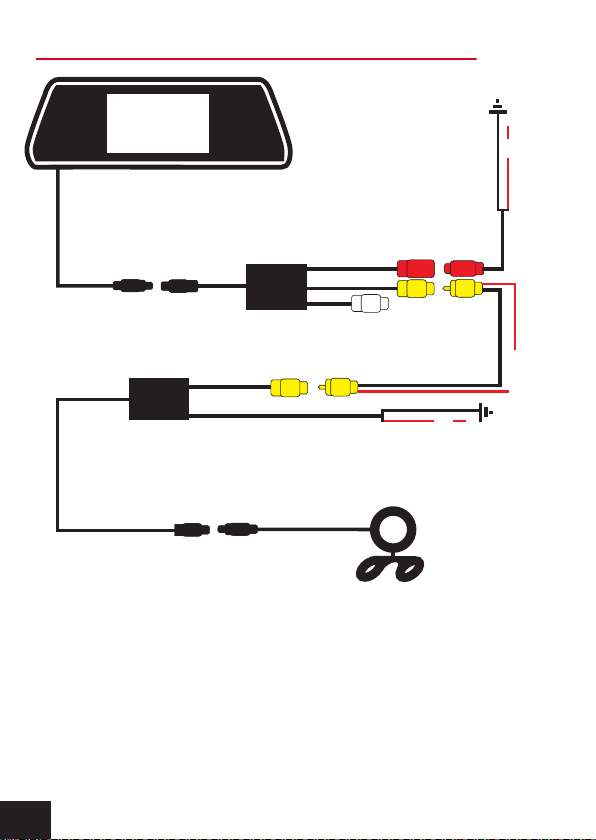
2. After you have insulated the join you can connect the power
harness to the camera.
NOTE:
Some cars that run LED or computer controlled lighting systems
may not deliver enough voltage to run the camera. If the voltage
at the reversing wire light is less than +12 volts it may be
necessary to use a relay to supply power to the transmitter
harness from the wiring in the front of the car. In this case the
reversing light only needs to trigger the relay. Make sure that you
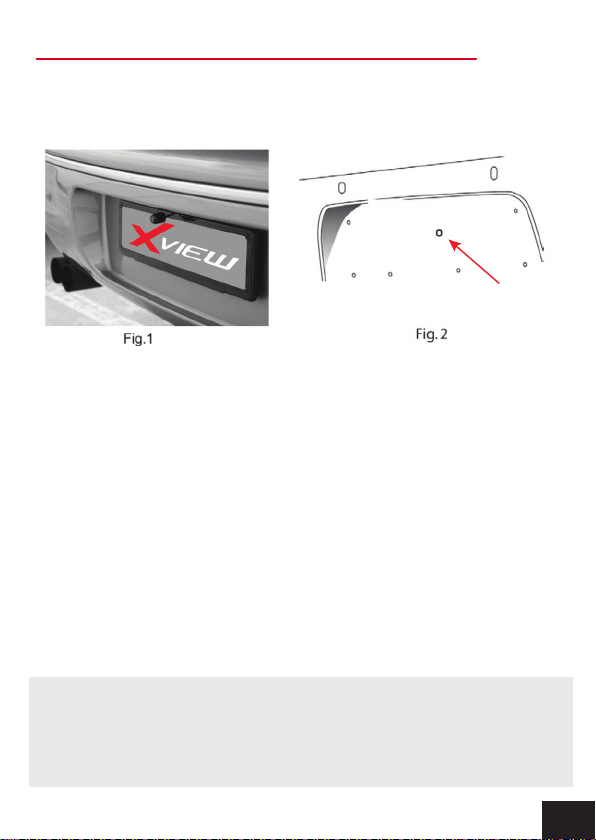
do not drill holes in the panels that have an opposite face that is
visible outside the car for example guard panels. In fact,
whenever drilling holes in the bodywork of a vehicle, always see
what is on the other side.
3. Connect one end of the supplied RCA cable to the RCA socket
from the camera, then run the RCA cable to the front under side
of the driver side dash board. This is where the display’s loom
will be located. To do this you will need to remove the rear seat
to pass the cable into the cabin area and you will need to remove
the door scuff plates to run the wire along the side of the vehicle.
The RCA cable will be hidden when you replace the scuff plates.
When the cable is at the front of the vehicle the RCA cable needs
to be run from the scuff plate area to the underside of the dash
behind the kick trim (remove and run cable).
5. INSTALLING THE CAMERA CONT....
6

4. The display has two power wires to be connected. Connect the
red wire (accessories +12V) to a wire that is energized when the
vehicles accessories is turned on. Connect the black wire to a
ground earth wire or to the body of the car using the steel of the
cars body behind the kick trim as an earth. In this case drill a
small hole and connect the wire using a suitable ring terminal.
Scrape off the cars paint around the hole to ensure good earth.
5. Connect the RCA cable to the RCA socket from the displays
loom.
1. Engage the park brake and turn the ignition key to the on
position. DO NOT start the vehicle.
2. Select reverse gear with the gear shift. The Mirror Display will
sense the video signal from the camera automatically and will
display the camera’s image of the rear of the vehicle.
6. INSTALLATION OF THE MIRROR DISPLAY
7. TESTING THE REVERSE CAMERA FUNCTION
7

- Brightness: Adjusts screen brightness
- Contrast: Adjusts screen contrast
- Saturation: Adjusts screen saturation
- Zoom: Changes display mode between
4:3 & 16:9 ratio
- Language: Select menu language
- Reset: Resets all menu setting back to
factory configuration
1. Press the Middle button for Menu access functions (see Fig.1)
2. Press the Top button repeatedly to increase value
3. Press the Bottom button repeatedly to decrease value
8. MENU OPTIONS AND SETTINGS
8

Problem: The Mirror Display feels warm when it is operating
Solution: • It is normal for the Mirror Display to feel warm to the
touch during typical use.
Problem: My screen image is blurry, dirty or discoloured
Solution: • Check to see if there are any finger prints or dirt
present on the camera lens. If needed, clean with a soft dry
cloth before recording.
• Also be sure to have removed the transparent lens/screen
cover during installation.
Problem: The Mirror Display is frozen or not responding
Solution: • Reset the unit by accessing reset function in the
menu.
Problem: Unresolved issues
Solution: • Reset the unit by accessing reset function in the
menu.
• Contact Gator Technical Department.
9. TROUBLESHOOTING GUIDE
9

Do not use the Mirror display in damp working conditions; the
Mirror Display is not waterproof.
Do not try opening the shell or trying to repair the Mirror Display
by yourself. If the accessories for the Mirror Display have any
problems, please take it to an authorised repair agent for repair.
Do not use a chemical substance, cleaning solvent or cleaner
to clean the Mirror Display, please use a moist soft cloth if you
would like to clean the Mirror Display.
Do not use the Mirror Display under conditions where dust is
present.
Please pay attention to cleaning the lens surface, use a moist
soft cloth to clean the lens before use, to avoid poor video
footage.
10. SAFETY INFORMATION & WARNINGS
10

11. USER SUPPORT
If you need assistance setting up or have an issue regarding
the use of your Xview product contact Xview Customer
Support. Australian Agent:
TEL: 03 – 8587 8898 FAX: 03 – 8587 8866
Mon-Fri 9am – 5pm AEST
For more information, manuals, software or other products in
the Xview range please go to our website.
Xviewdrive.com.au
This manual is considered correct at time of printing but is
subject to change. For latest manuals and updates refer to the
website.
Please retain this user guide for future reference.
11

Table of contents
Other Xview Dashcam manuals