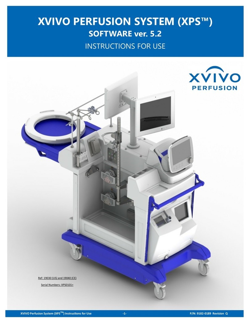
XVIVO Liver Assist User manual

11.01.601.07a EN

11.01.601.7c EN Page 2of 36
Model Numbers:
-11.01.201, 11.01.202, 11.01.203, 11.01.204
Patented
2797
MedEnvoy Switzerland
Gotthardstrasse 28
6302 Zug
Switzerland
XVIVO B.V.
Bornholmstraat 84
9723 AZ Groningen
THE NETHERLANDS
+3150 3131905
info.xnl@xvivogroup.com
www.xvivogroup.com
24/7 Helpdesk (for urgent calls only)
+31 50 3640116

11.01.601.7c EN Page 3 of 40
1Product description 4
1.1 Intended use 5
1.2 Pump unit 5
1.3 Thermo unit 8
1.4 Trolley 10
1.5 Disposable set 11
1.6 Ordering information 12
1.7 Product specifications 13
2Installation 14
3Operation 15
3.1 Preparing the perfusion procedure 15
3.2 Perfusion procedure 22
3.3 In-hospital transport 25
3.4 Stopping the operation 25
4Cleaning 26
4.1 After every procedure 26
4.2 Weekly: disinfection thermo unit 26
4.3 Yearly: decalcifying thermo unit 27
5General safety instructions 28
6Alarms and troubleshooting 30
6.1 Alarm signals 30
6.2 Alarm message explanation 31
6.3 Probable causes 32
7Liability and warranty 32
8Disposal 33
9Classifications 33
9.1 MDD declaration 33
9.2 EMC declarations 34
Appendix A: graphic symbols 37
Appendix B: abbreviations 38

11.01.601.7c EN Page 4 of 40
The Liver Assist, from XVIVO B.V., is a pump system providing temperature controlled dual
oxygenated isolated perfusion of donor livers to bridge the time span between donor
hepatectomy and liver transplantation in the recipient.
The Liver Assist is a modular system consisting of five main modules:
•PV pump unit (for Portal Vein perfusion)
•HA pump unit (for Hepatic Artery perfusion)
•Thermo unit
•Trolley including table top
•Disposable set
The Liver Assist may only be used with the following disposable sets:
•NL40046511, order number: 11.451.
The following reusable accessories are included with the Liver Assist:
•Power cord thermo unit
•Power cord between both (PV & HA) pump units and thermo unit
•Data cable between (PV & HA) pump units and thermo unit
•Pressure sensor cables (2x)
•Temperature sensors (3x)
•Flow sensors (2x)
•Instructions for Use
•Thermo water tubing
•Water tubing couplers (2x)
Figure 1: Liver Assist with pump units, thermo unit, and disposable holder connected to the trolley

11.01.601.7c EN Page 5 of 40
The Liver Assist is intended to be used for isolated temperature controlled ex-situ
oxygenated machine perfusion of donor livers, for a period up to 6 hours.
The Liver Assist is intended for use by trained professionals in a professional healthcare
environment. Users are expected to be familiar with standard medical practices as required
for organ perfusion. There are two types of users of the device
•sterile surgeon, he/she connects the organ to the subsequent tubing of the
disposable set and determinesthe perfusionconditions. After perfusion the surgeon
checks the organ on quality for transplantation and removes the organ from the
device.
•non-sterile perfusionist, he/she prepares the device for use, places and primes the
disposable system, and operates the device during the perfusion period. After
perfusion the perfusionist cleans the device.
Indications for use
Indications for use of the Liver Assist include in-hospital machine perfusion of donor livers
from all deceased donor types as hypothermic to normothermic to preservation instead of
static cold storage or reconditioning after static cold storage, with the intention to improve
transplantation outcome of standard criteria donor livers, or to assess viability of extended
criteria and eligible for discard donor livers.
Figure 2: Front and rear view of the pump units.
1
2
3
4
5
6
7
8
9

11.01.601.7c EN Page 6 of 40
Figure 3: Right and left-hand side view of the pump units
1. Control panel
2. Oxygen cylinder
3. Oxygen cylinder compartment
4. Electrical power inlet
5. Data cable connection
6. USB connection
7. Equipotentiality pin
8. Product label
9. Screw joint
10. Reservoir temperature
connection (T2)
11. Perfusion temperature
connection (T1)
12. Pressure sensor cable
connection
13. Flow sensor connection
14. Magnetic pump coupling
10
11
12
13
14

11.01.601.7c EN Page 7 of 40
Control Panel
Figure 4: Control panel.
Display showing
perfusion
temperature
Pause audible alarm button
Control display,
showing menu and
relevant data
Down button
Pump on/off
indicator
Display showing
actual flow
Attention
indicator
Power
indicator
Pump on/off
button
Power button
Attention
temperature
indicator
OK button
Up button

11.01.601.7c EN Page 8 of 40
Figure 5: Front and rear view of the thermo unit
Figure 6: Right and left-hand side view of the thermo unit
24
25
15
16
17
18
19
21
22
23
20
24

11.01.601.7c EN Page 9 of 40
Figure 7: Accessories thermo unit; quick-connect thermo water connectors, flow indicator, thermo water
coupling tube and tubing
15. Thermo reservoir
16. Electrical power inlet
17. Data cable connection
18. Electrical power outlet
19. Equipotentiality pin
20. Product label
21. Screw connection for fixation
on trolley
22. Thermo water inlet connector
23. Thermo water outlet
connector
24. Air intake vents
25. Air outlet vents
26. Water connector
27. Water tubing coupler
28. Flow indicator
29. Water drainage valve
29a Thermo tubing de-airing
balloon
26
27
28
29
29a

11.01.601.7c EN Page 10 of 40
Figure 8: Trolley
30. Table
31. Organ reservoir holder
32. Push Bar
33. Oxygenator holder
34. Screw holes for connection of
pump and thermo units
35. Product label
36. Pressure sensor holder
30
34
35
31
33
32
36
36

11.01.601.7c EN Page 11 of 40
Figure 9. Disposable set
37. Sterile lid with drape
38. Inner lid
39. Sterile reservoir
40. Filling line PV
41. Pressure sensor PV
42. Temperature sensor T2
connection
43. Sample line PV
44. Oxygenator PV
45. Oxygen line PV
46. Pump head PV
47. Flow sensor tube PV
48. Perfusion lines PV
49. Bile line
50. Filling line HA
51. Pressure sensor HA
52. Sample line HA
53. Oxygen line HA
54. Oxygenator HA
55. Pump head HA
56. Flow sensor tube HA
57. Perfusion lines HA
37
39
41
44
45
46
48
49
42
47
43
40
38
51
53
54
55
57
52
56
50

11.01.601.7c EN Page 12 of 40
The following Liver Assist parts, accessories and single use disposables can be (re)ordered:
Item
Order number
Liver Assist
11.01.101
Pump unit (PV)
11.01.201
Pump unit (HA)
11.01.202
Thermo unit
11.01.203
Trolley
11.01.204
Work table
11.01.212
Disposable NL40046511
11.451
Temperature sensor blue
05.01.301
Temperature sensor red
05.01.302
Flow sensor ¼”
05.01.303
Bile collection reservoir
11.01.501
Bile collection cannula - 8 Fr
11.01.546
Cannula for organ perfusion - 8 Fr
05.01.507
Cannula for organ perfusion - 10 Fr
05.01.503
Cannula for organ perfusion - 12 Fr
05.01.504
Patch cannula -small
05.01.508
Patch cannula -medium
05.01.509
Patch cannula -large
05.01.510
Aortic cannula - 25 Fr
11.01.519
Portal cannula -25 Fr
11.01.520
Thermo water tubing set
11.01.326
Thermal cover
05.01.331
Training
11.01.801
Regular maintenance
05.01.802
See page 2 for address information or send your request to: order.xnl@xvivogroup.com

11.01.601.7c EN Page 13 of 40
Perfusion pump:
Rotary pump, pulsatile 60 BPM (HA) + continuous (PV)
Perfusion flow:
HA: up to 570 ml/min @ 12 °C / up to 1 L/min @ 37 °C
PV: up to 500ml/min @ 12 °C / up to 2 L/min @ 37 °C
Perfusion pressure:
HA: up to 50 mmHg @12°C / up to 90 mmHg @ 37 °C
PV: up to 11 mmHg @12 °C / up to 16 mmHg @ 37 °C
Perfusion temperature:
12 °C - 37 °C
Accuracy:
Pressure: ± 1.5% or 1 mmHg
Flow: ± 0.07 L/min
Temperature: ± 1°C
Perfusion solution:
Any certified machine perfusion preservation solution (2-4 L)
Displayed:
Perfusion time, flow, pressure, temperature, reservoir
temperature, vascular resistance, menu, messages
Alarm:
Alarm sound level pressure: 65 dB(A)
Battery capacity:
20 minutes
(Lithium-ion Battery, 11.25V / 8850mAh / 99.6Wh)
Battery charging:
Self-charging if connected to Mains (min. 8 h)
Power:
AC 110V/60 Hz or 230V/50 Hz 880 VA
Fuses (HA/PV):
Littlefuse: 0215002.txp 2AT 250V HBC
Fuses thermo unit:
Littlefuse: 0215008.txp 8AT 250V HBC
Maximum load on table top:
15 kg, including organ and perfusion solution
Transport & storage
conditions:
5 - 40°C, 30 - 85 %RH
Atmospheric pressure: 50,0 kPa to 106,0 kPa
Operating conditions:
Room temperature 18-24°C, 30 - 85 %RH
Atmospheric pressure: 70,0 kPa to 106,0 kPa
Background noise level: < 50dBA
Do not use the device in a poorly ventilated area
Product life time:
7 years
Dimensions:
1120 mm x 925 mm x 625 mm
Weight:
81 kg
Ingress protection:
IP20

11.01.601.7c EN Page 14 of 40
The complete Liver Assist is shipped in separate cardboard packages. The device has to be
unpacked, checked and installed by an XVIVO authorized person.
•Set the trolley in the correct position (figure 8).
•Position the pump and thermo units on thetrolley, the HA pump unit on the left side,
the PV pump unit on the right side (figure 1).
•Secure each unit with 2 bolts to the trolley (34).
•Attach the aluminum holder (33) for the disposable system to left and right-hand
side of the trolley and secure the holder using the screw clamp.
•Connect supplied data cable to the Liver Assist units using the data connector on
the back panel of the Liver Assist (5) (17) (5).
•Connect power cord to the IEC inlet located on the back panel of the thermo unit
(18).
•Connect power cord with Y junction to both pump units and the thermo unit (4) (16).
•Connect power cord to the mains with earth connection.
•Connect the Liver Assist to the hospital potential equalization connector with an
equipotential cable to ensure the potential equalization of the Liver Assist with other
medical devices (see IEC 60601-1 for ME-systems).
•Disinfect the thermo unit as described in section 4.2.
The mains should be easily accessible to disconnect the device from mains.
Do not replace the IEC power cord or fuses. This modification will void the warranty and
violates the conformity of the Liver Assist with the requirements of the Medical Device
Directive 93/42/EEC.
Do not block the air intake vents and air outlet vents of the thermo unit.

11.01.601.7c EN Page 15 of 40
•Power on the Liver Assist by pushing the power button on the control panel.
•Wait until the self test is completed.
•Press the OK-button to activate the setup procedure.
•Unpack a sterile perfusion circuit.
•Attach the separately packed pressure sensors to the PV and HA pressure lines of
the perfusion circuit. Take care to connect it tightly and to maintain sterility.
•Place the organ reservoirintotheholder of the table, use the red tubing at the arterial
side (HA) and the blue tubing at the portal side (PV).
•Place the oxygenators on the holders (figure 10).
Figure 10: Connection of oxygenator to the holder
Connect DISPOSABLE
Press to continue
Connect DISPOSABLE
Press to continue
PORTAL VEIN
HEPATIC ARTERY
Before starting the procedure, check the units, trolley, sensors, cables and
connections. Do not use a damaged device.
A sequence of message screens will guide you through set-up and running. Extra
messages will pop-up when actions are required, see section 6.1.
The firmware version number is displayed during start-up. For full version
information, press the OK button during the self-test to view the build number.

11.01.601.7c EN Page 16 of 40
•Before placing the pump head to the magnetic pump coupling; remove the metal
clip, marked with an orange ‘remove before use’ label.
•Connect the pump head to the magnetic pump coupling located on the outer sides
of the Liver Assist pump units (figure 3, item 14). Push thepumphead in the coupling
and turn the pump head to lock it, see figure 11, ensure it is placed correctly. The
outlet of the pump heads shall be orientated horizontal to easily de-air the pump
heads.
Figure 11: Connection of pump-head
•Connect the oxygenators to the oxygen supply using the green tube with the
incorporated gas filter.
•Connect the thermo water tubing to the oxygenators using the water connectors
(26).
Gas supply:
It is preferable to make use of the gas supply of the operating theatre. Consult the
instructions of the oxygenator for requirements of the oxygen supply.
When there is no oxygen/gas supply available a cylinder can be used. When a cylinder is
used always check if there is enough gas available in the cylinder. XVIVO is not responsible
for incorrect use of the gas supply.
•Place the pressure sensors to each side of the table (36).
•Connect the pressure sensor cables to the pump units (12) and to the pressure
sensors.
•Connect temperature sensors (10,11) according to the color coding (figure 12)
•Connect the HA T1 sensor (red) to the HA oxygenator outlet and the PV T1 sensor
(red) to PV oxygenator outlet (figure 9 and 14).
•Connect the PV T2 sensor (blue) to the PV perfusion line.
•Connect the flow sensor (13).
•Make sure to connect the sensor connection with the red dot facing upwards.
Push
Turn
The Liver Assist should not to be used in contact with flammable agents, gases
or liquids and not to be used in an oxygen rich environment.

11.01.601.7c EN Page 17 of 40
Figure 12: Connecting the sensors
Figure 13: Connection of flow sensor to disposable system
Every sensor is different and is not interchangeable. Connect the sensors to
the right sub connectors, else it could cause damage.
Do not spill any fluid on the electronic connectors; this may cause a deviation
of the measured values or to an alarm.
Do not load more than 15 Kg on the table top, including organ and liquids.
Open the flow sensor by pushing the aluminum clip to release the lid.
Open the lid and clamp the sensor around the silicon tube.
Push the lid to close the sensor.
Make sure that the arrow on the flow sensor is facing the same direction of the flow
through the tube (towards the reservoir). Wrong connection of this sensor will not give a
correct flow measurement.

11.01.601.7c EN Page 18 of 40
Figure 14: Connection of the temperature sensor to the disposable system
•To fill the circuit; connect the 2 separately packed filling lines to the PV and HA
oxygenators, see figure 15. Take care to connect it tightly and maintain sterility.
•Remove theyellow de-airing cap on both oxygenators, seefigure 15. Do not discard
these yellow caps, store carefully.
•Fill the system with the preferred perfusion solution (min. 2 L) via both filling lines.
After filling, close the filling lines by the clamps and the swivel valves to avoid
unintended leakages.
Figure 15: Connection of filling line
•When the system is filled properly, press OK-button to proceed.
push
turn

11.01.601.7c EN Page 19 of 40
•Start priming on PV side first. If completed than prime HA side.
•Press the up- and down-buttons of the PV and HA pump to variate the flow speed.
Variation of the pump output will remove air from the tubing of the disposable circuit.
•De-air the oxygenator via the de-airing valve if no sample line is connected to the
oxygenator. If a sample line is connected to the oxygenator de-air the oxygenator
via the sample line.
First remove the cap on the de-airing valve or sample line. Turn the red de-air
valve on the oxygenator down (pre arterial filter) and aspirate until air is removed.
Switch the red valve up (post arterial filter) and aspirate again until all air is
removed. Switch valve to closed position (middle position) and place the cap on
the de-airing valve or the sample line.
•If applicable, de-air both sides of the sample line.
•Replace the yellow caps on both oxygenators.
Please note that only the PV unit is able to read the status of the thermo unit.
•Connect the water tubing (26) to the oxygenators.
•Fill the water reservoir (15) of the thermo unit with 3 Liters of demineralized water.
•Use the thermo tubing de-airing balloon (29a) to start an initial circulation in the
thermo tubing.
Make sure that the thermo water pump never runs dry! Only use demineralized water
(optional ice) in the thermo reservoir.
PRIMING SYSTEM
Press -/+ to adjust
Pump output: .. %
Press to continue
In the Liver Assist, use certified machine perfusion solution only.
Check the labelling of the perfusion solution and make sure that it is intended
for machine perfusion. If you are uncertain about which solutions are
appropriate, contact XVIVO for information on recommended perfusates that
work best with the Liver Assist.
Using other solutions than machine perfusion solution with the Liver Assist
may result in organ damage or the cause of complications.
PRIMING SYSTEM
Press -/+ to adjust
Pump output: .. %
Press to continue
PORTAL VEIN
HEPATIC ARTERY

11.01.601.7c EN Page 20 of 40
•Remove cap on top of the pressure sensor (transducer) and place a sterile syringe
on the opened port (figure 15).
•Pull the blue snap tab while aspirating with the syringe until the pressure line is de-
aired and there is enough perfusion solution in the syringe.
•Remove the syringe and replace the cap. Turn the valve on the pressure sensor
(transducer) counterclockwise to open the sensor to measure atmospheric
pressure and remove the cap (see figure 15)
•Press the OK-button to zero the sensor to atmospheric pressure. This step will take
a few seconds.
•Turn the pressure sensor valve back to measuring (end) position (clockwise, see
figure 15).
•Re-place the cap
Figure 15: Priming and zeroing of the pressure transducer
Pressure zeroing
Turn transducer
valve
Press to continue
Pressure zeroing
Turn transducer
valve
Press to continue
HEPATIC ARTERY
PORTAL VEIN
This manual suits for next models
4
Table of contents
Other XVIVO Medical Equipment manuals