Xycom 5015SLR User manual

2007 XYCOM AUTOMATION, LLC Printed in the United States of America
5015SLR
Sunlight Readable Flat Panel
Industrial Touch Monitor
User Manual

144812(D)
Revision Description Date
A Manual Released 09/06
B Added a DC power terminal block diagram. Corrected
the labeling of the AC power terminal block. 01/07
C Name change, correct cutout/dimensions 04/07
D Add auto brightness adjust instructions 06/07
Part Number 144812(D)
Trademark Information
Xycom and Xycom Automation are trademarks of Xycom Automation, L.L.C.
Xycom Automation, L.L.C. now is referred to as Pro-face through a D.B.A. The Pro-face name and logo will replace
the Xycom name and logo on all documents where possible.
Pro-face is a trademark of Digital Electronics Corporation.
Brand or product names are trademarks or registered trademarks of their respective owners. Intel and Pentium are
registered trademarks and Celeron is a trademark of Intel Corporation. Windows, Windows NT, and Windows XP are
registered trademarks of Microsoft Corporation in the U.S. and in other countries.
Copyright Information
This document is copyrighted by Xycom Automation, L.L.C. (Xycom) and shall not be reproduced or copied without
expressed written authorization from Xycom Automation, L.L.C.
The information contained within this document is subject to change without notice. Pro-face does not guarantee the
accuracy of the information.
United States FCC Part 15, Subpart B, Class A EMI Compliance Statement:
NOTE: This equipment has been tested and found to comply with the limits for a Class A digital device, pursuant to
part 15 of the FCC Rules. These limits are designed to provide reasonable protection against harmful interference
when the equipment is operated in a commercial environment. This equipment generates, uses, and can radiate
radio frequency energy and, if not installed and used in accordance with the instruction manual, may cause harmful
interference to radio communications. Operation of this equipment in a residential area is likely to cause harmful
interference in which case the user will be required to correct the interference at his or her own expense.
WARNING – European Users:
This is a Class A product. In a domestic environment this product may cause radio interference in which case the
user may be required to take adequate measures.
INSTALLATION: Electromagnetic Compatibility WARNING
The connection of non-shielded equipment interface cables to this equipment will invalidate FCC EMI and European
Union EMC compliance and may result in electromagnetic interference and/or susceptibility levels which are in
violation of regulations which apply to the legal operation of this device. It is the responsibility of the system integrator
and/or user to apply the following directions, which relate to installation and configuration:
All interface cables must include shielded cables. Braid/foil type shields are recommended. Communication cable
connectors must be metal, ideally zinc die-cast backshell types, and provide 360-degree protection about the
interface wires. The cable shield braid must be terminated directly to the metal connector shell, ground drain wires
alone are not adequate.
Protective measures for power and interface cables as described within this manual must be applied. Do not leave
cables connected to unused interfaces or disconnected at one end. Changes or modifications to this device not
expressly approved by the manufacturer could void the user's authority to operate the equipment.

i144812(D)
Table of Contents
CHAPTER 1 – INTRODUCTION ...................................................................................................................................1
PRODUCT OVERVIEW ....................................................................................................................................................1
Standard Features .................................................................................................................................................1
Optional Features...................................................................................................................................................1
Unpacking the Unit.................................................................................................................................................2
QUICK STARTUP ...........................................................................................................................................................2
CHAPTER 2 – INSTALLATION.....................................................................................................................................3
PRODUCT DIMENSIONS ..................................................................................................................................................3
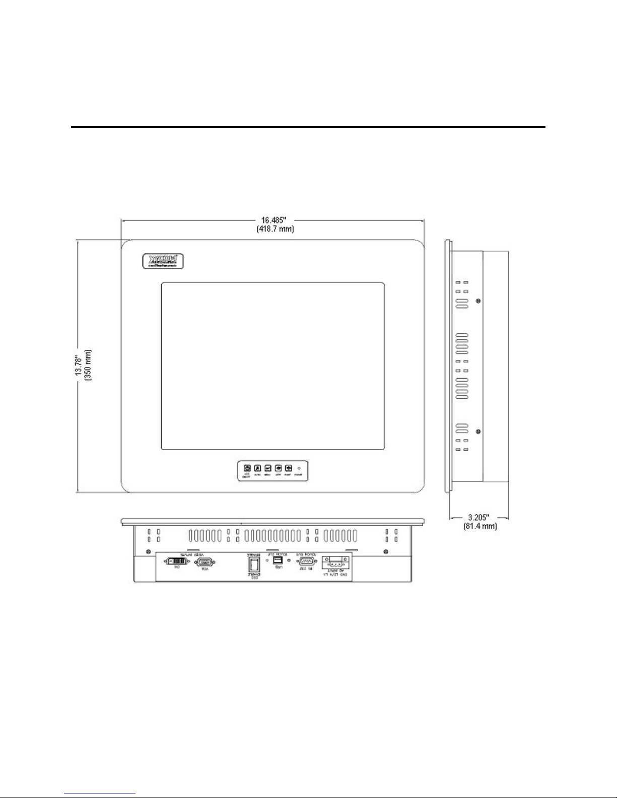
5015SLR Dimensions (Black Bezel) ......................................................................................................................3
5015SLR Dimensions (Stainless Steel Bezel) .......................................................................................................4
Front Panel Controls ..............................................................................................................................................5
Rear Panel Controls...............................................................................................................................................5
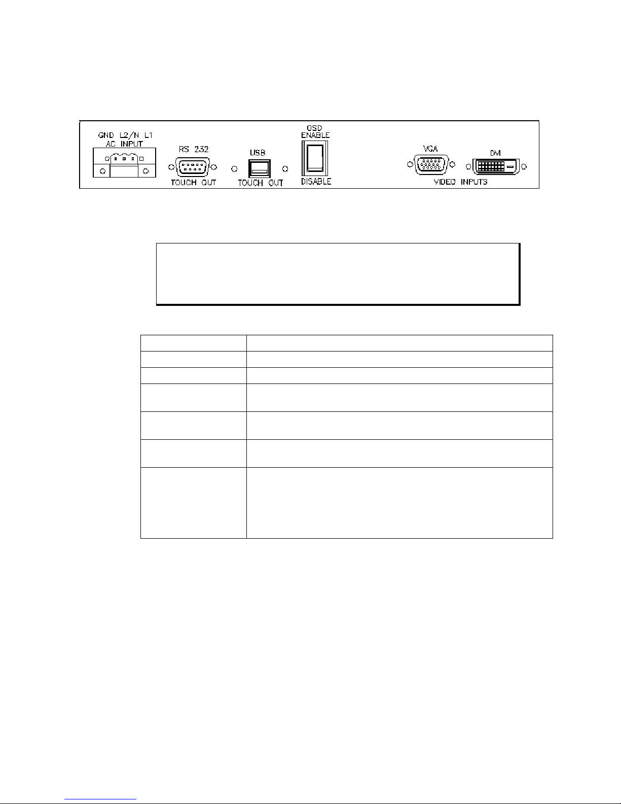
I/O Panel ................................................................................................................................................................6
LOCATION AND ENCLOSURE CONSIDERATIONS .................................................................................................................7
PANEL INSTALLATION.....................................................................................................................................................8
POWER MANAGEMENT.................................................................................................................................................11
System Power......................................................................................................................................................11
Excessive Heat ....................................................................................................................................................13
Electrical Noise ....................................................................................................................................................13
Line Voltage Variation ..........................................................................................................................................14
HAZARDOUS LOCATIONS INSTALLATIONS .......................................................................................................................14
Definitions ............................................................................................................................................................16
Power Switch .......................................................................................................................................................18
Cable Connections...............................................................................................................................................18
Operation and Maintenance.................................................................................................................................19
Safety Agency Approval.......................................................................................................................................19
CHAPTER 3 – MONITOR SETTINGS .........................................................................................................................20
ON-SCREEN DISPLAY (OSD) SWITCH ..........................................................................................................................20
MODE AND IMAGE ADJUSTMENT ...................................................................................................................................20
Recall the Factory Default Settings......................................................................................................................23
ANALOG RGB INTERFACE SPECIFICATIONS ...................................................................................................................23
VIDEO MODES ............................................................................................................................................................24
CHAPTER 4 – OPERATOR INPUT.............................................................................................................................25
INSTALLING THE TOUCH SCREEN DRIVER ......................................................................................................................25
CALIBRATING THE TOUCH SCREEN................................................................................................................................26
ACCESSING THE “MOUSE RIGHT BUTTON” FUNCTIONALITY WITH THE TOUCH SCREEN .......................................................26
USING A POINTING DEVICE WITH A TOUCH SCREEN FOR DOS .........................................................................................26
CHAPTER 5 – HARDWARE........................................................................................................................................27
VGA INPUT CONNECTOR.............................................................................................................................................27
DVI-D INPUT CONNECTOR ..........................................................................................................................................28
SERIAL INTERFACE ......................................................................................................................................................28
Touch Screen RS-232 Output Connector ............................................................................................................29
TOUCH SCREEN USB OUTPUT CONNECTOR .................................................................................................................29
HARDWARE SPECIFICATIONS........................................................................................................................................30
ENVIRONMENTAL SPECIFICATIONS ................................................................................................................................31
BEFORE CONTACTING TECHNICAL SUPPORT..................................................................................................................32
CONTACTING TECHNICAL SUPPORT ..............................................................................................................................32
PRODUCT REPAIR PROGRAM / RETURNING A UNIT TO PRO-FACE.....................................................................................33

1144812(D)
Chapter 1 – Introduction
Product Overview
Pro-face/Xycom industrial flat panel touch monitors offer state-of-the-art
performance and features while meeting the rigorous requirements of the plant floor.
Pro-face/Xycom’s 5015SLR sunlight readable, high-resolution flat panel monitor
reflects the latest technology. The 5015SLR incorporates an industrialized enclosure,
a high bright LCD display with a resistive touch screen containing integrated films
that attenuate UV light and allows transmission of visible light.
Standard Features
• 15” Flat Panel TFT XGA supporting resolutions up to 1024x768
• 3.025” mounting depth
• Five-wire analog resistive touch screen with both RS-232 and USB interfaces
• Front panel controls for on-screen menus with lock-out switch on rear of units (for
units with aluminum bezel)
• DVI-D and 15-pin analog video inputs
• NEMA 4, 4X and 12 front panel (when properly mounted)
Optional Features
• Stainless steel front bezel, with rear panel controls for on-screen menus and lock-out
switch
• 24V DC input power (optional)
Caution
Leaving your TFT LCD display on constantly can result in temporary image
retention (TIR). TIR can be avoided by using a screen saver, enabling the
idle/doze timeout feature, or by turning off the display when it is not in use.

5015SLR Flat Panel Industrial Touch Monitor Chapter 1 - Introduction
2144812(D)
Unpacking the Unit
When you remove the 5015SLR from its shipping box, verify that you have the parts
listed below. Save the box and inner wrapping in case you need to reship the unit.
• 5015SLR unit
• Installation Mounting Clip Fastners (14)
• VGA cable, 10 ft. (3 m), and
• RS-232C Cable, 10 ft. (3 m) for RS-232C touch option, and
• USB Cable, 10 ft. (3 m) for USB touch option
• Documentation and Support Library CD-ROM, which contains this manual and all
drivers required by this unit.
Quick Startup
This section depicts the steps to get the system up and running without explaining the
capabilities and options.
Warning
Remove power from the unit and disconnect the power cord before making
any adjustments to the inside or outside of the monitor.
Warning
For Hazardous Locations installation, review Hazardous Locations
Installation in Chapter 2 before startup.
To prepare the system for use, perform the following steps.
1. Attach the appropriate touch cable (USB or RS-232), following the instructions
in Chapter 2.
2. Attach the VGA cable.
3. Attach the power cord from the power receptacle to a properly grounded 100-240
V AC, 50-60 Hz, or an optional 18-30 V DC power source. (See System Power in
Chapter 2 for more information.)
4. First, turn on power to the 5015SLR (via an outlet power switch if applicable).
Then turn on power to the host computer. The system will boot up into the
operating system.
5. If using touch feature, install drivers on the host computer via the floppy, the CD-
ROM, or the network, as applicable.

3144812(D)
Chapter 2 – Installation
Product Dimensions
5015SLR Dimensions (Black Bezel)
Figure 2-1. 5015SLR Dimensions

5015SLR Flat Panel Industrial Touch Monitor Chapter 2 – Installation
4144812(D)
5015SLR Dimensions (Stainless Steel Bezel)
Figure 2-2. Stainless Steel 5015SLR Dimensions

5015SLR Flat Panel Industrial Touch Monitor Chapter 2 – Installation
5144812(D)
Front Panel Controls
Figure 2-3. 5015SLR Front Panel Controls
Rear Panel Controls
Figure 2-4. Stainless Steel 5015SLR Rear Panel Controls
Table 2-1. 5015SLR Front and Rear Panel Controls Functions
LCD ON/OFF
Power On/Off1
POWER (LED) Power Indicator
On = Power On, Off = Power Off
2 AUTO Automatically optimize positions, phase & clock when OSD is not
shown. Exit the OSD menu when OSD is shown
3 MENU Enter OSD
Access sub-menu & selection
4 LEFT Selection or adjustment when OSD is shown
Quick Volume adjustment (Unused)
5 RIGHT Adjustment when OSD is shown
Quick Volume adjustment (Unused)

5015SLR Flat Panel Industrial Touch Monitor Chapter 2 – Installation
6144812(D)
I/O Panel
Figure 2-5. 5015SLR I/O Panel
Warning
To maintain a safe condition, do not use the USB port when the unit is
operating in the presence of a hazardous environment.
Table 2-2. 5015SLR I/O Panel Functions
Feature Description
AC Input 100-240 VAC auto-ranging (AC units only)
DC Input 19-30 VDC (DC units only)
Touch output to
computer
The two following features will be available on all units.
Touch Out USB and
RS232
USB and RS232 touch screen output
OSD Selector Switch Used to enable or disable (lock) adjustment buttons on front of
monitor
Video Inputs The 5015SLR monitor has two video input options:
Digital Video Input (DVI), a DVI-D connector, for digital signal
input to an analog monitor;
VGA Input (VGA), to connect this VGA monitor for standard
analog input from a computer.

5015SLR Flat Panel Industrial Touch Monitor Chapter 2 – Installation
7144812(D)
Location and Enclosure Considerations
• Account for the unit dimensions and operational thermal environment when selecting
an installation location or enclosure (see page 3, 11, and 28 for unit dimensions and
thermal specifications).
• You can maintain the NEMA 4 seal by mounting the unit in an approved enclosure
that has a 14-gauge (0.075"/1.9 mm thick) steel or (0.125"/3.2 mm thick) aluminum
front face.
• Place the unit at a comfortable working level.
• Mount the unit in an upright position, if possible.
• Consider locations of accessories such as AC power outlets and lighting (interior
lighting and windows) for installation and maintenance convenience.
• Prevent condensation by installing a thermostat-controlled heater or air conditioner.
• Avoid obstructing the airflow to allow for maximum cooling.
• Place any fans or blowers close to the heat-generating devices. If using a fan, make
sure that outside air is not brought inside the enclosure unless a fabric or other
reliable filter is used. This filtration prevents conductive particles or other harmful
contaminants from entering the enclosure.
• Do not select a location near equipment that generates excessive electromagnetic
interference (EMI) or radio frequency interface (RFI) (equipment such as high-power
welding machines, induction heating equipment, and large motor starters).
• Do not place incoming power line devices (such as isolation or constant voltage
transformers, local power disconnects, and surge suppressers) near the system. The
proper location of incoming line devices keeps power wire runs as short as possible
and minimizes electrical noise transmitted to the unit.
• Make sure the location does not exceed the unit's shock, vibration, and temperature
specifications (see Environmental Specifications on page 26).
• Install the unit so it does not cause a hazard from uneven mechanical loading.
• Incorporate a readily accessible disconnect device in the fixed wiring on permanently
connected equipment.
• Avoid overloading the supply circuit.

5015SLR Flat Panel Industrial Touch Monitor Chapter 2 – Installation
8144812(D)
Panel Installation
This monitor should be mounted and used where NEMA 4 and NEMA 12 type
enclosures are employed. When mounted properly, the monitor meets or exceeds the
sealing requirements set forth in the NEMA 4 and NEMA 12 specifications (per
NEMA 250). The monitor uses "U"-shaped clips and a special gasket to achieve the
proper seal.
Make a cutout in one of the walls of your NEMA enclosure (see Figure 2-6 for cutout
dimensions). Enclosures made of heavier gauge metal work better in that they won't
deform or bend as easily when the monitor's sealing gasket is compressed.
Figure 2-6. 5015SLR Cutout Dimensions

5015SLR Flat Panel Industrial Touch Monitor Chapter 2 – Installation
9144812(D)
Figure 2-7. Black Bezel Mounting Clip Locations

5015SLR Flat Panel Industrial Touch Monitor Chapter 2 – Installation
10 144812(D)
Figure 2-8. Stainless Steel Mounting Clip Locations
Mounting into a 5015SLR Opening
The 5015SLR has 14 total mounting clips: 4 on both the top and bottom of the monitor, and 3
mounting clips on both of the sides. Hold the monitor in place while you install the mounting clips
(see Figure 2-7 or Figure 2-8 for mounting clip locations). Tighten the clips in a crisscross pattern.
This will help to develop an even pressure on the sealing gasket. Tighten the clips until the back of
the monitor's front bezel begins to contact the front of the NEMA enclosure (at least 7 in-lbs of
torque).
Insert the hook section into the slots and tighten the fastener with a screwdriver, as shown. Tighten
the clips until the back of the monitor’s front bezel begins to contact the front of the NEMA enclosure
(at least 7 in-lbs of torque).

5015SLR Flat Panel Industrial Touch Monitor Chapter 2 – Installation
11 144812(D)
Figure 2-9. Fastening the Monitor to the Panel
Caution
Over-tightening the clips can cause damage to the monitor, which can result
in loss of seal integrity.
Power Management
The monitor is based on the VESA DPMS and the DVI DMPM standards. To
activate the monitor's Power Management function, both the video card and the
computer must conform to the VESA DPMS standard and the DVI DMPM standard.
System Power
It is a good practice to use isolation transformers on the incoming AC power line to
the system. An isolation transformer is especially desirable in cases in which heavy
equipment is likely to introduce noise onto the AC line. The isolation transformer can
also serve as a step-down transformer to reduce the incoming line voltage to a desired
level. The transformer should have a sufficient power rating (units of volt-amperes)
to supply the load adequately.
Proper grounding is essential to all safe electrical installations. Refer to the relevant
federal, state/provincial, and local electric codes, which provide data such as the size
and types of conductors, color codes and connections necessary for safe grounding of
electrical components. The code specifies that a grounding path must be permanent
Panel
Display
Unit
Mounting Clip

5015SLR Flat Panel Industrial Touch Monitor Chapter 2 – Installation
12 144812(D)
(no solder), continuous, and able to safely conduct the ground-fault current in the
system with minimal impedance (minimum wire required is 18 AWG, 1 mm).
Observe the following practices:
• Separate the power and ground (P. E., or Protective Earth) cable from signal cables at
the point of entry to the enclosure. To minimize the ground wire length within the
enclosure, locate the ground reference point near the point of entry for the plant
power supply.
• All electrical racks or chassis and machine elements should be Earth Grounded in
installations where high levels of electrical noise can be expected. The rack/chassis
should be grounded with a ground rod or attached to a nearby Earth structure such as
a steel support beam. Connect each different apparatus to a single Earth Ground point
in a "star" configuration with low impedance cable. Scrape away paint and other
nonconductive material from the area where a chassis makes contact with the
enclosure.

5015SLR Flat Panel Industrial Touch Monitor Chapter 2 – Installation
13 144812(D)
Power Terminal Block:
Number Function
1 AC Line Input
2 AC Neutral Input
100-240 VAC
Power Input Terminal Block
3 Protective Earth Ground
Number Function
1 + DC Line Input
2 – DC Return Input
19-30 VDC
Power Input Terminal Block
3 Protective Earth Ground
Caution:
Use AWG18 wire or greater for the 5015SLR’s power cable.
Isolate the AC main circuit line, I/O signal lines, and power cord - do not bind or group
them together.
Excessive Heat
To keep the temperature in range, the cooling air at the base of the system must not
exceed the maximum temperature specification (see Environmental Specifications on
page 28). Allocate proper spacing between internal components installed in the
enclosure. When the air temperature is higher than the specified maximum in the
enclosure, use a fan or air conditioner to lower the temperature.
Electrical Noise
Electrical noise is seldom responsible for damaging components, unless extremely
high energy or high voltage levels are present. However, noise can cause temporary
malfunctions that can result in hazardous machine operation in certain applications.
Noise may be present only at certain times, may appear at widely spread intervals, or
in some cases may exist continuously.

5015SLR Flat Panel Industrial Touch Monitor Chapter 2 – Installation
14 144812(D)
Noise commonly enters through input, output, and power supply lines and may also
be coupled through the capacitance between these lines and the noise signal carrier
lines. This usually results from the presence of high voltage or long, close-spaced
conductors. When control lines are closely spaced with lines carrying large currents,
the coupling of magnetic fields can also occur. Use shielded cables to help minimize
noise. Potential noise generators include switching components, relays, solenoids,
motors, and motor starters.
Refer to the relevant Federal, State/Provincial, and local electric codes, which
provide data such as the size and types of conductors, color codes and connections
necessary for safe grounding of electrical components. It is recommended that high-
and low-voltage cabling be separated and dressed apart. In particular, AC cables and
switch wiring should not be in the same conduit with all communication cables.
Line Voltage Variation
The power supply section of the unit is built to sustain the specified line fluctuations
and still allow the system to function in its operating margin. As long as the incoming
voltage is adequate, the power supply provides all the logic voltages necessary to
support the monitor unit.
Unusual AC line variations may cause undesirable system shutdowns. As a first step
to reduce line variations, correct any possible feed problems in the distribution
system. If this correction does not solve the problem, use a constant voltage
transformer. The constant voltage transformer stabilizes the input voltage to the
systems by compensating for voltage changes at the primary in order to maintain a
steady voltage at the secondary. When using a constant voltage transformer, check
that the power rating is sufficient to supply the unit.
Hazardous Locations Installations
Pro-face designed this system with the intention of meeting the requirements of Class
I, Division 2 and Class II, Division 2 Hazardous Locations applications. Division 2
locations are those locations that are normally non-hazardous, but potentially
hazardous should an accident expose the area to flammable vapors, gases or
combustible dusts.
These systems are non-incendiary devices. They are not intrinsically safe and should
never be operated within a Division 1 (normally hazardous) location when installed as
described here. Nor should any peripheral interface device attached to these systems be
located within Division 1 locations unless approved and/or certified diode barriers are
placed in series with each individual signal and DC power line. Any such installations
are beyond the bounds of Pro-face design intent. Pro-face accepts no responsibility for
installations of this equipment or any devices attached to this equipment in Division 1
locations.

5015SLR Flat Panel Industrial Touch Monitor Chapter 2 – Installation
15 144812(D)
It is the responsibility of the customer to ensure that the product is properly rated for
the location. If the intended location does not presently have a Class, Division, and
Group rating, then users should consult the appropriate authorities having jurisdiction
in order to determine the correct rating for that Hazardous Location.
In accordance with Federal, State/Provincial, and Local regulations, all hazardous
location installations should be inspected by the appropriate authority having
jurisdiction prior to use. Only technically qualified personnel should install, service,
and inspect these systems.
Warning
Suitable for use in Class I, Division 2 Groups A, B, C, and D, and Class II,
Division 2, Groups F and G hazardous locations or non-hazardous locations
only.Temperature Code T6.
Warning - Explosion Hazard
Substitution of components may impair suitability for Class I, Class II,
Division 2.
Advertissement Risque D’ Explosion
La substitution de composants peut rendre ce materiel inacceptable pour les
emplamements de classe I, II, Division 2.
Warning - Explosion Hazard
Do not disconnect equipment unless the power has been switched off or the
area is known to be non-hazardous.
Advertissement Risque D’ Explosion
Avant de deconnecter l’equipment, coupler le courant ou s’assurer que
l’emplacement est designe non dangereux.
Warning - Explosion Hazard
When in hazardous locations, turn off power before replacing or wiring
modules.
Advertissement Risque D’ Explosion
Dans les situations hasardees, couper la courant avant de remplacer ou de
cabler les modules.

16 144812(D)
Definitions
The following Class and Division explanations are derived from Article 500
(Sections 5 and 6) of the United States National Fire Protection Agency National
Electric Code (NFPA 70). They are not complete and are included here only for a
general description for those not familiar with generic hazardous locations’
requirements.
Persons responsible for the installation of this equipment in Hazardous Locations are
responsible for ensuring that all relevant codes and regulations related to location
rating, enclosure, and wiring are met.
Class I Locations
Class I locations are those in which flammable gases or vapors are or may be present
in the air in quantities sufficient to produce explosive or ignitable mixtures.
Class II Locations
Class II locations are those that are, or may become, hazardous because of the
presence of combustible dust.
Division 1 Locations
A Division 1 location is one in which flammable or ignitable gasses, vapors, or
combustible dusts and particles can exist due the following conditions:
•
••
•
Normal operating conditions.
•
••
•
Because of repair, maintenance conditions, leakage, or where mechanical failure
or abnormal operation of machinery or equipment might release or cause
explosive or ignitable mixtures to be released or produced.
•
••
•
Combustible dusts of an electrically conductive nature may be present in
hazardous quantities.
Note
Pro-face/Xycom 5015SLR systems are not suitable for installation within
Division 1 locations.
Note
Electrical equipment cannot be installed in Division 1 locations unless they
are intrinsically safe, installed inside approved explosion-proof enclosures, or
installed inside approved purged and pressurized enclosures.

5015SLR Flat Panel Industrial Touch Monitor Chapter 2 – Installation
17 144812(D)
Division 2 Locations
•
••
•
Class I volatile flammable liquids or flammable gasses are handled, processed,
or used, but confined within closed containers or closed systems from which
they can escape only in cases of accidental rupture or breakdown of such
enclosures or systems, or in case of abnormal operation of equipment.
•
••
•
Ignitable concentrations of Class I vapors or gasses are normally prevented by
positive mechanical ventilation, but which may become hazardous due to
mechanical failure of those ventilation systems.
•
••
•
Location is adjacent to a Division 1 location.
•
••
•
Class II combustible dust is not normally in the air in quantities sufficient to
produce explosive or ignitable mixtures. Dust accumulations are normally
insufficient to interfere with normal operation of electrical equipment or other
apparatus. Combustible dust may be in suspension in the air as a result of the
following: infrequent malfunctioning of handling or processing equipment;
combustible dust accumulations on, or in the vicinity of electrical equipment;
may be ignitable by abnormal operation or failure of electrical equipment.
Groups
All electrical equipment that is approved for use in hazardous locations must include
a group rating. Various flammable and combustible substances are divided into these
groups as a function of their individual maximum experimental safe gap (MESG),
explosion pressure, and ignition temperature.
Component temperatures and the potential for spark based upon voltage, current, and
circuit characteristics, within electrical equipment, will determine what the
equipment group rating will be. A device approved for installation within Class I,
Group A locations may also be used in Groups B, C, or D.
Table of contents
Popular Touchscreen manuals by other brands

DSC
DSC HS2TCHP E user manual

Elo TouchSystems
Elo TouchSystems ET1724L-7SWR-1-NL, ET1724L-8SW user guide

Faytech
Faytech TOUCHSCREEN-PC SERIES user guide

Panasonic
Panasonic AV-HS60C3G operating instructions

IBT Technologies
IBT Technologies IBT-3601 manual

Crestron
Crestron TPMC-V12 & TPMC-V15 operating guide