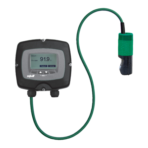
Xylem MJK pHix Compact V3 User manual

Manual
EN 4.10 Version 2103
pHix® Compact V3.
NG (NEXT GENERATION)

pHix® Compact V3. NG (next generation)
EN 4.10 Version 2103
2
Your notes:

pHix® Compact V3. NG (next generation)
EN 4.10 Version 2103
3
Table of Contents
Declaration of conformity ..........................................................................................................6
Introduction.................................................................................................................................7
Measurements and standards used .....................................................................................7
Safety instructions...................................................................................................................7
Repair .................................................................................................................................. 8
Explosion hazardous areas............................................................................................... 8
Construction............................................................................................................................8
Product identification.............................................................................................................8
Mounting ...................................................................................................................................10
Electrode types .................................................................................................................... 10
Mounting the electrode...................................................................................................... 10
Gasket and O-ring ........................................................................................................... 11
Mechanical mounting.......................................................................................................... 12
Open and closed systems .............................................................................................. 13
Mounting in open channels and reservoirs..................................................................14
Mounting in closed systems...........................................................................................16
Mounting on pipe socket................................................................................................ 17
Eletrical mounting................................................................................................................ 19
Signal cable ...................................................................................................................... 19
Cutting the signal cable..................................................................................................20
Extending the signal cable ............................................................................................. 20
Connection examples ......................................................................................................... 21
Local display..................................................................................................................... 21
Connection to PLC_PLS ..................................................................................................22
Buffer adjustment .....................................................................................................................23
Buffer adjustment details.................................................................................................... 23
Buffer solutions .................................................................................................................... 24
Cleaning................................................................................................................................ 25
Buffer adjustment using the switch ring ........................................................................... 26
Example of buffer adjustment in pH 4 and 7 ............................................................... 27
Buffer adjustment using the tilt switch.............................................................................. 28
Buffer adjustment using pHix Link..................................................................................... 29
Maintenance..............................................................................................................................30
Intervals................................................................................................................................. 30
Redox electrodes................................................................................................................. 30
Cleaning of the electrode................................................................................................... 31
Electrode lifetime................................................................................................................. 31
Electrode spare parts .......................................................................................................... 31
Electrode storage ................................................................................................................ 32
Specifications ....................................................................................................................... 32
Dimensions........................................................................................................................... 34
pHix Link software.....................................................................................................................35
Programming connection................................................................................................... 35

pHix® Compact V3. NG (next generation)
EN 4.10 Version 2103
4
General information ............................................................................................................ 35
File handling..................................................................................................................... 36
Open configuration.....................................................................................................37
Save configuration.......................................................................................................40
Connection ....................................................................................................................... 41
Read from the sensor ...................................................................................................... 42
Write to the sensor .......................................................................................................... 42
Toggle ............................................................................................................................... 43
Device settings................................................................................................................. 44
Device function ............................................................................................................50
Device setup.................................................................................................................50
Check for updates ........................................................................................................... 55
Help ................................................................................................................................... 59
Main configuration .............................................................................................................. 59
Information ....................................................................................................................... 59
Output scaling.................................................................................................................. 61
pH scaling .....................................................................................................................61
Redox scaling ...............................................................................................................64
Temperature scaling ...................................................................................................66
Buffer adjustment, pHix Link ..........................................................................................70
Temperature compensation.......................................................................................71
Buffer solution values..................................................................................................71
MJK buffer values ........................................................................................................72
Buffer supplier..............................................................................................................75
Communication ............................................................................................................... 75
Online data........................................................................................................................... 76
Information - online ......................................................................................................... 76
Output values................................................................................................................... 77
pH actual value.............................................................................................................77
mV actual value ............................................................................................................77
Temperature actual value...........................................................................................78
mA actual value............................................................................................................78
Output mode................................................................................................................79
Buffer values..................................................................................................................... 81
Status ................................................................................................................................. 82
Register list ........................................................................................................................... 83
General descriptions....................................................................................................... 83
Register list, detailed....................................................................................................... 84
Appendencies...........................................................................................................................85
Error codes ........................................................................................................................... 85
Standard transmitter configuration ................................................................................... 85
Modbus communication..................................................................................................... 86

pHix® Compact V3. NG (next generation)
EN 4.10 Version 2103
5
Contact
You can always contact your local representative or the MJK hotline for advice
and guidance:
Europe: Tel.: +45 45 56 06 56, e-mail: [email protected]
Visit our web site www.mjk.com to learn more about MJK Automation, our
other products and the people behind them.

pHix® Compact V3. NG (next generation)
EN 4.10 Version 2103
Declaration of conformity /
6
Declaration of conformity

pHix® Compact V3. NG (next generation)
EN 4.10 Version 2103
1 http://www.mjk.com
Introduction /Measurements and standards used
7
1.
2.
3.
Introduction
Thank you for choosing a pHix® Compact pH / Redox transmitter. We have
done everything possible to make a pH / Redox transmitter that can fulfill all
your demands.
pHix® Compact is very simple to install and connect, as electrode, fitting and
transmitter is built together in the sameNEMA 6X / IP 68 class enclosure. By
doing so, all error sources like e.g. bad cable connections and leaking fittings
are eliminated.
As pHix® Compact is equipped with an union flange in one end and male
thread in the other, the transmitter is very easily mounted in open tanks as well
as pipes.
You can always contact your representative or the MJK Service Hotline for
advice and guidance. Also, take a look at www.mjk.com1
pHix® Compact is registered trademark of MJK.
Measurements and standards used
This manual uses both the US standard measurement system (inches),
Fahrenheit and North American industry standards and the metric
measurement system, Celsius and European industry standards and side by
side.
Safety instructions
Read this manual carefully.
Be aware of the environment on the installation site. Wear necessary
protective equipment and follow all current safety regulations.
pHix® Compact can provide a start signal for dangerous machinery.
Always ensure that connected machinery and other equipment are
effectively being put out of service (i.e. removal of main fuses, lock main-
and/or security switches in off position) before commencing setting, fault
finding, service and maintenance work etc.

pHix® Compact V3. NG (next generation)
EN 4.10 Version 2103
Introduction /Construction
8
Repair
Repair must only made by MJK or by a service representative approved by
MJK.
Explosion hazardous areas
Note! pHix® Compact must not be installed in explosion hazardous areas!
Construction
pHix® Compact is a loop powered 4-20 mA 2-wire transmitter with power
supply and measuring signal transmitted over the same two wires.
pHix® Compact also has Modbus® communication capabilities via the seperate
RS485 wires where both the primary measuring signal (pH or redox) and the
secondary measurement signal can be read. Modbus® communication gives
the possibility to configure nearly all parameters like measuring ranges,
electrode parameters and also commands for buffer adjustment.
Modbus® communication requires that pHix® Compact is connected to a
RS485 Communication device or a PLC with RS485 interface.
pHix® Compact is delivered as standard for pH or redox (ORP) measurement
and temperature, but can also be delivered with non-standard settings.
Product identification
Check that the item(s) delivered corresponds to the ordered item(s). The item
number is printed on a label that is sticked onto the packing. Shown in the
following, is the label for a delivery including a pHix® Compact transmitter with
pH electrode with zero point at pH 4,6:

pHix® Compact V3. NG (next generation)
EN 4.10 Version 2103
Introduction /Product identification
9
1.
2.
3.
4.
Item number
Item description
Serial number
Electrode specification.
An identical marking is found on the pH transmitter cable:

pHix® Compact V3. NG (next generation)
EN 4.10 Version 2103
Mounting /Electrode types
10
Mounting
Electrode types
The electrode housing is marked with information about electrode type and
measuring range for the actual electrode:
pH electrode, item no. 160310, 1 - 14 pH, 50-176° F /10-80° C, 0 = 4.6 pH.
pH electrode, item no. 160311, 1 - 14 pH, 50-176° F /10-80° C, 0 = 7.0 pH.
Redox electrode, item no. 160312, 176° F /0-80° C.
Mounting the electrode
Upon delivery of pHix® Compact, the electrode is not mounted.pHix®
Compact is configured for the electrode type included in the delivery, and
therefore it must only be used together with the electrode with which it was
delivered.

pHix® Compact V3. NG (next generation)
EN 4.10 Version 2103
Mounting /Mounting the electrode
11
Contact MJK if other electrode types should be used. Replacement of an
electrode to another of the same type does not require reconfiguration.
The electrode must not become dry. Therefore, do not remove the protective
cap before before commissioning of pHix® Compact.
Gasket and O-ring
It is very important that both gasket and O-ring and packing surfaces are clean
and smooth and without cracks and scratches to avoid penetration of liquid in
the center plug connection.
Check that gasket and O-ring are complete and clean and that they are placed
correctly.
Likewise, the connectors in both transmitter and electrode should be absolutely
clean and dry. Use a dry cloth if needed.

pHix® Compact V3. NG (next generation)
EN 4.10 Version 2103
Mounting /Mechanical mounting
12
1.
2.
3.
4.
Check that the connectors are absolutely clean and dry.
Lubricate the O-ring in acid-free grease or Vaseline.
Check that the O-ring is placed correctly in the recess of the new
electrode.
Check that the hole for the electrode in the pHix® Compact is completely
dry – if necessary use a dry cloth.
Screw in the new electrode and tighten by hand. Note! Do not use tools!
5. Finally, pHix® Compact must be buffer adjusted(see page23) prior to
commissioning.
Mechanical mounting
pHix® Compact is made from Fortron (PPS) and/or stainless steel (EN 1.4404 /
AISL316L) and because of this, it has a tremendous resistance against
chemicals.pHix® Compact can, when mounted in a pipe, be used for
measuring in solvents and strong alcalic or acid liquids

pHix® Compact V3. NG (next generation)
EN 4.10 Version 2103
Mounting /Mechanical mounting
13
Open and closed systems
pHix® Compact is designed for measuring in both open and closed systems.
Open systems are, for example, gutters, wells, and reservoirs. Closed systems
are, for example, pipe systems or tanks/vessels.
THE US ALL OTHERS
pHix® Compact has class IP 68 /NEMA 6X enclosure, and therefore withstands
submersion into open system to a max. pressure of14 psi or 30 ft WG /1 bar
or 10 mWG.

pHix® Compact V3. NG (next generation)
EN 4.10 Version 2103
Mounting /Mechanical mounting
14
1.
2.
3.
4.
THE US ALL OTHERS
pHix® Compact conforms to pressure class PN 5, and can therefore be
mounted in closed systems with a working pressure ofmax. 72 psi /5 bar.
Mounting in open channels and reservoirs
Due to the lifetime of the electrode and measurement accuracy, the following
should be complied with when mounting pHix® Compact.
pHix® Compact should be mounted on a location with a good liquid
circulation.
The electrode tip should be minimum 30 cm below the liquid surface.
The electrode tip must not touch the bottom.
The cable must not be suspended in a cable bracket.

pHix® Compact V3. NG (next generation)
EN 4.10 Version 2103
Mounting /Mechanical mounting
15

pHix® Compact V3. NG (next generation)
EN 4.10 Version 2103
Mounting /Mechanical mounting
16
Mounted on a pipe end
When measuring, pHix® Compact should be firmly fixed. Fixed mounting can
be made by means of a pipe with 5/4" inner thread (ISO 228-1), and screwing
pHix® Compact directly into the pipe.
THE US ALL OTHERS
pHix® Compact mounted directly on a immersion bracket (item no. 155205),
which is fastened with universal bracket (item no. 200205) and wall bracket
(item no. 200215).
Mounting in closed systems
The electrode is filled with a liquid which should cover the membrane internally
at all times. Therefore, pHix® Compact should not be mounted in angles
exceeding 75° from vertical.

pHix® Compact V3. NG (next generation)
EN 4.10 Version 2103
Mounting /Mechanical mounting
17
1.
2.
Because of the liquid inside the electrode, pHix® Compact should always be
mounted in angles less than 75° from vertical.
pHix® Compact can be screwed into a pipe stub with 2" outer thread. This can
happen by means of an union (item no. 521409) placed over the housing
flange after removal of the switch ring.
Pull off the switch ring. Put on the union. Put on the switch ring if
needed.
The switch ring is only used for buffer adjustment (calibration), but it is also
possible to perform a buffer adjustment(see page23) without using the switch
ring.
Mounting on pipe socket
In order to ensure a tight seal and correct function of pHix® Compact, the
following should be complied with:
The pipe socket must be flushed and free of burrs, etc.
The pipe socket must have a length so that the tip of the electrode is
immersed min. 10 mm into the liquid.

pHix® Compact V3. NG (next generation)
EN 4.10 Version 2103
Mounting /Mechanical mounting
18
3.
4.
5.
Take care to have adequate room for mounting and removal of pHix®
Compact.
The working pressure of the system must not exceed72 psi /5 bar g .
The working temperature of the system must not exceed 176° F /80° C.
See also the following illustrations for correct adaptation to the pipe system.
US ONLY ALL OTHERS
Max working pressure = 72 psi /5 bar g. Max working temperature = 176°
F /80° C.
US ONLY ALL OTHERS

pHix® Compact V3. NG (next generation)
EN 4.10 Version 2103
Mounting /Eletrical mounting
19
pHix® Compact is mounted correctly when the electrode tip is emerged min.
½" in /10 mmunder the pipes inner pipe wall.
Eletrical mounting
pHix® Compact must not be installed in explosion hazardous
locations!pHix® Compact should be connected to an active 4-20 mA input or
supplied from a separate 10-28 VDC voltage source.Max power consumption
is 50 mW.
pHix® Compact 4-20 mA output(s) is galvanically separated from the liquids
potential.
Signal cable
Depending on the type, pHix® Compact comes with one or two galvanically
separated mA signal outputs and Modbus RS485.
Note! pHix® Compact is delivered with cable made of PUR.
pHix® Compact with 2 x 4-20 mA outputs, one for pH or redox measurement
and one for temperature measurement.

pHix® Compact V3. NG (next generation)
EN 4.10 Version 2103
Mounting /Eletrical mounting
20
Cutting the signal cable
The cable comes with stripped wire ends ready for mounting.
pHix® Compact uncut cable-end with one, respectively two, signal outputs.
Extending the signal cable
There are no specific demands to the cable that may be used for extending the
existing cable, except that it should be shielded and that the voltage drop
should not be too big.
Table of contents
Other Xylem Transmitter manuals
Popular Transmitter manuals by other brands

K-Mate
K-Mate AT-1500 user manual

Sensor Electronics
Sensor Electronics SEC 3100 Instruction and operation manual

E+H
E+H Cerabar T PMP 135 technical information

evertz
evertz 7700 MultiFrame manual

Microcyber
Microcyber NCS-TT106H-R1 user manual

Endress+Hauser
Endress+Hauser Cerabar S PMC71 installation instructions