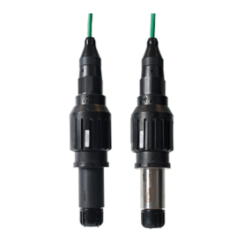
Xylem MJK SuSix User manual

1EN 5.10 SuSix Manual 2007 FW: 841013-005/843003-001
Turbidity and Suspended Solids Transmitter
Installation and User Manual
Turbidity and Suspended
Solids Transmitter

2EN 5.10 SuSix Manual 2007 FW: 841013-005/843003-001
Turbidity and Suspended Solids Transmitter
CE CERTIFICATE OF CONFORMITY
This product complies with the requirements concerning electromagnetic compatibility (EMC)
stipulated in Council directive no. 89/336/EEC of 3rd may 1989, alteret at directive no.
92/31/EEC, on the approximation of the laws of the member states relating to electromag-
netic compatibility.
CE approvals
We declare that the SuSix®transmitter and ultrasonic sensors comply with the values stipulated
in EN-61010-1 and EN 61326-1.
Ex approval
The SuSix®sensor is approved for mounting in explosive amospheres: Ex II G3.

3FW: 841013-005/843003-001
Turbidity and Suspended Solids Transmitter
EN 5.10 SuSix Manual 2007
Table of Contents
1. Introduction 7
About this Manual ...................................................8
Operating Principles .................................................10
2. Safety, Repair and Product Identification 11
Safety instructions ..................................................11
Physical Mounting ..................................................11
Repair ...........................................................11
Product Identification ................................................11
3. Sensor Installation 12
Motion in the liquid ..................................................13
Mounting / position ..................................................14
Mechanical installation of a submerged sensor............................15
Preparation........................................................15
Position of submerged sensor .........................................15
Mechanial installation of sensor in a tube (in-line) ..........................16
Mounting guidelines .................................................16
Installation / Removal using Insertion Fitting 155210 .......................20
Required Tools and Materials ..........................................20
Preparing the Insertion Fitting before welding to tube ........................20
Installation of the Sensor .............................................21
Removal of the Sensor ...............................................21
4. Sensor Calibration 23
Turbidity ...........................................................23
Suspended Solids ...................................................23
Calibration Procedures ...............................................23
Delete Calibration ...................................................28
5. Converter 29
Electrical Mounting ..................................................29
Power Supply......................................................30
Changing the Power Supply Voltage 230/115 V AC .........................31
Analogue Output ...................................................33
Digital Input .......................................................34
Converter Terminals .................................................35
Sensor and Mounting Kit / Connection Board Terminals ......................36
6. System Configuration Examples 37
Magflux®with Blind Lid and SuSix®with Display Unit .......................38
Wiring Schematic #1 ................................................39
SuSix®with Blind Lid, Magflux®with Blind Lid and a Remote Display ..........40
Wiring Schematic #2 ................................................41

4EN 5.10 SuSix Manual 2007 FW: 841013-005/843003-001
Turbidity and Suspended Solids Transmitter
7. Startup 43
Initial Checks ......................................................43
Initial Measurement. . . . . . . . . . . . . . . . . . . . . . . . . . . . . . . . . . . . . . . . . . . . . . . . . .43
Language Selection .................................................43
Display Read-out, one connected unit ...................................44
Display Read-out, several connected units ................................45
Display Keys.......................................................45
8. SuSix®Menus 47
Main Menu .........................................................47
Specify Main Screen .................................................48
Data Logger .......................................................50
Graph Display......................................................52
Password ..........................................................53
Set Sensor Name...................................................55
Converter Setup .....................................................57
Sensor Calibration ..................................................58
Averaging .........................................................59
Units ............................................................60
mA Output ........................................................61
Cleaning..........................................................62
Solid curve ........................................................63
High alarm ........................................................64
Low alarm ........................................................65
Sensor error .......................................................66
Status ...........................................................67
Factory settings ....................................................68
Service Menu - Digest ...............................................69
Service Menu - Detailed ..............................................70
Display Setup .......................................................78
Language.........................................................79
Set clock .........................................................80
Modbus ..........................................................81
Factory settings ....................................................83
Display SW version..................................................83
9. Mechanical Dimensions 85
Sensor ...........................................................85
Converter and Display Unit ............................................85
Immersion Fitting ...................................................86
Insertion Fitting.....................................................86
10. Maintenance 89
Cleaning the Sensor - Once a Month ....................................89
Cleaning the Transmitter ..............................................89

5FW: 841013-005/843003-001
Turbidity and Suspended Solids Transmitter
EN 5.10 SuSix Manual 2007
Functional Tests - Once a Year .........................................89
Electronics ........................................................89
Replacing Wipers and Gaskets - Every Two Years..........................90
Maintenance interval.................................................90
Requirements......................................................90
Required materials ..................................................90
Remove the used wiper and gasket .....................................91
Install the new gasket and wiper........................................92
Appendix A. Pop-up and Error Messages 95
Appendix B. MJK-Field Link Software 99
Important Notes! ...................................................99
A. Connect a PC to the SuSix®........................................99
B. Save Log Data .................................................101
C. Upgrade Display Firmware ........................................101
D. Upgrade Converter Firmware ......................................103
E. Install/Add Languages............................................104
Appendix C. Front Panel Cut-out Drawing 105
Appendix D. Log Files 107
Appendix E. Digital Input/Output Connections 111
Main Menu Overview 112
Converter Setup Menu Overview 114
Service Menu Overview 122
Display Configuration Menu Overview 126
Index Index-1

6EN 5.10 SuSix Manual 2007 FW: 841013-005/843003-001
Turbidity and Suspended Solids Transmitter
This page intentionally left blank.

7FW: 841013-005/843003-001
Turbidity and Suspended Solids Transmitter
EN 5.10 SuSix Manual 2007
1. Introduction
Thank you for choosing the MJK SuSix®Turbidity and Suspended Solids
Transmitter. We have done our utmost to design and manufacture a quality
transmitter that satisfies your requirements.
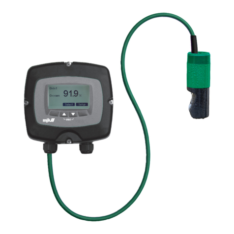
The SuSix® Transmitter, consisting of a sensor, a converter and a display,
is easy to install, calibrate and put into service. However, read this manual
first to get familiar with the SuSix®Transmitter and all its features.
The equipment must be handled and operated as instructed by the
manufacturer, MJK Automation to ensure stable operation and accurate
measurements.
The SuSix®sensor is equipped with two light-emitting diodes (LEDs,
transmitters) and four emitter diodes (receivers). The readout is based on
several measurements utilizing all the diodes to compensate for errors like
dirt adhesion, worn diodes or scratches on the lenses.
SuSix®is available in two versions – a sensor with or without a dirt wiper
and a screw thread for submerged installation in tanks or a fitting for instal-
lation in tubes. The principles for use are identical for both versions.
You can always contact your local representative or the MJK hot lines for
advice and guidance:
Visit our web sites at www.mjk.com to learn more about MJK Automation,
our other products and the people behind them.
SuSix®is a registered trademark of MJK Automation A/S, Denmark.
MJK
Blokken 9
DK-3460 Birkerød
Denmark
MJK Automation is a Xylem Brand

8EN 5.10 SuSix Manual 2007 FW: 841013-005/843003-001
Turbidity and Suspended Solids Transmitter

9FW: 841013-005/843003-001
Turbidity and Suspended Solids Transmitter
EN 5.10 SuSix Manual 2007
About this Manual
This manual is divided into a table of contents, ten chapters, five appendi-
ces, four fold-out pages and one index.
1. Introduction
Contains a presentation of the MJK SuSix®Turbidity and Suspended
Solids Transmitter, the structure of this manual and the operating princi-
ples.
2. Safety, Repair and Product Identification
Provide answers to issues regarding safety, mounting, repair,
restrictions and product identification.
3. Sensor Installation
Contains installation guidelines such as correct and wrong positioning
of the sensor in the liquid, min. and max. distances to walls and other
solid faces, and installation in tubes.
4. Sensor Calibration
Turbidity measurements require no calibration, but detailed calibration
procedures and flow charts for suspended solids calibration are avail-
able.
5. Converter
Describes the physical specifications and installation rules for the con-
verter such as power supply, in- and outputs, sensor/converter/
display configurations, etc.
6. System Configuration Examples
Illustrate how SuSix®Turbidity and Suspended Solids Transmitters can
be interconnected with for example MJK MagFlux®flow meters in real-
life scenarios.
7. Startup
Describes important checks and basic settings to get started including
the display and keyboard user interface.
8. SuSix®Menus
Contains a comprehensive description of the SuSix®menus, options
and utilities.
9. Mechanical Dimensions
Lists the SuSix®Turbidity and Suspended Solids Transmitter dimen-
sions and specifications.
10. Maintenance

10EN 5.10 SuSix Manual 2007 FW: 841013-005/843003-001
Turbidity and Suspended Solids Transmitter
Procedures for cleaning the sensor, the converter, replacing wipers and
functional test are described.
* * * * *
Appendix A. Pop-up Events / Error Messages
Lists possible pop-up messages, explains their meaning and offer
solutions to error conditions.
Appendix B. MJK-Field Link Software Upgrade
Describes in detail how to utilise the unique and intuitive MJK-Field Link
software program to upload new display and converter firmware
versions.
Appendix C. Front Panel Cut-out Drawing
A 1:1 scale drawing of the front panel outline and cut-out area for
installation and mounting purposes.
Appendix D. Log Files
An example log file illustrates the format and explains the entries.
Appendix E. Digital Input/Output Connections
Illustrates how the digital in- and outputs can be interconnected.
* * * * *
Main Menu Overview
A continuous presentation of the main menu structure
Converter Setup Menu Overview
A continuous presentation of the converter setup menu structure
Service Menu Overview
A continuous presentation of the service menu structure
Display Configuration Menu Overview
A continuous presentation of the display configuration menu structure

11 FW: 841013-005/843003-001
Turbidity and Suspended Solids Transmitter
EN 5.10 SuSix Manual 2007
Operating Principles
The SuSix® transmitter is an instrument for measuring turbidity and sus-
pended solids. The transmitter consists of a sensor, a converter and a
display unit.
Operating principles
The SuSix®sensor uses a patented 6-channel, multi-beam, pulsed infra-
red light system providing a single sensor for both turbidity and suspend-
ed solids measurement. The turbidity measurement complies with ISO
standard 7027.
The advanced optical system is combined with a patented progressive al-
gorithm using neural logic to generate a reliable high quality measurement.
All of the optical systems within the transmitter is fitted with automatic
self-diagnostics that ensure accurate measurements. The optical algorithm
compensates for errors due to fouling or aging of the optical array, and
an additional feature is a system that compensates for gas bubbles in the
sample media.
Sensor with wiper Effect of wiper
Physical fouling of the sensor head can be eliminated by an optional sen-
sor wiper system (see pictures above).

12EN 5.10 SuSix Manual 2007 FW: 841013-005/843003-001
Turbidity and Suspended Solids Transmitter
2. Safety, Repair and Product Identification
Safety instructions
• Read this manual carefully.
• Pay attention to the environment on the installation site.
• Wear necessary protective equipment and follow all current safety
regulations.
• SuSix® can invoke a start signal for dangerous machinery. Always
ensure that connected machinery and other equipment are effectively
put out of service (that is to remove the main fuses and lock main and
security switches in off-position) before commencing configuration,
fault finding, servicing, maintenance work, etc.
• WARNING: There is a risk of lethal, electrical shock from the "Mains
supply" terminals "N" and "L". Be careful not to touch these terminals
while the SuSix®is being serviced.
• WARNING: Incorrect installation or use can lead to body injury and/or
material damage!
Physical Mounting
The SuSix®converter/display unit must not be mounted in explosion
hazardous areas!
SuSix®may only be installed and commissioned by authorized MJK per-
sonnel, and all national and local regulations must be complied with.
Repair
Repair must only be made by authorized MJK personnel or by a service
representative approved by MJK.
Product Identification
A delivery will usually consist of a SuSix®sensor and a SuSix® converter
with or without a display unit.
Check that the item(s) delivered corresponds to the ordered item(s). The
part number is printed on an identification label sticked onto the converter
shipping box and on a label on the converter itself.

13 FW: 841013-005/843003-001
Turbidity and Suspended Solids Transmitter
EN 5.10 SuSix Manual 2007
3. Sensor Installation
Important!
To ensure safe and optimal functionality of the SuSix®transmitter,
the instructions below must be followed closely.
• The sensor must be mounted in a location where it is possible to per-
form a representative suspended solids measurement.
• If the suspended solids transmitter is mounted in open air, protect it
against the influence of the elements using for example a rain roof.
• Fittings and mountings must be capable of carrying the transmitter’s
weight (approx. 5 kg), and vibrations from for example pumps and
other equipment must be avoided.
• The system should be installed to facilitate access to the suspended
solids transmitter operator panel and sensor without risking personal
injury during normal operation, maintenance, cleaning of sensor, etc.
• The suspended solids transmitter must be connected to a mains outlet
that complies with national and local regulations.
• All cables must be installed, connected and mounted to minimize me-
chanical impact and electrical influence from other installations.
• The sensor cable’s maximum tensile load is adjusted to the sensor
weight.
• The sensor is a mechanical instrument. Be careful not to damage the
sensor windows. The accuracy will deteriorate, if the optics is subject
to heavy pollution, or if a steel brush is used for cleaning.
• All fuses are located on the suspended solid transmitter’s motherboard.
WARNING!
The suspended solids transmitter must not be powered until the
transmitter is correctly mounted and connected!
WARNING!
Connections to the suspended solids transmitter must not be
disconnected while the transmitter is powered.

14EN 5.10 SuSix Manual 2007 FW: 841013-005/843003-001
Turbidity and Suspended Solids Transmitter
Motion in the liquid
The liquid has to remain in motion and mixed. It is possible to achieve this
by constantly circulating the liquid, or by installing the sensor at a place
with a constant flow.
Faulty measurement due to stagnant liquid
As soon as the liquid becomes stagnant, and the suspended solids start
for sedimentation, the sensor does not recognize the suspended solids
anymore. For calibration in a sample bucket it is necessary to stir gently
the liquid, or to constantly move the sensor in order to achieve reliable
measuring results. Observe that you keep the minimum distances from the
bucket walls.

15 FW: 841013-005/843003-001
Turbidity and Suspended Solids Transmitter
EN 5.10 SuSix Manual 2007
Mounting / position
The flow direction should be parallel to the sensor surface. This prevents
turbulences at the sensor head.
Correct installation
In case of low suspended solids concentration, whirls and turbulences can
falsify the measuring result.
Incorrect installation!

16EN 5.10 SuSix Manual 2007 FW: 841013-005/843003-001
Turbidity and Suspended Solids Transmitter
Mechanical installation of a submerged sensor
Preparation
Select an easy-to-get-to position for a measuring point which can produce
a valid and representative measuring value.
Position of submerged sensor
The following three steps are of vital importance for getting optimal meas-
uring values.
1. The sensor (the optics) must be submerged at least 5 mm in the liquid.
2. The sensor to wall distance must be at least 250 mm.

17 FW: 841013-005/843003-001
Turbidity and Suspended Solids Transmitter
EN 5.10 SuSix Manual 2007
3. The distance from the sensor head (the optics) to solid faces (for exam-
ple bottom and walls) must be at least 30 - 80 mm (depending on the
liquid’s concentration).
Mechanial installation of sensor in a tube (in-line)
Mounting guidelines
1. The optical windows row have to be arranged lengthwise to the me-
dium flow direction (1).
2. Keep the minimal insertion depth >5 mm (2).
3. Control the minimum distance to the opposite wall. Must be >30 …80
mm depending on the concentration (3).

18EN 5.10 SuSix Manual 2007 FW: 841013-005/843003-001
Turbidity and Suspended Solids Transmitter
4. Make sure that the sensor is mounted within ± 45 degrees from the
horizontal plane (see below).
0
✔
✘
✔
✘
- 45 degrees
+ 45 degrees

19 FW: 841013-005/843003-001
Turbidity and Suspended Solids Transmitter
EN 5.10 SuSix Manual 2007
5. An in-line welding stud must be welded to the tube at an angle of 90
degrees in all directions (see below).
90 degrees
90 degrees

20EN 5.10 SuSix Manual 2007 FW: 841013-005/843003-001
Turbidity and Suspended Solids Transmitter
6. This drawing below illustrates a SuSix®sensor installed in an in-line
clamp fitting with parts and dimensions.
MJK Automation A/S
MJK, 206310-12 SuSix®sensor
GPA, ZFP 040-R040
PP- d40 x 1½” inner RG
1½” welding stud, 1½” outer thread RG
5 mm
1½”
nippel
122 mm
Min. Ø100 mm
Table of contents
Other Xylem Transmitter manuals
Popular Transmitter manuals by other brands

Tele Radio
Tele Radio T21-03 User instructions

Weidmüller
Weidmüller ACT20M-UI-AO-S operating instructions

CEMB
CEMB TR-NC/8 Use and maintenance instruction manual

Emerson
Emerson Rosemount 3051S Series Reference manual

HETRONIC
HETRONIC NOVA-M quick reference

Hallicrafters
Hallicrafters HT-32A Operating and service instructions