10
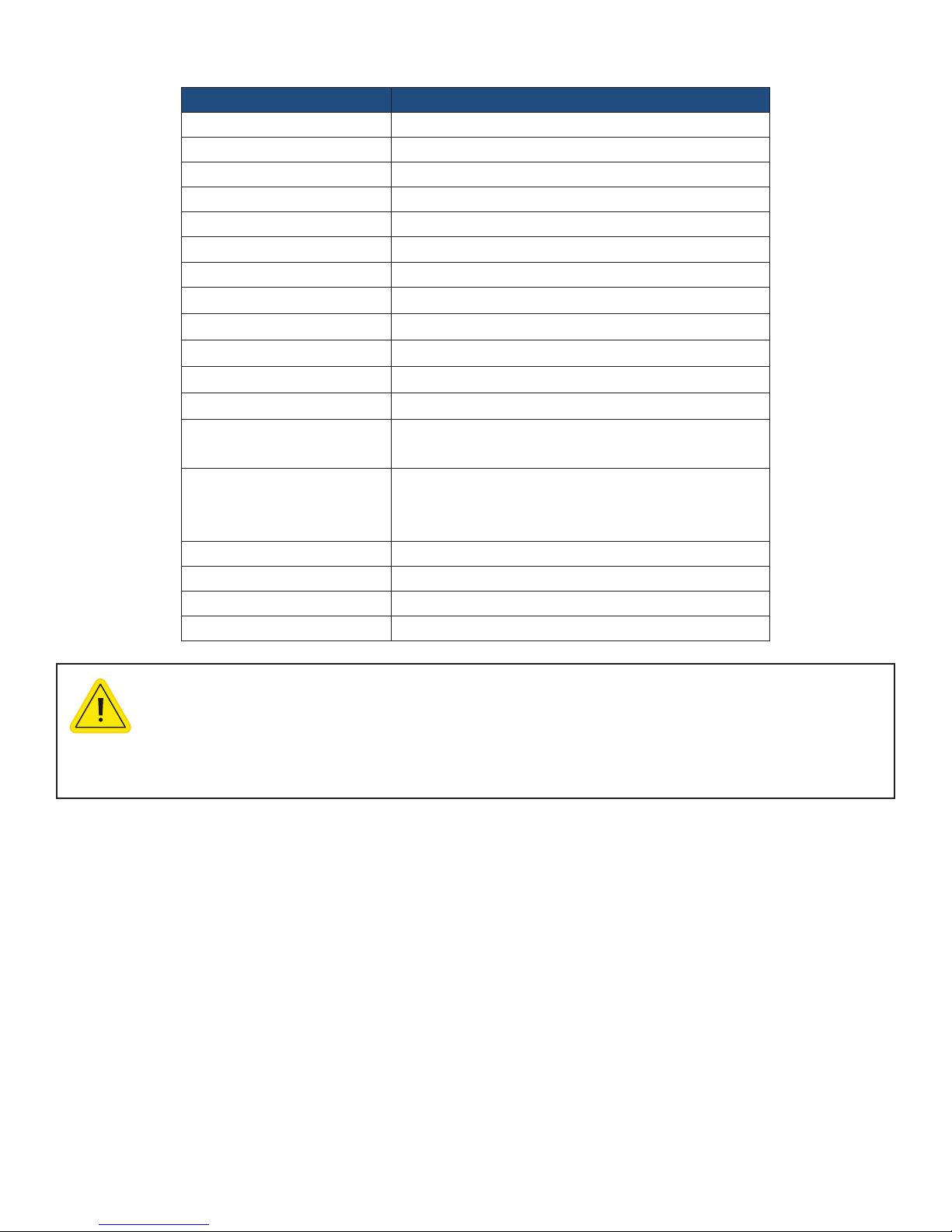
APPENDIX - SPECIFICATIONS
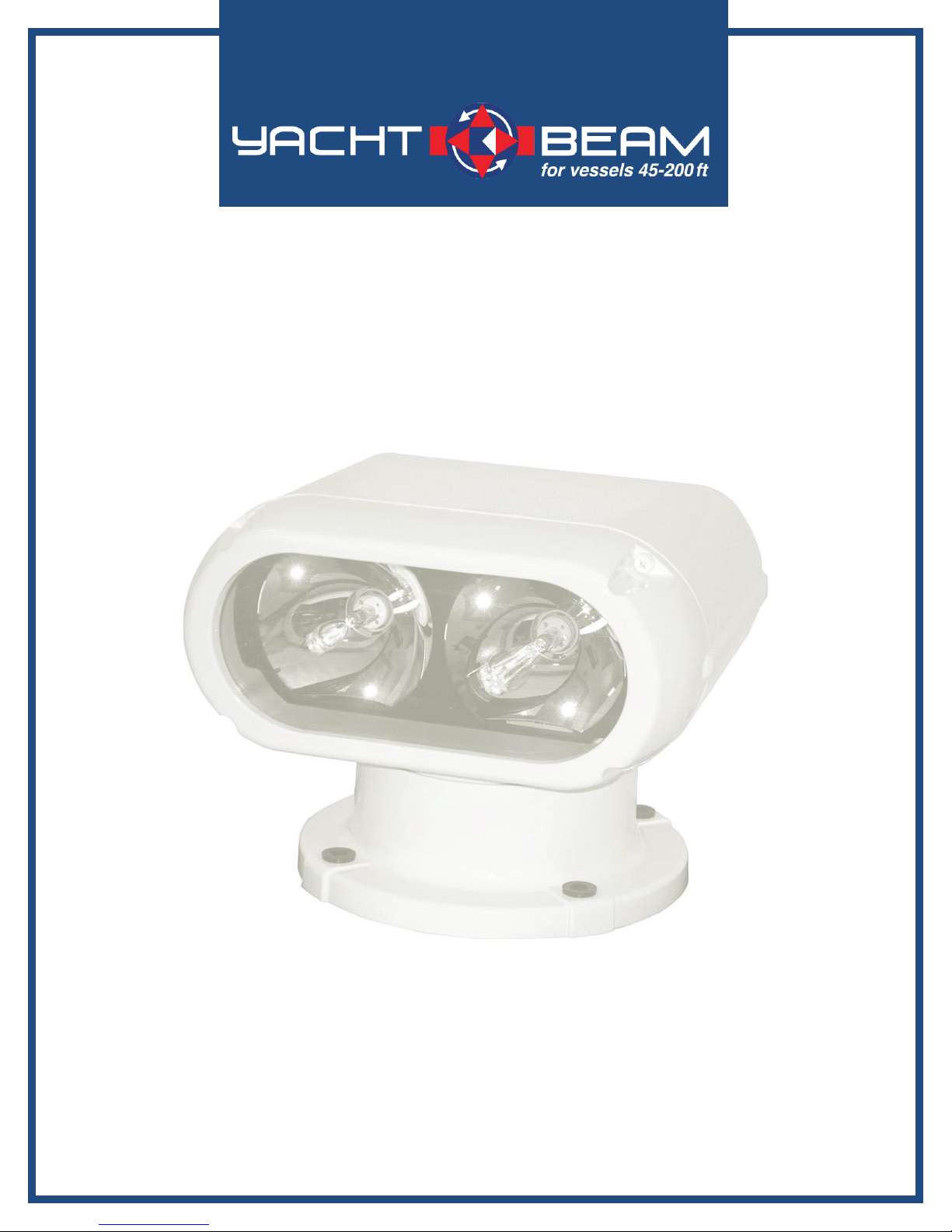
Size 12 X 13 X 9.3 in (31 X 33 X 23.5 cm)
Weight 31 lb (14.06 kg)
Material Cast aluminum, tempered glass
Input voltage* 12V- 24V
Amp draw Startup 25A @ 12V, Running 8A @ 12V
Color White
Operation Remote controlled Joystick
Beam spread 6°
Elevation angle 12° up, 38° down
Rotation 360° continuous
Rotation speed Fast 30° per second, Slow 12° per second
Elevation speed 7° per second
Lamp - Twin 35W metal halide lamps
- 1,000 hours operating life
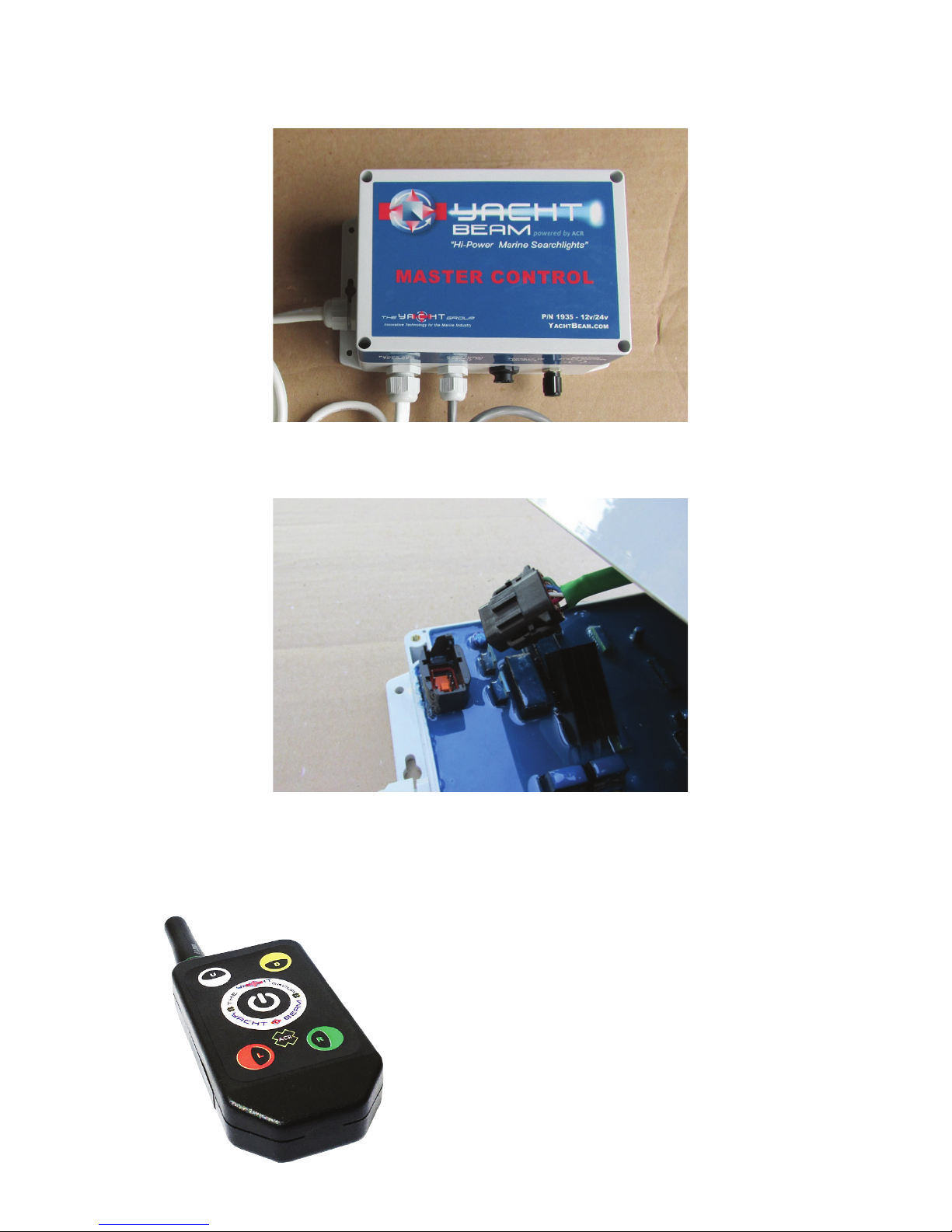
Accessories - Secondary Joystick for remote control
- Micro Wireless Remote
- Replacement 35W halide lamp (ACR P/N 6009)
Footprint diameter 9 in (23 cm)
Limited warranty 1 year
Carton dimensions 20.5 X 14.25 X 19.25 in (52.07 X 36.20 X 48.90 cm)
Carton weight 40 lb (18.14 kg)
CHARACTERISTICS SPECIFICATIONS
*CAUTION: HID light systems, when rst turned on, have a high
inrush current requirement of 25 amps. If you activate the light and the
lamps icker on and off repeatedly, check the voltage being supplied.
This condition can be experienced with voltage input of less than 11.5V.