Yaesu VX-150 User manual

VX-150 OPERATING MANUAL 1
TheVX-150 is an ultra compact FM hand-held providing up to five watts of RF power and
a wealth of new features for the 2m amateur band. The VX-150 accepts the same battery
packs, and has rubber gasket seals around all external controls and connectors keep out
dust and rain or spray, assuring years of reliable operation even in harsh environments.
Sixteen multi-function keys provide the ultimate in programmability of 199 freely tunable
memories and two VFOs. All memories store repeater shifts or separate tx/rx frequencies,
CTCSS (Continuous Tone Controlled Squelch System) tone frequencies and tone encode/
decode selections with one instant-recall call channel memory and two special purpose
memories for limited subband tuning/scanning. Busy channel band or selective memory
scanning is provided along with priority channel monitoring; 1 MHz up/down stepping;
ARS (automatic repeater shift) when tuned to repeater subbands, plus a top panel rotary
dial for memory and frequency selection. The keypad serves as a DTMF encoder during
transmission, and up to 9 DTMF memories can store 16 digits each for quick playback of
commonly used numbers.
The liquid crystal display shows seven frequency digits, memory selection, CTCSS tone
frequency while setting*, page-received status when paged by a CTCSS tone, and includes
a bargraph S/PO meter. Yaesu’s power saver system can be set by the operator for optimum
sampling/standby ratio, or can be turned off for packet operation. And our new APO (Au-
tomatic Power Off) system shuts off the transceiver to avoid dead batteries if you doze off
or are called away unexpectedly.
Operation under difficult conditions is simplified by a lamp button illuminating the display
and backlit translucent keypad, diatonically assigned function-dependent keypad beeps.
Please read this manual carefully to gain a clear understanding of the features of the VX-
150.*: Paging features require optional FVP-25.
Introduction

VX-150 OPERATING MANUAL2
Controls & Connectors
TOP PANEL
•ANTENNA Jack
This SMC jack accepts the supplied YHA-?? rub-
ber flex antenna, or any other antenna designed to
provide 50-ohm impedance on the 2m band.
‚VOL/OFF Control
This control adjusts the volume of the receiver. Turn
this control to the fully counterclockwise position
(into the click stop) to turn the transceiver OFF.
ƒDIAL Rotary Selector
This 20-position detented rotary switch tunes the
operating (or CTCSS tone) frequency or selects the memory channels, according to
which function is selected by the keys on the front panel. This knob duplicates some of
the functions of the up and down arrow keys for operating convenience.
„SQL Control
This control sets the threshold level at which received signals (or noise) open the noise
squelch. Set this control from counterclockwise just to the point where noise is si-
lenced (and the BUSY/TX indicator on the front panel is off) when the channel is
clear.
…BUSY/TX Indicator Lamp
This LED indicator glows green when the noise squelch is open during reception, and
red when transmitting.
†LCD (Liquid Crystal Display)
The display shows the selected operating conditions as indicated in the following dia-
gram:
S- and TX Power Meter Auto Power OFF Active
LOCK Feature Active
LOW Power
Alt Key Active
Memory Number
or
VFO Selection
Tone Encoder/Squelch Enabled
Digital Coded Squelch
DTMF Memory Mode
Memory Skip
BELL
Priority Channel Scanning
Repeater Shift
Memory Mode
Frequency

VX-150 OPERATING MANUAL 3
Controls & Connectors
SIDE PANELS
•PTT Button
Press and hold this (Push-to-Talk) button to transmit. The BUSY/TX indicator glows
red while transmitting.
‚Monitor (Burst) Button
In the USA version, this button opens the squelch momentarily without disturbing the
setting of the SQL control. In the European version, this button activates the 1750 Hz
Burst tone generator.
ƒLAMP Button
Press this button to illuminate the display and keypad when necessary.
…MIC/EAR Jack
This four-conductor miniature jack provides connection points for microphone audio,
earphone audio, PTT, and ground.
†EXT DC
This coaxial DC jack allows connection to an external DC power source (6.0-16V
DC).
The center pin of this jack is the Positive (+) line.

VX-150 OPERATING MANUAL4
FRONT PANELS
•Speaker
The internal speaker is located directly below the display.
‚Mic
The internal microphone is located at the bottom right-hand corner of the speaker.
ƒKeypad
These sixteen keys select the various operating features of the transceiver during re-
ception, and generate DTMF (Dual Tone Multi Frequency) tone pairs during transmis-
sion. One or two beeps will sound whenever one of the keys is pressed (if the beeper is
active). The labels on the faces of the keys indicate their primary functions, while the
labels above fifteen of the keys indicate alternate functions, which are activated by
pressing the [F/W]key first, and then another key within five seconds. When referring
to alternate key functions in this manual, we show the alternate key label followed by
the primary label in parentheses ( ). Primary key functions are referred to by the labels
on the keyfaces.
Remember to press the[F/W]key first (momentarily, unless otherwise indicated) when
you want to use an alternate key function. All key functions are described in the “Op-
eration” section, and summarized on the “VX-150 Operator’s Quick Reference Card.”
Controls & Connectors

VX-150 OPERATING MANUAL 5
ACCESSORIES SUPPLIED WITH THE VX-150
FNB-V57 7.2 V, 1100 mAh Ni-Cd Battery Pack
FC-72A/B/C/F/U Battery Chareger
Belt Clip
Hand Strap
Antenna
Operating Manual
Warranty Card
AVAILABLE OPTIONS FOR YOUR VX-150
FNB-V57 7.2 V, 1100 mAh Ni-Cd Battery Pack
FNB-62 7.2 V, 700 mAh Ni-Cd Battery Pack
FBA-25 Compact Dry Cell Battery Case for 6 AA-size cells
NC-72A 117 VAC Compact Wall Charger for FNB-14
NC-72B 220-234 VAC Compact Wall Charger for FNB-14
NC-72C 117 VAC Compact Wall Charger for FNB
NC-72U 220-234 VAC Compact Wall Charger for FNB
NC-73 Desktop Quick Charger
MH-34B4B External Hand Speaker/Microphone
MH-37A4B Earpiece/Microphone
VC-25 VOX Headset
E-DC-5B DC Cable w/Noise Filter
E-DC-6 DC Cable; plug and wire only
CSC-73 Soft Case
CN-3 BNC-to-SMA Adapter
CT-44 Microphone Adapter
YHA-?? Rubber flex antenna
Availability of accessories may vary: some accessories are supplied as standard per local
regulations and requirements, others may be unavailable in some regions. Check with your
Yaesu dealer for additions to the above list.
Accessories & Options

VX-150 OPERATING MANUAL6
ANTENNA INSTALLATION
The supplied antenna provides good results over the entire frequency range of the trans-
ceiver. However, for enhanced base station medium-wave and shortwave reception, you
may wish to connect an external (outside) antenna.
To install the supplied antenna
Hold the bottom end of the antenna, then screw it onto the
mating connector on the transceiver until it is snug. Do not
over-tighten by use of extreme force.
Notes:
¦Never transmit without having an antenna connected.
¦When installing the supplied antenna, never hold the
upper part of the antenna while screwing it onto the
mating connector on the transceiver.
¦If using an external antenna for transmission, ensure that the SWR presented to the
transceiver is 1.5:1 or lower.
BATTERY PACKS AND CASES
The following rechargeable Ni-Cd battery packs are recommended for use with the VX-
150:FNB-V57 7.2V 1100 mAh
FNB-62 7.2V 700 mAh
The following battery cases are also available for operating the VX-150with non-recharge-
able dry cell batteries (not supplied):
FBA-25 Battery Cases for 6 ‘AA’ (UM-3) batteries
The Ni-Cd packs above may be recharged either while attached to the transceiver or sepa-
rately, using the battery chargers described on the following pages. Each Ni-Cd pack should
be fully charged before it is used with the transceiver for the first time. Note that most of
these packs require different wall chargers: NC-72A/B/C/U for FNB-V57. Make certain
that you use the correct charger for each pack. The NC-73 Desktop Quick charger may be
used with all of these Ni-Cd packs.
BATTERY PACK INSTALLATION AND REMOVAL
To install the battery, hold the transceiver with your left hand, so your palm is over the
speaker and your thumb is on the top of the belt clip. Insert the battery pack into the battery
compartment on the back of the radio while tilting the Belt Clip outward, then close the
Battery Pack Latch until it locks in place with a “Click.”
Installation & Accessories

VX-150 OPERATING MANUAL 7
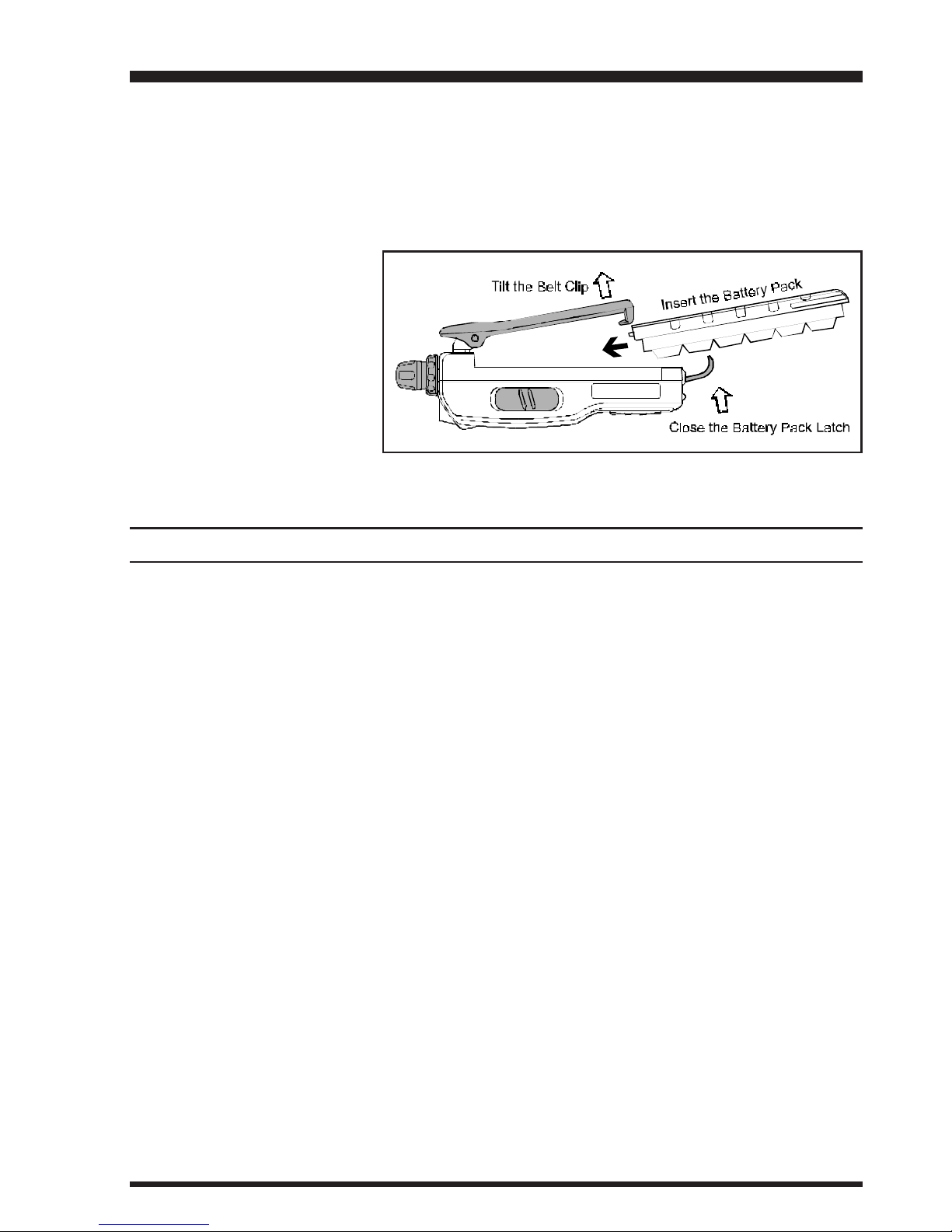
To remove the battery, turn the radio off and remove any protective cases. Open the Bat-
tery Pack latch on the bottom of the radio, then slide the battery downward and out from
the radio while unfolding the Belt Clip.
Do not attempt to open any of the rechargeable Ni-Cd packs, as they could explode if
accidentally short-circuited.
If the battery has never been
used, or its charge is de-
pleted, it may be charged by
connecting the NC-72A/B/
C/F/U Battery Charger, as
shown in the illustration, to
theEXT DC jack. If only 12
~ 16 Volt DC power is avail-
able, the optional E-DC-5B or E-DC-6 DCAdapter (with its cigarette lighter plug) may
also be used for charging the battery, as shown in the illustration.
INSTALLATION OF FBA-25 (Option)ALKALINE BATTERY CASE
The optional FBA-25 Battery Case allows receive monitoring using six “AA” size Alka-
line batteries. Alkaline batteries can also be used for transmission in an emergency, but
power output will only be 300 mW, and battery life will be shortened dramatically.
To Install Alkaline Batteries into the FBA-25
rSlide the batteries into the FBA-25 as shown in the illustration, with the Negative [–]
side of the batteries touching the spring connections inside the FBA-25.
rUnlock the bottom plate by pushing the latch in the “Open” direction.
rInstall the FBA-25 as shown in the illustration, with the [+] side facing the bottom of
the transceiver.
rRe-lock the bottom plate by carefully pressing the latch cover back into its normal
operating position.
TheFBA-25 does not provide connections for charging, since Alkaline cells cannot be re-
charged. Therefore, the NC-72A/B/C/F/U, E-DC-5B, or E-DC-6 may safely be con-
nected to the EXT DC jack when the FBA-25 is installed.
Notes:
mThe FBA-25is designed for use only with AA-type Alkaline cells.
mIf you do not use the VX-150 for a long time, remove the Alkaline batteries from the
FBA-25, as battery leakage could cause damage to the FBA-25 and/or the trans-
ceiver.
Installation & Accessories

VX-150 OPERATING MANUAL8
PRELIMINARY OPERATING INFORMATION
Before operating the transceiver for the first time, charge the battery pack completely (if
using Ni-Cd batteries) as described on pages 6and 7. If using the FBA-25 battery case,
install the batteries as described on page 7.
Connect the YHA-?? rubber flex antenna to the antenna jack on the top of the transceiver.
Never operate the transceiver without an antenna connected.
Before proceeding, please read the Controls and Connectors chapter if you have not al-
ready, to familiarize yourself with the controls. Note especially item?? on page ??, which
describes the terminology used in this chapter when referring to the keys.
Except for certain special cases mentioned later, the keypad functions as a DTMF (Dual
Tone Multi Frequency) tone generator during transmission.
SWITCHING POWER ONAND OFF
•Be sure the battery pack is installed.
‚Connect the antenna to the top panel ANTENNA
jack.
ƒSwitch on the transceiver by rotating theVOLcon-
trol clockwise out of the click-stop (a momentary
beep will sound).
If you don’t hear the two “Beep” tones when the radio comes on, the Beeper may have
been disabled via the Menu system. See page ??, which tells you how to reactivate the
Beeper.
ADJUSTING THE VOLUME LEVEL
Rotate the VOL control (immediately to the right of the Antenna) to set the desired audio
level. Clockwise rotation increases the volume level.
SQUELCH SETUP
Set the SQL control fully counterclockwise, rotate the
VOL control out of the click-stop and adjust for a com-
fortable volume on the noise or received signal. The
BUSY/TX indicator LED should glow green. If a sig-
nal is present, rotate the DIALselector on the top panel
to a channel where only noise is heard.
Adjust the SQL control just to the point where the noise is silenced and the LED is extin-
guished. If the SQL control is set further clockwise, sensitivity to weak signals will be
reduced. Now, whenever a signal reaches the receiver that is strong enough to open the
squelch, the indicator will glow green.
Operation

VX-150 OPERATING MANUAL 9
Note that while receiving, one or more bargraph segments may appear along the bottom of
the display, indicating signal strength on the receiving frequency. This indication is not
affected by the squelch setting, so even squelched signals may have some indication. If you
notice more than one or two bargraph segments appearing while the squelch is still closed,
try reducing the squelch control setting (if you want to hear weak signals).
The Monitor switch on the USA versions (just above the PTT switch) allows you to check
for channel activity beneath the squelch level and to adjust the volume without having to
adjust the squelch: just press the Monitor switch and the squelch will open.
FREQUENCY NAVIGATION
Press the [VFO(PRI)] button, if necessary, to select the VFO mode. The VX-150 has two
vfos, labelled “A” and “B” either of which can be used for all of the procedures described
in this manual. You can change vfos with the [VFO(PRI)] button at any time.
You have several ways to tune the VX-150: in selectable channel steps or 1 MHz steps
with the [s]/ [t]keys or DIAL knob, and direct keypad frequency entry.
Use the DIAL knob to tune the displayed VFO frequency at the current channel step rate.
You can also press the [s]/ [t]keys momentarily to do this, but if you press an [s]or
[t]key for more than 1/2-second scanning will start. This is described later, so for now,
just press an [s]/ [t]key again to stop (if you have to).
To change the MHz range of the VFO, you can press the [F/W]key followed by an [s]or
[t]key (or turn the DIAL knob). Note the beeps when using the [s]/ [t]keys: when
moving up, and when moving down. When done press [F/W]again, or just wait five sec-
onds.
You can also enter a frequency directly just by keying in the 1 MHz and the kHz digits. If
you are using 5 or 10 kHz steps enter five digits. Otherwise just four digits will do. Partial
entries can be cancelled with the [VFO(PRI)] key.
Examples:
To enter 146.5200 MHz, press àààà
To enter 146.5000 MHz, press ààà
Operation

VX-150 OPERATING MANUAL10
TRANSMITTING
When you wish to transmit, wait until the channel is clear (BUSY/TXlamp off), and squeeze
the PTT switch. During transmission theBUSY/TXlamp glows red, and relative transmit-
ter power output is indicated graphically along the bottom of the display. Release the PTT
switch to receive.
If using a version B (in Europe), press the T-CALL switch (above the PTT switch) to
transmit a 1750 Hz tone to access repeaters that require it.
CHANGING THE CHANNEL STEPS
Tuning steps are factory preset to 20 kHz. To change a frequency step, follow the proce-
dure below:
•Press the [F/W]key, then immediately press the [0(SET)]key to enter the Set mode.
‚Rotate the DIAL to select Menu Item #7 (“STEPSTEP
STEPSTEP
STEP”).
ƒPress the [F/W]key to enable modification of the current setting.
„Now rotate the DIAL knob to select 5, 10, 12.5, 15, 20, 25 or 50 kHz steps.
…Press the PTTkey to save the new setting and exit to normal operation.
Operation

VX-150 OPERATING MANUAL 11
KEYPAD/LCD ILLUMINATION
Your VX-150 includes a reddish illumination lamp which aids in nighttime operation. The
red illumination yields clear viewing of the display in a dark environment, with minimal
degradation of your night vision. Three options for activating the lamp are provided:
KEYKEY
KEYKEY
KEY Mode: Pressing any key causes the lamp to provide illumination for 5 seconds,
after which the lamp will automatically shut off.
5SEC5SEC
5SEC5SEC
5SEC Mode: Pressing the LAMPswitch momentarily causes the lamp to provide illu-
mination for 5 seconds, after which the lamp will automatically shut off.
TOGGLETOGGLE
TOGGLETOGGLE
TOGGLE Mode:Pressing the LAMP switch momentarily “Toggles” the lamp on and off.
The lamp will stay illuminated until you press the LAMP switch once
more.
Here is the procedure for setting up the Lamp mode:
•You first need to enter the “Set” (menu) mode. Press the [F/W]key, then immediately
press the [0(SET)]key (just below the [F/W]key) to activate the Set mode.
‚Now rotate the DIAL to select Menu Item #21 (“LMP MODELMP MODE
LMP MODELMP MODE
LMP MODE”).
ƒPress the [F/W]key to enable modification of the current setting.
„Next, rotate the DIALto select one of the three modes described above.
…When you have made your choice, press the PTT key to save the new setting for Menu
Item #21. The transceiver will now return to normal operation.
The 5SEC mode provides the greatest battery conservation, as it allows activation of the
lamp only when you press the LAMP switch.
If you press and hold in the LAMP key for one second, the lamp will remain illuminated
until you press the LAMP switch once more (no time limit).
Operation

VX-150 OPERATING MANUAL12
REPEATER OPERATION
The ARS (Automatic Repeater Shift) feature in the VX-150 provides repeater shift of the
transmit frequency whenever you are tuned to a standard repeater subband (see diagram
below). When enabled, a small “–” or “+” displayed above the upper left-hand corner of
the display that repeater shift is active, and closing the push-to-talk switch changes the
display to the (shifted) transmit frequency.
Automatic Repeater Shift (ARS)
The VX-150 provides a convenient Automatic Repeater Shift feature, which causes the
appropriate repeater shift to be automatically applied whenever you tune into the desig-
nated repeater sub-bands in your country. These sub-bands are shown below.
If the ARS feature does not appear to be working, you may have accidentally disabled it.
To re-enable ARS:
•Press the [F/W]key, then immediately press the [0(SET)] key to enter the Set mode.
‚Rotate the DIALto select Menu Item #2 (“ARSARS
ARSARS
ARS”).
ƒPress the [F/W]key to enable modification of the current setting.
„Now rotate the DIAL to select “ON” (to enable Automatic Repeater Shift).
…Press the PTTkey to save the new setting and exit to normal operation.
Manual Repeater Shift Activation
If the ARS feature has been disabled, or if you need to set a repeater shift other than that
established by the ARS, you may set the direction of the repeater shift manually.
To do this, press the [F/W]key, then press the [4(RPT)]key. This provides a “Shortcut” to
Menu #3 (“RPTRPT
RPTRPT
RPT”). Rotate the DIAL, and you will see that the “–” or “+” icon appears at the
upper of the LCD (when no icon is present, “Simplex” operation - transmit and receive on
the same frequency - has been selected, and the LCD will indicate “SIMPSIMP
SIMPSIMP
SIMP” in this case).
When the desired shift direction has been selected, press the PTT key momentarily to save
your new setting and exit.
Advanced Operation

VX-150 OPERATING MANUAL 13
Changing the Default Repeater Shifts
If you travel to a different country, you may need to change the default repeater shift so as
to ensure compatibility with local operating requirements.
To do this, follow the procedure below:
•Press the [F/W]key, then immediately press the [0(SET)]key to enter the Set mode.
‚Rotate the DIALto select Menu Item #3 (“RPTRPT
RPTRPT
RPT”).
ƒPress the [F/W]key to enable modification of the current setting.
„Now rotate the DIAL knob to select the new repeater shift magnitude.
…Press the PTT key momentarily to save the new setting and exit.
Checking the Repeater Uplink (Input) Frequency
It often is helpful to be able to check the uplink (input) frequency of a repeater, to see if the
calling station is within direct (“Simplex”) range.
To do this, just press the [REV(HM)] key momentarily. If Menu Item #20 (“REVREV
REVREV
REV/HMHM
HMHM
HM”) has
been set to “HMHM
HMHM
HM” you may press the[F/W]key, and then [REV(HM)] key. To return to the
normal uplink/downlink frequency relationship, repeat this step.
Advanced Operation

VX-150 OPERATING MANUAL14
CTCSS OPERATION
Many repeater systems require that a very-low-frequency audio tone be superimposed on
your FM carrier in order to activate the repeater. This helps prevent false activation of the
repeater by radar or spurious signals from other transmitters. This tone system, called
“CTCSS” (Continuous Tone Coded Squelch System), is included in your VX-150, and is
very easy to activate.
CTCSS setup involves two actions: setting the Tone Frequency and then setting of the
Tone Mode. These actions are set up by using the [1(SQ TYP)]and [2(CODE)]keys, or
Menu Items #25 and #26.
•Press the [F/W]key, then immediately press the [1(SQ TYP)] key. This provides a
“Short-cut” to Menu #25 (“SQL TYPSQL TYP
SQL TYPSQL TYP
SQL TYP”).
‚Rotate theDIAL so that “TT
TT
T” appears on the display; this activates the CTCSS Encoder,
which allows repeater access.
ƒYou may notice an additional “DCSDCS
DCSDCS
DCS” icon appearing while you rotate the DIAL in this
step. We’ll discuss the Digital Code Squelch system shortly.
„Rotation of theDIAL in step‚above will occasionally cause “SQSQ
SQSQ
SQ” to appear adjacent
to the “TT
TT
T” icon. When “TONE SQLTONE SQL
TONE SQLTONE SQL
TONE SQL” appears, this means that the Tone SQuelch system
is active, which mutes your VX-150’s receiver until it receives a call from another
radio sending out a matching CTCSS tone. This can help keep your radio quiet until a
specific call is received, which may be helpful while operating in congested areas.
…When you have made your selection of the CTCSS tone mode, press the PTT.
†Press the[F/W]key, then immediately press the[2(CODE)]key. This provides a “Short-
cut” to Menu #26 (“TN SETTN SET
TN SETTN SET
TN SET”).
‡This Menu selection allows setting of the CTCSS tone frequency to be used.
ˆRotate the DIAL until the display indicates the Tone Frequency you need to be using
(ask the repeater owner/operator if you don’t know the tone frequency).
‰Press the [F/W]key to save the new settings and exit to normal operation.
CTCSS TONE F
REQ UEN CY (Hz)
67.0 69.3 71.9 74.4 77.0 79.7 82.5 85.4
88.5 91.5 94.8 97.4 100.0 103.5 107.2 110.9
114.8 118.8 123.0 127.3 131.8 136.5 141.3 146.2
151.4 156.7 162.2 167.9 173.8 179.9 186.2 192.8
203.5 210.7 218.1 225.7 233.6 241.8 250.3 -
Advanced Operation

VX-150 OPERATING MANUAL 15
DCS OPERATION
Another form of tone access control is Digital Code Squelch, or DCS. It is a newer, more
advanced tone system which generally provides more immunity from false paging than
does CTCSS. The DCS Encoder/Decoder is built into your VX-150, and operation is very
similar to that just described for CTCSS. Your repeater system may be configured for
DCS; if not, it is frequently quite useful in Simplex operation if your friend(s) use trans-
ceivers equipped with this advanced feature.
Just as in CTCSS operation, DCS requires that you set the Tone Mode to DCS and that
you select a tone code.
•Press the [F/W]key, then immediately press the [1(SQ TYP)] key. This provides a
“Short-cut” to Menu #25 (“SQL TYPSQL TYP
SQL TYPSQL TYP
SQL TYP”).
‚Rotate the DIAL until “DCSDCS
DCSDCS
DCS” appears on the display; this activates the DCS Encoder/
Decoder.
ƒWhen you have made your selection of the DCS mode, press the PTT.
„Press the[F/W]key, then immediately press the[2(CODE)] key. This provides a “Short-
cut” to Menu #26 (“TN SETTN SET
TN SETTN SET
TN SET”).
…Rotate the DIAL to select the desired DCS Code (a three-digit number). Ask the re-
peater owner/operator if you don’t know DCS Code; if you are working simplex, just
set up the DCS Code to be the same as that used by your friend(s).
†When you have made your selection, press the [F/W]key to save the new settings and
exit to normal operation.
Remember that the DCS is an Encode/Decodesystem, so your receiver will remainmuted
until a matching DCS code is received on an incoming transmission. Switch the DCS off
when you’re just tuning around the band!
Advanced Operation
DCS CODE
023 025 026 031 032 036 043 047 051 053 054 065 071 072 073 074 114 115 116
122 125 131 132 134 143 145 152 155 156 162 165 172 174 205 212 223 225 226
243 244 245 246 251 252 255 261 263 265 266 271 274 306 311 315 325 331 332
343 346 351 356 364 365 371 411 412 413 423 431 432 445 446 452 454 455 462
464 465 466 503 506 516 523 526 532 546 565 606 612 624 627 631 632 654 662
664 703 712 723 731 732 734 743 754

VX-150 OPERATING MANUAL16
TONE SEARCH SCANNING
In operating situations where you don’t know the CTCSS or DCS tone being used by
another station or stations, you can command the radio to listen to the incoming signal and
scan in search of the tone being used. Two things must be remembered in this regard:
mYou must be sure that your repeater uses the same tone type (CTCSS vs. DCS).
mSome repeaters do not pass the CTCSS tone; you may have to listen to the station(s)
transmitting on the repeater uplink (input) frequency in order to allow Tone Search
Scanning to work.
To scan for the tone in use:
•Set the radio up for either CTCSS or DCS Decoder operation (see the previous discus-
sion). In the case of CTCSS, “T SQT SQ
T SQT SQ
T SQ” will appear on the display; in the case of DCS,
“DCSDCS
DCSDCS
DCS” will appear on the display.
‚Press the [F/W]key, then immediately press the [2(CODE)] key to select the “TNTN
TNTN
TN
SETSET
SETSET
SET” Menu item (when TONE SQL is selected) or “DCS SETDCS SET
DCS SETDCS SET
DCS SET” (during DCS opera-
tion).
ƒPress and hold in the[s]or [t]key to start scanning for the incoming CTCSS or DCS
tone/code.
„When the radio detects the correct tone or code, it will halt on that tone/code, and audio
will be allowed to pass. Press the [F/W]key to lock in that tone/code, and exit to
normal operation.
If the Tone Scan feature does not detect a tone or code, it will continue to scan indefi-
nitely. When this happens, it may be that the other station is not sending any tone. You
can press the PTT switch to halt the scan at any time.
You also can press the MONI key during Tone Scanning to listen to the (muted) signal
from the other station. When you release the MONI key, Tone Scanning will resume
after about a second.
Tone Scanning works either in the VFO or Memory modes.
Advanced Operation

VX-150 OPERATING MANUAL 17
CTCSS/DCS BELL OPERATION
During CTCSS Decode or DCS operation, you may set the VX-150 up such that a ringing
“Bell” sound alerts you to the fact that a call is coming in. Here is the procedure for activat-
ing the Bell will ring in accordance with this programming.
•Set the transceiver up for CTCSS Decode (“TONE SQL” or DCS operation, as de-
scribed previously.
‚Adjust the operating frequency to the desired channel.
ƒPress the [F/W]key, then press the [0(SET)]key to activate the Set mode.
„Rotate the DIALto select Menu Item #18 (“BELLBELL
BELLBELL
BELL”).
…Press the [F/W]key to enable adjustment of the Bell ringer.
†Rotate the DIAL to set the desired number of rings of the Bell. The available choices
are 1, 3, 5, or 8 rings, REPEAT (continuous ringing), or OFF.
‡Press the PTT key momentarily to save the new setting and exit to normal operation.
When a station calls you whose transceiver is sending a CTCSS tone or DCS code which
matches that set into your Decoder, the Bell will ring in accordance to this programming.
TONE CALLING (1750 Hz)
If the repeaters in your country require a 1750-Hz burst tone for access (typically in Eu-
rope), you can set the MONI key to serve as a “TONE CALL” switch instead. To change the
configuration of this switch, we again use the Menu to help us.
•Press the [F/W]key, then press the [0(SET)] key to enter the Set mode.
‚Rotate the DIAL to select Menu Item #19 (“MONMON
MONMON
MON/TCLTCL
TCLTCL
TCL”).
ƒPress the [F/W]key to enable adjustment of this Menu item.
„Rotate the DIALto select “T.CALLT.CALL
T.CALLT.CALL
T.CALL” on the display.
…Press the PTT key to save the new setting and exit.
†To access a repeater, press and hold in theMONI key for the amount of time specified
by the repeater owner/operator. The transmitter will automatically be activated, and a
1750-Hz audio tone will be superimposed on the carrier. Once access to the repeater
has been gained, you may release the MONIkey, and use the PTT key for activating the
transmitter.
Advanced Operation

VX-150 OPERATING MANUAL18
CHANGING THE TRANSMITTER POWER LEVEL
You can select between a total of three transmitter power levels on your VX-150. The
exact power output will vary somewhat, depending on the voltage supplied to the trans-
ceiver. With the standard FNB-V57 Battery Pack, the power output levels available are:
HIGHHIGH
HIGHHIGH
HIGH: ?? W MIDMID
MIDMID
MID: ?? W LOWLOW
LOWLOW
LOW: ?? W
To change the power level:
•Press the [F/W]key, then immediately press the [3(LOW)] key.
‚Now rotate the DIAL knob to select “LOWLOW
LOWLOW
LOW”, “MIDMID
MIDMID
MID” or “HIGHHIGH
HIGHHIGH
HIGH”.
ƒPress the PTTkey to save the new setting and exit to normal operation.
TRANSMITTER TIME-OUT TIMER (TOT)
The TOT feature provides a safety switch which limits transmission to a pre-programmed
value. This will promote battery conservation by not allowing you to make excessively-
long transmissions, and in the event of a stuckPTT switch (perhaps if the radio or a Speaker/
Mic is wedged between car seats) it can prevent interference to other users as well as
battery depletion. As configured at the factory the TOT feature is set to OFF, and here is
the procedure for activating it:
•Press the [F/W]key, then press the [0(SET)] key to enter the Set mode.
‚Rotate the DIAL to select Menu Item #22 (“TOTTOT
TOTTOT
TOT”).
ƒPress the [F/W]key to enable adjustment of this Menu item.
„Rotate the DIAL to set the Time-Out Timer to the desired “Maximum TX” time (1
minute, 2.5 minutes, 5 minutes, or 10 minutes).
…Once you’ve made the selection you wish to use, press the PTT key to save the new
setting and exit to normal operation.
Since brief transmissions are the mark of a good operator, try setting up your radio’s
TOT feature for a maximum transmission time of 1 minute. This will significantly im-
prove battery life, too!
Advanced Operation

VX-150 OPERATING MANUAL 19
RECEIVE BATTERY SAVER SETUP
An important feature of the VX-150 is its Receive Battery Saver, which “puts the radio to
sleep” for a time interval, periodically “waking it up” to check for activity. If somebody is
talking on the channel, the VX-150 will remain in the “active” mode, then resume its
“sleep” cycles. This feature significantly reduces quiescent battery drain, and you may
change the amount of “sleep” time between activity checks using the Menu System:
•Press the [F/W]key, then press the [0(SET)]key to enter the Set mode.
‚Rotate the DIALto select Menu Item #9 (“RX SAVERX SAVE
RX SAVERX SAVE
RX SAVE”).
ƒPress the [F/W]key to enable adjustment of this Menu item.
„Rotate the DIAL to select the desired “Sleep” duration. The selections available are
200 ms, 300 ms, 500 ms, 1 second, and 2 seconds, or OFF. The default value is 200 ms.
…When you have made your selection, press the PTT key to save the new setting and exit
to normal operation.
When you are operating on Packet, switch the Receive Battery Saver OFF, as the sleep
cycle may “Collide” with the beginning of an incoming Packet transmission, causing
your TNC not to receive the full data burst.
When the battery saving function is working, the beginning of the companion voice
breaks off and it is sometimes possible to hear it.
TX BATTERY SAVER
TheVX-150 also includes a useful Transmit Battery Saver, which will automatically lower
the power output level when the last signal received was very strong. For example, when
you are in the immediate vicinity of a repeater station, there generally is no reason to use
the full 5? Watts of power output in order to achieve full-quieting access to the repeater.
With the Transmit Battery Saver, the automatic selection of Low Power operation con-
serves battery drain significantly.
To activate the Transmit Battery Saver:
•Press the [F/W]key, then press the [0(SET)]key to enter the Set mode.
‚Rotate the DIAL to select Menu Item #10 (“TX SAVETX SAVE
TX SAVETX SAVE
TX SAVE”).
ƒPress the [F/W]key to enable adjustment of this Menu item.
„Rotate the DIAL so as to select ON (thus activating the Transmit Battery Saver).
…When you have completed your selection, press the PTT key to save the new setting
and exit to normal operation.
Advanced Operation

VX-150 OPERATING MANUAL20
DISABLING THE BUSY/TX LED
Further battery conservation may be accomplished by disabling the BUSY/TX LED. Use
the following procedure:
•Press the [F/W]key, then press the [0(SET)] key to enter the Set mode.
‚Rotate the DIAL to select Menu Item #12 (“BSY LEDBSY LED
BSY LEDBSY LED
BSY LED”).
ƒPress the [F/W]key to enable adjustment of this Menu item.
„Rotate the DIALto set this Menu item to OFF (thus disabling the BUSY/TX LED).
…Press the PTTkey to save the new setting and exit to normal operation.
BUSY CHANNEL LOCK-OUT (BCLO)
The BCLO feature prevents the radio’s transmitter from being activated if a signal strong
enough to break through the “Noise” squelch is present. On a frequency where stations
using different CTCSS or DCS codes may be active, BCLO prevents you from disrupting
their communications accidentally (because your radio may be muted by its own Tone
Decoder). The default setting for the BCLO is OFF, and here is how to change that setting:
•Press the [F/W]key, then press the [0(SET)]key to enter the Set mode.
‚Rotate the DIAL to select Menu Item #23 (“BCLOBCLO
BCLOBCLO
BCLO”).
ƒPress the [F/W]key to enable adjustment of this Menu item.
„Rotate the DIAL to set the BCLO feature to the “ON” position.
…Press the PTTkey to save the new setting and resume normal operation.
AUTOMATIC POWER-OFF (APO)FEATURE
The APO feature helps conserve battery life by automatically turning the radio off after a
user-defined period of time within which there has been no dial or key activity. The avail-
able selections for the time before power-off are 0.5/1/3/5/8 hours, as well as APO Off.
The default condition for the APO is OFF , and here is the procedure for activating it:
•Press the [F/W]key, then press the [0(SET)]key to enter the Set mode.
‚Rotate the DIAL to select Menu Item #11 (“APOAPO
APOAPO
APO”).
ƒRotate the DIAL to select the desired time period after which the radio will automati-
cally shut down.
„Once you have made your selection, press the PTT key to save the new setting and exit
to normal operation.
CHECKING THE BATTERY VOLTAGE
The VX-150’s measure the current battery voltage.
•Press the [F/W]key, then press the [0(SET)]] key to enter the Set mode.
‚Rotate the DIAL to select Menu Item #37 (“BATTBATT
BATTBATT
BATT”).
ƒPress the [F/W]key to check the battery condition.
„To return to normal operation, press the [F/W]key, then press the PTT.
Advanced Operation
Other manuals for VX-150
3
Table of contents
Other Yaesu Transceiver manuals

Yaesu
Yaesu FT-1802M User manual

Yaesu
Yaesu FT DX 3000 User manual

Yaesu
Yaesu FT-223 Instruction Manual

Yaesu
Yaesu FT-950 Technical manual

Yaesu
Yaesu FTM-400DR User manual

Yaesu
Yaesu FT-2500M Manual

Yaesu
Yaesu FT-101 User manual

Yaesu
Yaesu FTA-450 series User manual

Yaesu
Yaesu FTDX101MP Manual

Yaesu
Yaesu FT-208R Manual