Yaesu FT-8500/mh-39 User manual

,~~"-~~
/<:.:-=:'-
/:
,I
I
\/
"/
,-~/
----.--
..
~
----
--.
--
--------------_._-----~-----
_.
__
..
:-0
:u
~.=
.,.,.,
---'---'_f.UUU
_D
....
.-
.,.
I.,
:t.ti:,.':'
-,u
_D
••••••••
:-0:
I
I
1
t
Ii
FT
-8500/MH-39
Dual Band FM
Paging Transceiver
-
.".'.
"
...
:':;'~
\
-:
~
--
.....
.....
YAESlj
QIW~~
-~
""l....
_-
U
• 0
'~~~tf:
j':

Contents
Porsonnl
Computor
Control
Oporatlon
. 55
PCC Data Protocol 56
Writing Programs 58
FTS-22 Tone
Squelch
Unit Installation . . 59
Menu
Programming
&Custom Settings .
61
Menu Organization 61
Menu Headings 62-74
Introduction
.
Specifications
Accessories
&
Options
Controls
&
Connectors
Top, Front, Rear &Side Panel Views
LCD Indications
Installation
.
Installing the MH-39 Microphone
MH·39 Key Reference Tables
Basic
Operation
....
Preliminary Steps
Mixed Receive Operation
User-Proqrarnmed
Function Keys
Repeater Operation
Advanced
Operation
Spectra-Analyzer Operation
Auto Receiver Mute
Mommy
Stomon
Recalling Memories
Home Channel Memory
Split Memory Operation
Tuning Memories
Scanning
Memory Skip Scanning
Programmed Subband Tuning & Scanning
Priority Memory Monitoring
. 1
...
3
.4
.5
5-9
10
. . 11
11
15-16
19
19
22
22
23
25
25-28
28
30
30
31
31
31
33
33
34
34-35
CTCSS Operation
CTCSS Bell Paging
DTMF Code Squelch & Paging
Trigger Paging
Paging "Answer-Back"
Paging Tx Delay
Sending DTMF Messages
CustomiZing Ringer Settings
DTMF Autodialer Operation
Composing the Ringer User-Melody
APO (Auto Power Off)
Alphanumeric Character &Symbol Charts
Power-On Settings Chart
Appendix .
Packet Radio Operation
Cross-Band Repeater Operation
Transceiver Cloning
In Case of Problems
36
36
37-40
41
41
42
43
45
46
46
46
48-49
50
. 51
51
52
53
54

c
o
'-
....
.S-
t.-
U
CI)
cu
Q
2
Searching for station activity is easy with VFO, mern-
ory and proqrammed-Hmit (sub band) scanning and
the new Spectra-Analyzer feature. Select all memo-
ries or only those you want to be scanned. Two scan
modes are now available: Busy Scan searches for
activity then pauses, while Clear Scan looks for an
inactive channel to operate on - great for urban areas
with crowded bands. Scan speed can be set to nor-
malar
slow, and when activity is found, scanning
pauses, then resume after 5-seconds, or only when
the station stops transmitting. Each band has one
priority
memory
which can be monitored every few
seconds while operating from the VFO or memories.
The
built-in
CTCSS
(Continuous
Tone-Coded
Squelch
System)
provides
39
subaudible
tones
which can be stored in each memory independently.
The
CTCSS
Bell feature can be set to ring when the
tone squelch opens.
OTMF calling and paging quietly monitor until calls
to you (or only stations in groups you select) are
received. The station's 10 code is then displayed so
you know who is calling you. With answer-back paq-
ing, the FT-8500 can even acknowledge or relay
(forward)
DTMF
paging calls when you are absent. A
fully configurable paging ringer beeps, plays a mel-
ody you compose, or plays back paging 10 codes in
CWI The Trigger Paging function switches from paq-
Ing to code squelch operation after receiving a page
by pressing the
PIT
so you can talk immediately.
The DTMF paging ringer can be disabled, or set rc
ring 1, 3, 5 or 8times, and even cycle every minute
until you respond. With the one-touch paging feature.
selecting and displaying paging codes is simplified.
DTMF text messages up to eight characters long
car
be sent to other stations. Amessage 10 of eight
characters can also be sent and displayed with the
text. Received messages are displayed and auto-
matically stored for later retrieval. A tri-mode ringer
alerts you to calls or messages by sounding apreset
or user-programmed melody, or else have the built-in
CW monitor playback the message in Morse code!
For
autopatch
operation, a 1o-mernorv, 16-digit
DTMF autodialer stores nine frequently-called nurn-
bers and one
memory
reserved for a user-pro-
grammed DTMF melody ringer for playback. The
DTMF autodial memories can also be tagged with
six-character alphanumeric names.
The Tx time-out timer (TOT) limits key-down time
and the setectable-period APO (Automatic Power
Off) timer turns off the radio after a period of inactiv-
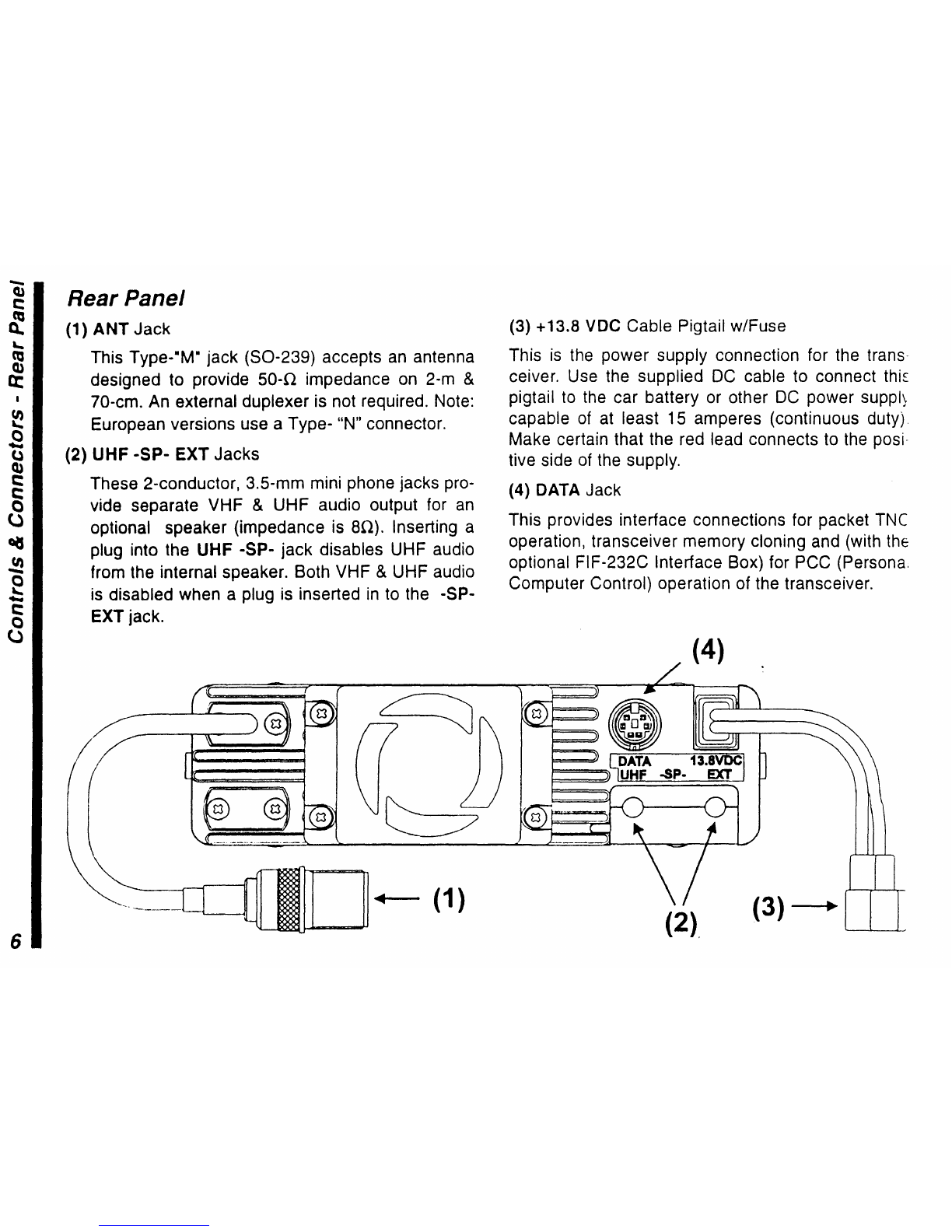
ity. A convenient rear-panel data jack is provided for
packet TNC connection. Data rate (1200/9600 BPS)
and VHF/UHF port selection can be configured via
menu programming. PCC (Personal Computer Con-
trol) and transceiver cloning is also accomplished
using this jack. Please take some time to carefuuy
review this manual thoroughly before operation.
'-'-'--.:
•.
",,!~

FT-8500 Dual-Band FM Mobile Paging Transceiver
with MH-39 DTMF Microphone
Congratulations on the purchase of your Yaesu
amateur transceiver! Whether this is your first rig, or
jf Yaesu equipment is already the backbone of your
station, rest assured that your transceiver will pro-
vide many hours of operating pleasure for years to
come. Along with the philosophy that each Yaesu
transceiver should serve you well into the future.
Yaesu stands behind our products with a worldwide
network of dealers and service centers. Feel free to
contact us if you need technical advice or assistance.
The FT-8500 is a deluxe compact FM mobile trans-
ceiver for both 2-m and lO-cm amateur band opera-
tion. A few of the new features in this dual-band rig
include the following:
• DTMF Remote Control Microphone - the MH-39
permits controlling most transceiver functions from
the palm of your hand.
•Spectra-Analyzer - view station activity above and
below a selected channel: simply turn the dial to
center a signal of interest on the scope and press
the PTT to operate! You can also view activity
among programmed memory banks. Adjustable
signal width. spacing and span markers allow fine-
tuning the spectrum view as you like.
•Configurable Memory Banks - fifty general-purpose
memories are arranged into five banks on each
band, and you can transfer memory banks from one
band to the other as needed. Free unused memo-
ries and move them where they are needed! Five
special-purpose memories (including an instant-re-
call Home channel) are also available on each
band. Memories can be tagged with an 6-character
alphanumeric name and this name can be dis-
played instead of the frequency.
• Two user-programmed function keys - makes multi-
keystroke functions as simple as the push of a
button.
• DTMF and Message Paging with CW Monitor -
decodes incoming DTMF Paging codes and mes-
sages with selectable CW playback speed.
• Dual In-Band Receive (V&V and U&U) with Auto
Receiver Muting for improved cross-band opera-
tion. Receiver muting has selectable levels and
duration.
The upper LCD shows channel data and most pro-
grammable settings, you can even display the DC
supply voltage. The lower dot matrix display shows
programming menus and also double as a Spectra-
Analyzer display for viewing channel activity. The
LCD has selectable contrast and illumination levels
for maximum visibility under varying lighting.
c
o
'-"
.....
.
s.
~
(J
CI)
(1)
Q
1

Specifications
General
Froquoncy
ranqo:
Channol
stops:
(Rx)
110-174
MHz
410-500
MHz
(Tx)
144-148
MHz
430-450
MHz
5. 10.
12.5.15.20.25
&50 kHz
Maximum
deviation:
FM Noise (@ 1kHz):
Spurious emissions:
Microphone
type:
1: 5 kHz
better than -40dB
>60 dB
below
carrier
2-kU
condenser
Operating
temp. range: -20 to
+60:
C
Case
size (WHO): 140 ;< 40 x160
wlo
knobs
Frequency
stability: 1:10 ppm from -20 to +60:; C(VHF,
:.5 ppm from -5 to
...
50'
C(UHF)
Repeater srutt: .:600 kHz .
~5
MHz (programmable)
Current
consumption:
Receive: less than 1 A
Transmit
(Max.]
(high)
(mid)
(low)
better than 70 dB
Specifications subject to change without notice or obligation.
Specifications guaranteed within
amateur
bands only.
Receiver
Squelch Sensitivity: better than 0.13
11
V
AF Output: 2W@su for 5% THO
AF Output Impedance:
4-16
n
(8-n
internal speaker)
Image
Rejection:
Circuit type: double-conversion superheterodyne
IFs: 45.05 MHz &455 kHz (VHF)
58.525 MHz &455 kHz (UHF)
12-dB SINAD Sensitivity: <0.18
~V
(main)
<0.25
~V
(sub)
Selectivity (-6/-60 dB): 12/24 kHz
UHf
9.0 A
5.0 A
4.0 A
WE
11.5 A
6.0 A
4.5 A
1. 1 kg (2.4 Ib)
F3 (G3E), F2
11.7-15.9VDC
Weight
(approx.):
Ermssion type:
Supply
voltage:
variable reactance
Transmitter
AF
output:
(high)
(mid)
(low)
Modulation
system:
YJ:iE
SOW
lOW
5W
UHf
35W
lOW
5W
Frequency ranges
and
repeatershift vary according to transceiver
version, check with
your
dealer.
3

CI)
e
Q
;:
8-
aes
CI)
.~
'-
e
CI)
CI)
cu
u
u
<C
4
Accessories &Options
Accessories
MH-39A6J
DTMF Microphone
MMB-36 Mobile Mounting Bracket
DC Power Cord w/fuse
Spare 15-A Fuse
Options
FS-10Smart Controller
YSK·8500
Separation Kit
FTS·22 Tone Squelch Unit
SP-7 External Loudspeaker
FP-800 AC Power Supply w/Loudspeaker
MMB-60 Quick-Release Mobile Bracket
AvaIlabIlity of accessories may vary. Some accessories are sup-
plied as standard
per
local requirements. others may be unavailable
In some teqion». Check with your local Yaesu dealer for changes to
the above list.

Controls
&Connectors
Front Panel
(1) LCD (Liquid Crystal Display)
The upper half of the display consists of seg-
mented digits for frequency readout and various
icons representing enabled transceiver features.
The lower half contains a dot-matrix display for
Spectra-Analyzer viewing, menu programming and
alphanumeric name display. See the graphics on
page
'0
for descriptions of the display icons and
indications.
(2) DIAL Rotary Selector
Rotate this to tune, or select memories and other
settings, according to the function selected by the
keys. This knob duplicates some functions of the
MH-39 i;J and
8/3
keys for convenience.
(3) TX Indicator
This LED indicator glows red when transmitting.
(4) Auto Dimmer Photo Sensor
This senses ambient lighting and adjusts LCD
backlighting for optimum visibility.
~
o
....
o
(1)
e
e
o
l)
~
.!!!
e
....
c
o
U
(1)
<.
I.
(3)
'"
r-----------
.............
--------
..............
-......-...-...--..,~
FT·8500
Front
Panel
(4)
(2) 5

~
c
.....
u
Q)
e
e
Q
(,)
~
~
e
.....
e
Q
U
Rear Panel
(1)
ANT
Jack
This Type--M- jack
(50-239)
accepts an antenna
designed to provide
50-11
impedance on 2-m &
70-cm. An external duplexer is not required. Note:
European versions use a Type- "N" connector.
(2) UHF -SP- EXT Jacks
These 2-conductor, 3.5-mm mini phone jacks pro-
vide separate VHF &UHF audio output for an
optional speaker (impedance is
an).
Inserting a
plug into the UHF -SP- jack disables UHF audio
from the internal speaker. Both VHF &UHF audio
is disabled when a plug is inserted in to the -SP-
EXT jack.
(3) +13.8 vee Cable Pigtail w/Fuse
This is the power supply connection for the trans
ceiver. Use the supplied DC cable to connect thls
pigtail to the car battery or other DC power suppt,
capable of at least 15 amperes (continuous duty)
Make certain that the red lead connects to the posi-
tive side of the supply.
(4) DATA Jack
This provides interface connections for packet TNC
operation, transceiver memory cloning and (with the
optional FIF-232C Interface Box) for PCC (Persona,
Computer Control) operation of the transceiver.
(4)
6
(
l
.-
(1)
(2),
(3)
--.

MH·39
Keypad Functions
Below aro short descriptions of the various controls
and button functions on the MH-39 microphone. The
pnnt on the keyfaces or orange labels indicate their
primary
function, while
white
labeling
above or
around the button indicates an alternate function
(accessed by
pressing§)~,
followed by the desired
button. Aquick reference table is also provided on
pages ,
5-16.
Detailed descriptions and operation
are covered later in the Operation chapter.
MIC
Beneath this grill is the condenser microphone ele-
ment. Speak across this opening in a normal tone of
voice while pressing the PTT.
5
This activates auser-programmed function, or else
enables dual in-band receive (V&V,
~&U).
JLAJLEOs
These glow or blink to indicate an alternate function
is selected (after pressing
,§JJ)
,or which channel
(letVright) the active setting applies.
~
To adjust the receiver volume, first press this mo-
mentarily to select the left/right channel (indicated by
the
OL
or
RO
LED), then rotate the VOL control for
acomfortable level. The squelch is adjusted in a
similar manner by first holding the button longer for
~"oz
sec.
k)L
or RJLED blinks).
',"
MIC
• UR VOL
_VOUSQL
0,
VL
ReiD;
"--'"
TONE PAGE
lOW
~t"/,f
I'
(CD
CD
CD)
®
S~
__
S~
__
RPT,
~ci.v,<
0
__
0__
Cl)
®
MONI
__
l-!!ITs,_
REV
~~i
~
~
~
'",..-,
\JJ
\!j
~
\S.~
--~----_._-----'
.
D{!w'RS19P
¥ENU
JiO~EfRI
-
~
0®0®
---_._-----
7

8
Keypad
MH-39 keys have primary functions, (labeled in or-
ange and take effect when pressed directly), and
alternate functions. (labeled in white and take effect
when preceded by
@j
-+ [desired key]). The
0-9,
#,
*.
and
A-D
keys generate DTMF tones during transmit.
See page
15-16
for a key function list.
~~J
Tunes channels up in 1-MHz steps, selects memo-
ries. and also enables memory tuning of a displayed
memory.
~
Tunes
channels
down
in
1-MHz
steps,
selects
memories, and also temporarily toggles operating
control from one band to the other.
"-l
~
Pressing this displays and saves default or selected
settings for menu programming functions.
,pJ
Enables alternate function of following key pressed
within 5 seconds (while JL or
RVblink).
(ij
Selects CTCSS encode, decode or encode &de-
code operation (ENC, DEC, ENe DEC).
em
Selects
DTMF
Paging,
Trigger
Paging,
Code
Squelch, and CTCSS Bell operation.
@
Selects high, medium, or low transmitter RF output
power.
~
Activates VFO or memory channel scanning.
®
Enable/disable the receiver Spectra-Analyzer. Press
momentarily
to start manual "one-shot" sweep, or
hold
it to start continuous sweeping.
@)
Press to select the desired Tx offset (+/-) needed for
repeater operation.
CD
Momentarily disables receiver squelch to monitor
weak stations.
(§)
Toggles the sub receiver audio muting feature on/off.
&.>
Reverse Tx/Rx frequencies momentarily during du-
plex or repeater operation.
(Q)
Momentarily displays the programmed menu set-
tings for review, or to make changes. Holding it
longer than
Y2
second writes current channel data to
an allocated memory.

....
~.
-.!J
Toggles operation between the DIAL and pro-
grammed memory channels, or selects scan skip for
selected memories.
"])-
Momentarily
pressing
this recalls the
Home
channel
for the
selected
band.
Holding
it
longer
activates
pnonty
memory
monitoring.
Selects
prestared
message
slots for
transmission
during
DTMF
Message
operation.
Also
activate
the
keypad
backlighting
for
better
viewing
in
darkness.
;d
Momentarily
pressing
this
activates
a
second
user-
programmed
function.
Holding
it
longer
locks
MH-39
buttons,
PTT or the
transceiver
DIAL
knob
(various
locking
schemes
are
menu-selectable).
Hold this to turn the transceiver on/off, or press
momentarily to toggle main/sub channel operation.
Press to activate the accessory function. In Euro-
pean versions, this keys the transmitter and sends a
,750-Hz tone burst to access repeaters requiring it.
In other transceiver versions this key is not used.
MH·39 Top
Controls
B/3
Press or hold to
tune
up/down
in the default channel
step size.
During
Menu
Programming,
these move
from
displayed
headings
to available entries. With an
entry selected,
pressing
dor
-..:::.J
moves
between
available fields for
data
entry.
Note!
-A&
I:=J
keys
--.J
'2..-(J
From the factory, the user-programmable
function
keys are preset to the following:
5 -Reverse TxlRx frequencies momentarily during
duplex or repeater operation (replaces
mil
--+
-2)).
Q - Selects high, medium, or low transmitter RF
o~put
power (replaces
I§)~
~~).
These default settings can be changed by a simple
power-onkey sequence. Referto the boxon page 17,
and the explanation on page 22 for furtherdetails.
9

LCD
Indications
Channel
Channel
Number
Repeater
B k
Number
Repeater
Bank
I
Shift
. an ISh
Oft
Number
CTCSS
D!MF
Pagl~g
Number
CTeSS
IDTMF
Paging
I
Encode/Decode
Trigger
Paging
I
Encode/Decode
i
Trigger
Paging
I
__
III
8
..
00
EffClJEC -+
CODE
T.PAGE
t~
t~
t~
ENe
DEC -+
CODE
T.PAGE
L..'
L'~
SKIP
fmfll)
II
L.'''O
C,~
SKIP fi'IT4ll) \
.r
\ \
--------
I
-.
DTMF
Code
I
Main
Channel
DTMF DTMF
Code
Memory
Main Channel DTMF
Memory
Enable
\
Indicator
Code
Squelch
Memory
Enable
Scan Skip
Indicator
Code
Squelch
Memory
Scan
Skip
cress
PT
Bell >, Loc
~ ~
t'-'
t'-'
t'-'
t'-':/
Ii'
1-'
,-,
1-'
,
...
,
..
,c
MT .,.f•.,.f
~
•
~
~,~,_,
\
<.
~
Memory
One-Touch Scan Stop
Tune Paging
Indicator
Rx
Mute
CTCSS
AM Rx
Bell,
Rx
Mute
.., ..,
..
~
..
oocn:
/
MUTE
/~'
/_,
,-,
,-,
"
,~,
-MUTE
MT
...
f
...
f~.~
....
5
TOT
-
--------
- I II
Memory
One-
Touch
Scan
Stop
Time-Out
Tune
Paging
Indicator
Timer
Dual
UHF
Rx Low
IMid
UHF
Enabled
Tx
Power
II
mm
li1lI:DD.BIIIllIIB
__
LM
I
Rx
S-Units
/
Relative
Tx
Power
(!)
I
APO
Timer
On/Off
Dual
VHF
Rx
Low/Mid
VHF
Enabled
Tx
Power
II
n-II _li1lI:DD.I1_Ii1_B
__
L M
KeJpad Rx s-uni1s IRelative
Lock
Tx
Power
10

Installation
This chapter describes installation of the FT-8500
with typical supplied accessories. Installation of the
optional FTS-22 Tone Squelch Unit should be done
before installing the transceiver and is described in
the Installation of Options chapter at the back of this
manual.
Preliminary Inspection
Inspect the transceiver thoroughly immediately upon
opening the packing carton. Confirm that all controls
and switches work freely, and inspect the case for
any damage. Make sure the accessory fuse is in-
cluded. If any damage is found. document it com-
pletely, and contact the shipping company (or dealer,
ifyou purchased it over the counter) right away. Save
the packing materials in case you need to return the
set tor service.
If you purchased the optional FTS-22 Tone Squelch
Unit. install it now as described on page 59. This
chapter describes base station installation first, fol-
lowed by mobile installation and then interconnec-
tions with external accessories.
Installing the MH-39 Microphone
From the factory, the MH-39 is packaged separately
from the transceiver body. It is installed by removing
the front panel from the transceiver, then plugging
the MH-39 cable into the transceiver body, then rein-
stalling the front panel.
CJ
To remove the front panel. use your left thumb nail
to slightly pry open the latch on the left side of the
transceiver. Next, using your right hand to slide the
panel outward and away from the transceiver.
i
-
__
. 1
oPlug the microphone cable into the recessed jack
on the transceiver, as shown in the drawing.
oBefore reinstalling the front panel, decide if you
want the control cable to exit from the side or
bottom of the transceiver, then route the cable into
c
o
"-
.....
~
--
.f9
C/)
-S
11

the appropriate channel provided (see drawing)
Reinstall the front panel by hinging it into place. you
will hear a click when the panel locks into place.
Antenna Considerations
Mobile
Installation
The FT-8500 is designed for use with antennas ha-
ing an impedance near 50
11
at all operating frequei
cies. For optimum performance use a high qualit
carefully-designed antenna. The antenna should b
connected whenever power is on. to avoid damag
that could otherwise result if transmission occur
accidentally without an antenna.
Ensure your antenna is designed to handle 50 Watt
continuous transmitter power. For best performanc
and safety in mobile installations. mount the antenn
in the center of a flat surface, out of reach of hurna
hands: 50 Watts can cause an RF burn to anyon
touching the antenna during transmission!
For best performance use the shortest possit»
length of quality coaxial cable. Use a matching type
M plug
(80-239)
for the jack on the transceiver pigta
(European versions use Type-N).
The FT-8500 must only be installed in cars having (
negative ground electrical system. The transceive
can be installed in one piece using the supplle:
MMB-36 mobile mounting bracket, or in two piece:
using the optional Y8K-8500 separation kit anr
MMB-60 quick release mounting bracket. Mount thr
transceiver where the display, controls and micro
phone are easily accessible. The transceiver may br
installed in any position, but should not be near c
..-.
.....
_a-::............-.c-,
4IIlr,,",:.6_
•.
...-"'.;.4
Important! Ensure the power is first switched off
before removing the front sub-panel. The transceiver
will turn off automatically after two seconds if the
front panel is removed with power applied.
12
~".C
,)'

heater vent or where it could interfere with driving.
Make sure to provide plenty of space at the rear so
that air can flow freely through the heatsink. Refer to
the diagrams showing installation.
Transceiver Installation
CJ
Decide the mounting location with sufficient clear-
ance tor the transceiver, plus space for ventilation
around the cooling tan and above and below the
set. Use the mounting bracket as a template to
locate tno mounting holes. Use a 4.8-mm (3/16")
bit to drill the holes. and secure the bracket with the
supplied screws. washers and nuts (see diagram).
oPosition the transceiver in the bracket so that the
holes in the side are aligned with those in the
bracket, and bolt the transceiver into place using
the' supplied short screws and flat washers. The
MH-39 hanger may be installed wherever conven-
ient.
I
~
ie
I
c
~
I
J1
13

14
Mobile Power Connections
To minimize voltage drop and avoid blowing the car
fuses, connect the supplied DC cable directly to the
battery terminals. Do not attempt to defeat or bypass
the fuse -it is there to protect you and the equip-
ment!
Warning!
Never apply AC power to the power cable of the
transceiver,
nor
DC voltage greater than 15 volts.
When replacing the fuse, only use a 15-A fast-blow
type. Failure to observe these safety precautions will
void
the warranty.
LJ
Before connecting the transceiver, check the volt-
age at the battery terminals while revving the en-
gine. If it exceeds 15 volts, adjust the car regulator
before proceeding.
nConnect the ,RED power cable lead to the POSI-
TIVE (+) battery terminal, and the BLACK lead to
the NEGATIVE
(-)
terminal. If you need to extend
the power cable use #14 AWG or larger insulated,
stranded copper wire. Connect the cable to the
transceiver only after connecting to the battery.
FP-BOO
AC PowerSupply
Operation from the AC line requires a power supply
capable of providing at least 15A continuously at
13.8 VDC. The FP-800 AC power supply/loud-
speaker is available from your Yaesu dealer to meet
these needs. Use the DC power cable supplied with
the transceiver for making power connections, and
connect the external speaker cable to either speaker
jack on the rear panel.
External Speakers
The optional SP-7 External Speaker includes its own
swivel-type mounting bracket, and is available from
your Yaesu dealer. Of course the SP-3, SP-4 or
SP-55 External Speakers may also be used. Plug-
ging in an external speaker disables the speaker in
the transceiver.
.... 4 ....,j

~
Enter digit 5 IDTMF 5
...---_.-
I
.ID
Enter digit 6 IDTMF 6
Keypad direct-access
mode.
Keypad ail-function
direct-access mode.
Press button &Power On
Activate cross-band repeat. :
PMS
Hold >0.5 sec.
Activates continuous
spectra analyzer sweep.
MH-39 Keypad Button Functions
Alternate Function
(after pressing
,§JrI
)
Activates VFO or memory
channel scanning.
Toggles high, mid, or low
Tx output power.
Toggles CTCSS encode, !
decode,encode&decode
on/off.
Selects Paging, Trigger
Paging, Cooe Squelch, or
CTCSS Bell.
Activates
smgle-sweep
Ispectra analyzer.
ISelects repeater shift (Tx
Ioffset) direction: + / - I
:. simplex.
Normal Function
(RxfTx)
Enter digit 3IDTMF 3
Enter digit 2 / DTMF 2
Enter digit 1 / DTMF 1
Enter digit 4 IDTMF 4
Button
s.
L-----
.
I
I
~
--
..
__
...
-._---.----_.
I
t
i
_..
~
-'.
•••
____
0,
____
----
;
YJ
Enter digit 7 IDTMF 7 IMomentarily disables
receiver squelch.
,
_.
-"--
_.------,._--- ,.
----_.~_._--
-.----~_._---------~-----------------
i
foUUllJD
rOCUIVlJr
OlJdlO
1i>
tllttH
U1u,t
tj I
U'
Mt~
tj Imute feature on / oH. i
___
'0'_
.• -
•••
-..
-.-
-.--_. ----_.
__
.....
_---_.
__
._---_.
--_.~-
_.
])
Enter dIgit 9 / DTMF 9 IReverses Tx &Ax
frequencies.
-._-~-----
:ID
Enter digit 0 / DTMF 0Recalls menu iOne-touch
memory
write. Direct Menu-Access
programming routine. IMode.
I
~
Toggle DIAL &MR mode IMemory channel scan- Memory Bank transfer
DTMF
*.
skip on/off. mode. ..
~
Transfers operation to the Priority channel monitoring
Home
channeUDTMF II. 15

16
MH-39
Keypad
Button
Functions
-_.,
..
_.~_.
j
Button
j
Normal
Function
Alternate
Function
Hold
>0.5 sec. Press
button
&
Power
On
(RxfTx) (after pressingp;1J )i
!
ITune up in 1 MHz steps / Enables Memory Tuning I
~.
IOTMF A. of the displayed memory. iI
!I
--.
III
iTemporarily transfers
r!' iTune down In 1 MHz steps / main control to the other I
IOTMF B. i
Iband Ii
~
IMenu setting selection / IN/A (no function).
I
OTMFC
!i
pJ
IActivate alternate function iN/A (no function). I!Transceiver Clone Mode.
Iof following key / OTMF 0I!
II!
!Activates user-programmed !Locks the microphone I
~
;iP2 key user-set mode".
!function #2. icontrols and buttons. I
~
IRecall received message iTurns keypad lamp on/ott.
bank for display &checking. ;I
I
-_..
_-
I
IToggles main and sub i
i;) IN/A (no function). Turns radio on loff.
Ichannel operation. I
I
>---
•
11 Acnvates user-programmed IEnables dual in-band jP1 key user-set mode".
-J
tunction #1. ireceive
(V&V,
U&U).
Select UR channel for Ii
~
volume control. NlA (no function). Squelch set for UR channel.
~
Jumper-selectable function". 1Same as normal function. Same as normal function.
"Note·
for more information on applications
anc~
programming of 5and
g,
see the box on the next page, and also on page 22.

NOTE-User-Programmed Keys
All transceiver functions and settings are acces-
sible via keypad sequences from the MH-39. As
explained earlier and shown in the tables on the
preceding pages, most buttons have multiple
functions, depending on the duration they are
held depressed (less or more than
Y2
sec.), or if
they are preceded by
,Q)~
~
(to enable their alter-
nate function).
Two special keys,
~
jand
:~,
can each be as-
signed a function (Ofihe users selection) to sim-
plify operation. This is especially convenient for
functions that require two-keystroke activation,
as they can now be accessed with a single push
of a button. Examples are: scanning, power out-
put, spectra analyzer - any of the ivory-labeled
functions on the keypad.
The box on page 22 gives provides an explana-
tion on programming
.~
and
g,
and performs
two examples of usefurfunction assignments to
these keys.
17

18
Table of contents
Other Yaesu Transceiver manuals

Yaesu
Yaesu FT-757GX II User manual

Yaesu
Yaesu FT-DX-400 User manual

Yaesu
Yaesu VX-160U User manual

Yaesu
Yaesu FT-726R User manual

Yaesu
Yaesu FT1DR User manual

Yaesu
Yaesu VX-60R User manual

Yaesu
Yaesu FTDX5000 - SOFTWARE UPDATE INFORMATION... Technical manual

Yaesu
Yaesu FT-625RD User manual

Yaesu
Yaesu FV-107 User manual

Yaesu
Yaesu FT-767GX Manual

Yaesu
Yaesu FTM-350 - APRS User manual

Yaesu
Yaesu FT-747GX User manual

Yaesu
Yaesu FT-1000 User manual

Yaesu
Yaesu FT-One User manual

Yaesu
Yaesu FTM-7250DR User manual

Yaesu
Yaesu FTM-200DR User manual

Yaesu
Yaesu FT DX 3000 User manual

Yaesu
Yaesu FTM-3100E User manual

Yaesu
Yaesu FTM-200DR User manual

Yaesu
Yaesu FT-80C - SERVICE User manual