Yaesu FT-7900R User manual

DUAL BAND FM TRANSCEIVER
FT-7900R
OPERATING MANUAL
VERTEX STANDARD CO., LTD.
4-8-8 Nakameguro, Meguro-Ku, Tokyo 153-8644, Japan
VERTEX STANDARD
US Headquarters
10900 Walker Street, Cypress, CA 90630, U.S.A.
YAESU UK LTD.
Unit 12, Sun Valley Business Park, Winnall Close
Winchester, Hampshire, SO23 0LB, U.K.
VERTEX STANDARD HK LTD.
Unit 5, 20/F., Seaview Centre, 139-141 Hoi Bun Road,
Kwun Tong, Kowloon, Hong Kong
VERTEX STANDARD (AUSTRALIA)PTY., LTD.
Normanby Business Park, Unit 14/45 Normanby Road
Notting Hill 3168, Victoria, Australia

Contents
FT-7900R Quick Reference Guide ................... i
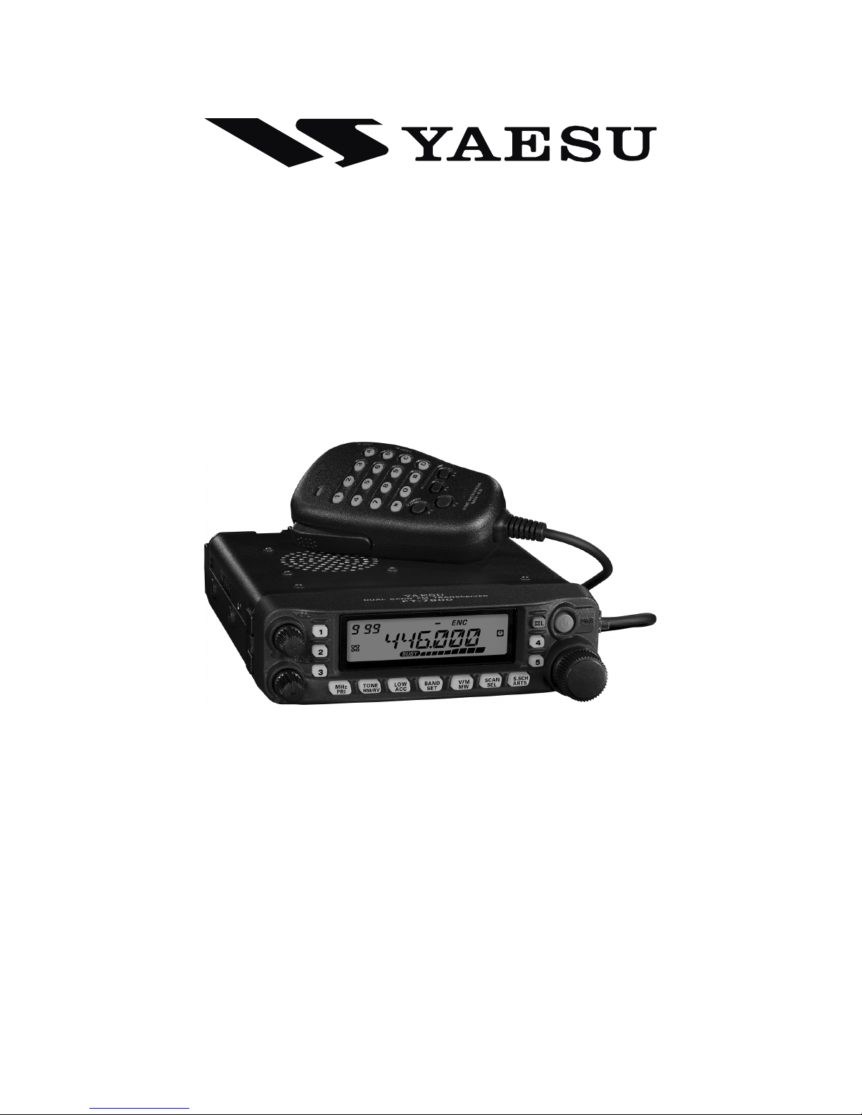
Introduction ...................................................... 1
Specifications .................................................... 2
Accessories & Options ...................................... 3
Supplied Accessories ..................................... 3
Optional Accessories ...................................... 3
Installation ........................................................ 4
Preliminary Inspection ................................... 4
Installation Tips .............................................. 4
Safety Information .......................................... 5
Antenna Considerations ................................. 6
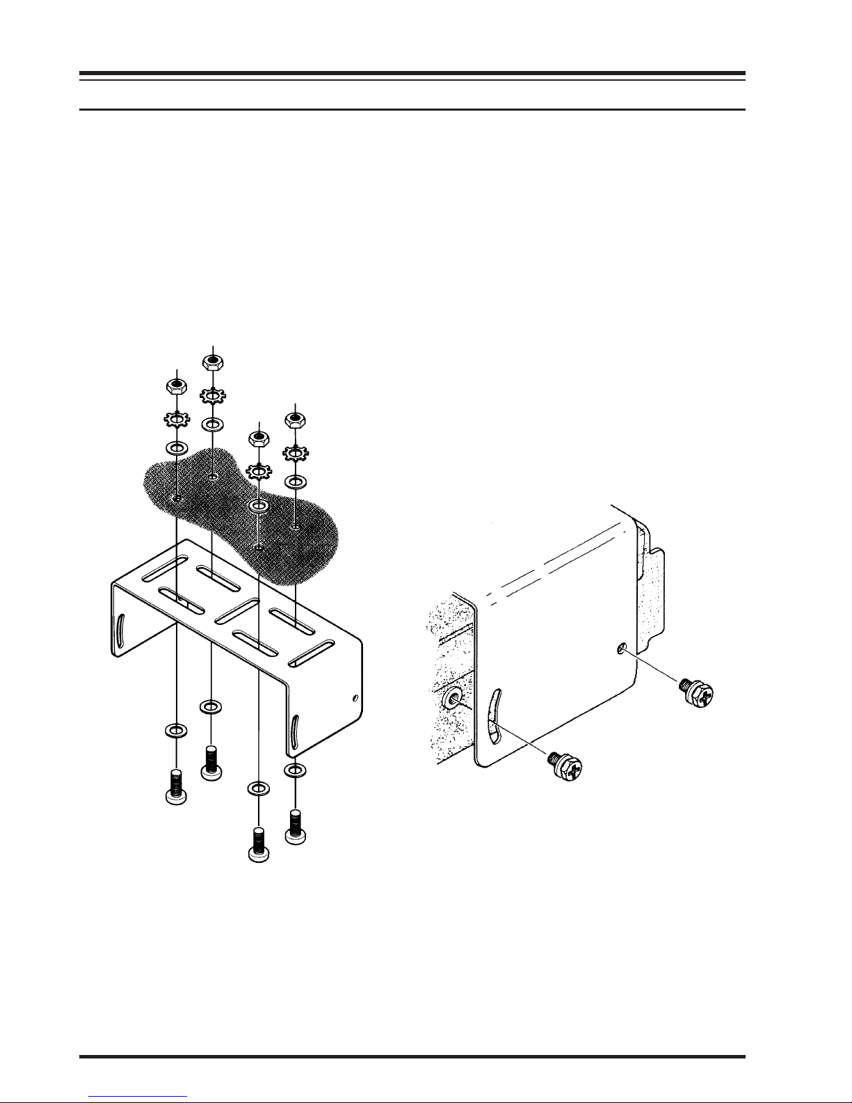
Mobile Installation ......................................... 8
Mobile Power Connections ........................ 9
Mobile Speakers ......................................... 9
Base Station Installation .......................... 10
AC Power Supplies .................................. 10
Packet Radio Terminal Node Controller ..... 10
Front Panel Controls & Switches .................. 12
Side Panel Connection & Knob ..................... 14
LCD .............................................................. 14
Rear Panel Connections ................................. 15
MH-48A6J Microphone ................................... 16
MH-42B6JS Microphone .................................. 18
Basic Operation .............................................. 20
Turning the Transceiver On and Off ............ 20
Adjusting the Audio Volume Level and
Squelch Setting ........................................ 20
Selecting the Operating Band ....................... 20
Frequency Navigation .................................. 21
Transmission ................................................ 22
Changing the Transmitter Power Level ... 22
Advanced Operation ...................................... 23
Lock Feature ................................................. 23
Keyboard Beeper .......................................... 23
Display Brightness ....................................... 24
RF Squelch ................................................... 24
Channel Step Selection ................................ 25
Receiving Mode Selection ........................... 25
Repeater Operation ........................................ 26
Repeater Shifts ............................................. 26
Automatic Repeater Shift (ARS) .................. 26
Manual Repeater Shift Activation ................ 27
Changing the Default Repeater Shift ....... 27
CTCSS/DCS Operation .................................. 28
CTCSS Operation ......................................... 28
DCS Operation ............................................. 29
Tone Search Scanning .................................. 30
Split Tone Operation .................................... 31
Memory Operation ......................................... 32
Regular Memory Channel Operation ........... 33
Memory Storage ....................................... 33
To Append an Alpha-numeric “Tag”
to a Memory ......................................... 33
Storing Independent
Transmit Frequencies (“Odd Splits”) ..... 34
Memory Recall ......................................... 35
Memory Offset Tuning ............................ 35
Deleting Memories ................................... 36
HOME Channel Memory ......................... 36
Memory Bank Operation ......................... 38
Memory Only Mode ................................. 39
Hyper Memory Channel Operation .............. 40
Hyper Memory Storage ............................ 40
Hyper Memory Recall .............................. 40
Weather Broadcast Channel Operation ........ 41
Scanning .......................................................... 42
Setting the Scan-Resume Technique ............ 42
VFO Scanning .............................................. 43
Memory Scanning ........................................ 44
How to Skip (Omit) a Channel
During Memory Scan Operation .............. 44
Preferential Memory Scan ....................... 45
Memory Bank Scan .................................. 46
Weather Alert Scan .................................. 46
Programmable (Band Limit) Memory Scan .... 47
“Priority Channel” Scanning (Dual Watch) .... 48
VFO Priority ............................................ 48
Memory Priority ....................................... 48
HOME Priority ......................................... 48
WX Priority .............................................. 49
Priority Revert Mode ............................... 49
Smart Search ................................................... 50
ARTSTM:
Auto Range Transponder System
...... 52
Basic ARTS Setup and Operation ................ 52
ARTS Polling Time Options ........................ 53
ARTS Alert Beep Option ............................. 53
CW Identifier Setup ..................................... 54
DTMF Autodialer Operation ........................ 56
Internet Connection Feature ......................... 58
Miscellaneous Settings .................................... 60
Time-Out Timer ........................................... 60
Automatic Power Off ................................... 60
MIC Gain Control ........................................ 61
Programming the Key Assignment .............. 62
DCS Code Inversion .................................... 64
Reset Procedure .............................................. 65
Cloning ............................................................ 66
Menu (“Set”) Mode ........................................ 67
“Auto” Mode Preset Operating Parameters ... 78

1FT-7900R OPERATING MANUAL
The FT-7900R is a ruggedly-built, high quality Dual Band FM transceiver providing 50
Watts of power output on the 144 MHz Amateur band and 45 Watts on the 430 MHz Ama-
teur band.
The high power output of the FT-7900R is produced by its RD70HVF1 Power MOS FET
amplifier, with a direct-flow heat sink and thermostatically-controlled cooling fan maintain-
ing a safe temperature for the transceiver’s circuitry.
Featuring 1055 memory channels which enable the storage of Independent Transmit Fre-
quencies (“Odd Split”), and built-in CTCSS and DCS encoder/decoder circuits, the
FT-7900R includes also provision for remote-head mounting, utilizing the optional
YSK-7800 Separation Kit, which allows installation even in the most compact of cars.
Additional features include a convenient access key for Vertex Standard’s WIRES™(Wide-
Coverage Internet Repeater Enhancement System), a transmit Time-Out Timer (TOT), Au-
tomatic Power-Off (APO), Automatic Repeater Shift (ARS), plus Yaesu’s exclusive ARTS™
(Auto-Range Transponder System) which “beeps” the user when you move out of communi-
cations range with another ARTSTM equipped station. And an RF squelch circuit allows the
owner to set the squelch to open at a programmable setting of the S-Meter, thus reducing
guesswork in setting the squelch threshold.
We recommend that you read this manual in its entirety, so as to understand fully the many
features of your new FT-7900R transceiver.
INTRODUCTION

2 FT-7900R OPERATING MANUAL
General
Frequency Range: RX: 108.000 - 520.000 MHz,
700.000 - 999.990 MHz (Cellular Blocked)
TX: 144.000 - 148.000 MHz or 144.000 - 146.000 MHz,
430.000 - 450.000 MHz or 430.000 - 440.000 MHz
Channel Steps: 5/10/12.5/15/20/25/50/100 kHz
Modes of Emission: F3E, F2D, F2A
Antenna Impedance: 50 Ohms, unbalanced (Antenna Duplexer built-in)
Frequency Stability: ±5 ppm @ 14 °F ~ +140 °F (–10 °C ~ +60 °C)
Operating Temperature Range: –4 °F ~ +140 °F (–20 °C ~ +60 °C)
Supply Voltage: 13.8 VDC (±15 %), negative ground
Current Consumption (Approx.): RX: 0.5 A (Squelched)
TX: 8.5 A (144 MHz, 50 W)
9 A (430 MHz, 45 W)
Case Size (W x H x D): 5.5” x 1.6” x 6.6” (140 x 41.5 x 168 mm)
(w/o knobs & connectors)
Weight (Approx.): 2.2 lb. (1 kg)
Transmitter
Output Power: 50/20/10/5 W (144 MHz)
45/20/10/5 W (430 MHz)
Modulation Type: Variable Reactance
Maximum Deviation: ±5 kHz, ±2.5 kHz
Spurious Radiation: At least –60 dB below
Microphone Impedance:2kΩ
DATA Jack Impedance: 10 kΩ
Receiver
Circuit Type: Double-conversion superheterodyne
Intermediate Frequencies: 45.05 MHz/450 kHz
Sensitivity: 0.8 μV (TYP) for 10 dB SN (108 - 137 MHz, AM)
0.2 μV for 12 dB SINAD (137 - 150 MHz, FM)
0.25 μV for 12 dB SINAD (150 - 174 MHz, FM)
0.3 μV (TYP) for 12 dB SINAD (174 - 222 MHz, FM)
0.25 μV (TYP) for 12 dB SINAD (222 - 300 MHz, FM)
0.8 μV (TYP) for 10 dB SN (300 - 336 MHz, AM)
0.25 μV for 12 dB SINAD (336 - 420 MHz, FM)
0.2 μV for 12 dB SINAD (420 - 520 MHz, FM)
0.4 μV (TYP) for 12 dB SINAD (800 - 900 MHz, FM)
0.8 μV (TYP) for 12 dB SINAD (900 - 999.99 MHz, FM)
Squelch Sensitivity: Better than 0.16 μV
Selectivity (–6dB/–60dB): 12 kHz/30 kHz
Maximum AF Output: 2 W @ 8 Ωfor 10% THD
AF Output Impedance: 4-16 Ω
Specifications are subject to change without notice, and are guaranteed within the 144 and
430 MHz amateur bands only. Frequency ranges will vary according to transceiver ver-
sion; check with your dealer.
SPECIFICATIONS

3FT-7900R OPERATING MANUAL
SUPPLIED ACCESSORIES
Microphone MH-48A6J ...................................................................................................... 1
Mobile Mounting Bracket MMB-36 .................................................................................. 1
DC Power Cord w/Fuse (T9021715) .................................................................................. 1
Spare Fuse 15 A (Q0000081) ............................................................................................. 2
Operating Manual ............................................................................................................... 1
Warranty Card ..................................................................................................................... 1
OPTIONAL ACCESSORIES
MH-48A6J DTMF MicrophoneÚ1
MH-42B6JS Hand MicrophoneÚ1
YSK-7800 Separation Kit
MEK-2 Microphone Extension KitÚ2
MLS-100 High-Power External Speaker
FP-1023 AC Power Supply (25A: USA only)
FP-1030A AC Power Supply (25A)
CT-39A Packet Interface Cable
Availability of accessories may vary. Some accessories are supplied as standard per local
requirements, while others may be unavailable in some regions. Consult your Yaesu dealer
for details regarding these and any newly-available options Connection of any non-Yaesu-
approved accessory, should it cause damage, may void the Limited Warranty on this appa-
ratus.
Ú1: If you replace the microphone from the MH-48A6J to MH-42B6JS or vice versa, change
the setting of Menu #22 (MICMIC
MICMIC
MIC). See page 73 for details.
Ú2: When using the MH-48A6J or MH-42B6JS microphone in conjunction with the MEK-
2, in some cases, the programmable key functions (MH-48A6J: [P1]through [P4],
MH-42B6JS: [ACC], [P], [P1], and [P2]) may operate erratically.
ACCESSORIES & OPTIONS

4 FT-7900R OPERATING MANUAL
This chapter describes the installation procedure for integrating the FT-7900R into a typi-
cal amateur radio station. It is presumed that you possess technical knowledge and concep-
tual understanding consistent with your status as a licensed radio amateur. Please take some
extra time to make certain that the important safety and technical requirements detailed in
this chapter are followed closely.
PRELIMINARY INSPECTION
Inspect the transceiver visually immediately upon opening the packing carton. Confirm that
all controls and switches work freely, and inspect the cabinet for any damage. Gently shake
the transceiver to verify that no internal components have been shaken loose due to rough
handling during shipping.
If any evidence of damage is discovered, document it thoroughly and contact the shipping
company (or your local dealer, if the unit was purchased over-the-counter) so as to get
instructions regarding the prompt resolution of the damage situation. Be certain to save the
shipping carton, especially if there are any punctures or other evidence of damage incurred
during shipping; if it is necessary to return the unit for service or replacement, use the origi-
nal packing materials but put the entire package inside another packing carton, so as to
preserve the evidence of shipping damage for insurance purposes.
INSTALLATION TIPS
To ensure long life of the components, be certain to provide adequate ventilation around the
cabinet of the FT-7900R.
Do not install the transceiver on top of another heat-generating device (such as a power
supply or amplifier), and do not place equipment, books, or papers on top of the FT-7900R.
Avoid heating vents and window locations that could expose the transceiver to excessive
direct sunlight, especially in hot climates. The FT-7900R should not be used in an environ-
ment where the ambient temperature exceeds +140 °F (+60 °C).
INSTALLATION

5FT-7900R OPERATING MANUAL
SAFETY INFORMATION
The FT-7900R is an electrical apparatus, as well as a generator of RF (Radio Frequency)
energy, and you should exercise all safety precautions as are appropriate for this type of
device. These safety tips apply to any device installed in a well-designed amateur radio
station.
Never allow unsupervised children to play in the vicinity of your transceiver or an-
tenna installation.
Be certain to wrap any wire or cable splices thoroughly with insulating electrical
tape, to prevent short circuits.
Do not route cables or wires through door jambs or other locations where, through
wear and tear, they may become frayed and shorted to ground or to each other.
Do not stand in front of a directional antenna while you are transmitting into that
antenna. Do not install a directional antenna in any location where humans or pets
may be walking in the main directional lobe of the antenna’s radiation pattern.
In mobile installations, it is preferable to mount your antenna on top of the roof of the
vehicle, if feasible, so as to utilize the car body as a counterpoise for the antenna and
raise the radiation pattern as far away from passengers as possible.
During vehicular operation when stopped (in a parking lot, for example), make it a
practice to switch to Low power if there are people walking nearby.
Never wear dual-earmuff headphones while driving a vehicle.
Do not attempt to drive your vehicle while making a telephone call on an autopatch
using the DTMF microphone. Pull over to the side of the road, whether dialing manu-
ally or using the auto-dial feature.
INSTALLATION

6 FT-7900R OPERATING MANUAL
ANTENNA CONSIDERATIONS
The FT-7900R is designed for use with antennas presenting an impedance of near 50 Ohms
at all operating frequencies. The antenna (or a 50 Ohm dummy load) should be connected
whenever the transceiver is turned on, to avoid damage that could otherwise result if trans-
mission occurs accidentally without an antenna.
Ensure that your antenna is designed to handle 50 Watts of transmitter power. Some mag-
netic-mount mobile antennas, designed for use with hand-held transceivers, may not be
capable of withstanding this power level. Consult the antenna manufacturer’s specification
sheet for details.
Most all FM work is performed using vertical polarization. When installing a directional
antenna such as a Yagi or Cubical Quad, be certain to orient it so as to produce vertical
polarization, unless you are engaged in a special operating situation where horizontal polar-
ization is used. In the case of a Yagi antenna, orient the elements vertically for vertical
polarization; for a Cubical Quad, the feedpoint should be at the center of one of the vertical
sides of the driven element (or at a side corner, in the case of a diamond-shaped Cubical
Quad).
Note that this transceiver is designed with wide frequency coverage in the VHF/UHF spec-
trum. For general listening, you may wish to have a broadband antenna such as a discone
available, as a directional antenna such as a Yagi will have degraded performance outside
the Amateur band for which it is designed.
Excellent reference texts and computer software are available for the design and optimiza-
tion of VHF and UHF antennas. Your dealer should be able to assist you with all aspects of
your antenna installation requirements.
Use high-quality 50 Ohm coaxial cable for the lead-in to your FT-7900R transceiver. All
efforts at providing an efficient antenna system will be wasted if poor quality, lossy coaxial
cable is used. Losses in coaxial lines increase as the frequency increases, so an 8-meter-long
(25’) coaxial line with under 1 dB of loss at 144 MHz may have a loss of 3 dB or more at 446
MHz; choose your coaxial cable carefully based on the installation location (mobile vs.
base) and the overall length of the cable required (for very short runs of cable in a mobile
installation, the smaller, more flexible cable types may be acceptable).
INSTALLATION

7FT-7900R OPERATING MANUAL
INSTALLATION
ANTENNA CONSIDERATIONS
For reference, the chart below shows approximate loss figures for typically-available co-
axial cables frequently used in VHF/UHF installations.
Loss in dB per 30 m (100 feet) for Selected 50-Ohm Coaxial Cables
(Assumes 50-Ohm Input/Output Terminations)
Loss figures are approximate; consult cable manufacturers’ cata-
logs for complete specifications.
In outdoor installations, be certain to weatherproof all connectors thoroughly, as water en-
tering a coaxial cable will cause losses to escalate rapidly, thus diminishing your communi-
cations effectiveness. The use of the shortest possible length of the highest quality coaxial
cable that fits within your budget will ensure the best performance from your FT-7900R.
CABLE TYPE
RG-58A
RG-58 Foam
RG-213
RG-8 Foam
Belden 9913
Times Microwave LMR-400
7/8” “Hardline”
LOSS: 144 MHZ
6.5
4.7
3.0
2.0
1.5
1.5
0.7
LOSS: 430 MHZ
> 10
8
5.9
3.7
2.9
2.6
1.3

8 FT-7900R OPERATING MANUAL
MOBILE INSTALLATION
The FT-7900R must only be installed in vehicles having a 13.8 Volt negative ground elec-
trical system. Mount the transceiver where the display, controls, and microphone are easily
accessible, using the supplied MMB-36 mounting bracket.
The transceiver may be installed in almost any location, but should not be positioned near a
heating vent nor anywhere where it might interfere with driving (either visually or mechani-
cally). Make sure to provide plenty of space on all sides of the transceiver so that air can
flow freely around the radio’s case. Refer to the diagrams showing proper installation proce-
dures.
INSTALLATION

9FT-7900R OPERATING MANUAL
Cabin Engine Room
FT-7900R
Battery
RED: Positive (+)
BLACK: Negative (–)
Mobile Power Connections
To minimize voltage drop and avoid blowing the vehicle’s fuses, connect the supplied DC
power cable directly to the battery terminals. Do not attempt to defeat or bypass the DC
cable’s fuse - it is there to protect you, your transceiver, and your vehicle’s electrical system.
Warning!
Never apply AC power to the power cable of the FT-7900R, nor DC voltage greater
than 15.8 Volts. When replacing the fuse, only use a 15-A fast-blow type. Failure
to observe these safety precautions will void the Limited Warranty on this product.
Before connecting the transceiver, check the voltage at the battery terminals while rev-
ving the engine. If the voltage exceeds 15 Volts, adjust the vehicle’s voltage regulator
before proceeding with installation.
Connect the RED power cable lead to the POSITIVE (+) battery terminal, and the BLACK
power cable lead to the NEGATIVE (–) terminal. If you need to extend the power cable,
use #12 AWG or larger insulated, stranded copper wire. Solder the splice connections
carefully, and wrap the connections thoroughly with insulating electrical tape.
Before connecting the cable to the transceiver, verify the voltage and polarity of the
voltage at the transceiver end of the DC cable using a DC voltmeter. Now connect the
transceiver to the DC cable.
MOBILE INSTALLATION
INSTALLATION
Mobile Speakers
The optional MLS-100 External Speaker includes its own swivel-type mounting bracket,
and is available from your Yaesu dealer.
Other external speakers may be used with the FT-7900R, if they present the specified 8-Ohm
impedance and are capable of handling the 2 Watts of audio output supplied by the FT-7900R.
WARNNING!
Never remove the FUSE holders
from the DC cable.

10 FT-7900R OPERATING MANUAL
BASE STATION INSTALLATION
The FT-7900R is ideal for base station use as well as in mobile installations. The
FT-7900R is specifically designed to integrate into your station easily, using the informa-
tion to follow as a reference.
AC Power Supplies
Operation of the FT-7900R from an AC line requires a power source capable of providing
at least 10 Amps continuously at 13.8 Volts DC. The FP-1023 and FP-1030A AC Power
Supplies are available from your Yaesu dealer to satisfy these requirements. Other well-
regulated power supplies may be used, as well, if they meet the above voltage and current
specifications.
Use the DC power cable supplied with your transceiver for making power connections to the
power supply. Connect the RED power cable lead to the POSITIVE (+) power supply
terminal, and connect the BLACK power cable lead to the NEGATIVE (–) power supply
terminal.
Packet Radio Terminal Node Controller (TNC)
The FT-7900R provides a convenient rear-panel DATA jack for easy connections to your
TNC. This connector is a standard mini-DIN connector. A pre-wired connector and cable
assembly option, model CT-39A, is available from your local Yaesu dealer.
The FT-7900R’s DATA jack connections are optimized for the data transmission and recep-
tion speed in use. In accordance with industry standards, the signal levels, impedances, and
bandwidths are significantly different on 9600 bps as opposed to 1200 bps. If your TNC
does not provide multiple lines to accommodate such optimization, you may still be able to
utilize your TNC, if it is designed for multiple-radio use, by connecting the TNC “Radio 1”
port to the 1200 bps lines on the FT-7900R, and the “Radio 2” port to the 9600 bps lines.
The pin connections of the Data connector are shown below.
INSTALLATION
Pin
1
2
3
4
5
6
Label
PKD
(DATA IN)
GND
PTT
RX9600
RX1200
PKS
(SQL)
Note
Packet Data Input
Impedance: 10 kΩ,
Maximum Input Level: 40 mV p-p for 1200 bps
2.0 Vp-p for 9600 bps
Signal Ground
Gound to Transmit
9600 bps Packet Data Output
Impedance: 10 kΩ, Maximum Output: 500 mV p-p
1200 bps Packet Data Output
Impedance: 10 kΩ, Maximum Output: 300 mV p-p
Squelch Control
Squelch Open: +5 V, Squelch Close: 0 V
CT-39A Wire Color
Brown
Red
Orange
Yellow
Green
Blue

11FT-7900R OPERATING MANUAL
BASE STATION INSTALLATION
INSTALLATION
Note that 9600 bps packet transmit-deviation adjustment is very critical to successful opera-
tion, and can only be accomplished using a calibrated deviation meter (such as that found on
an FM Service Monitor used in a communications service center). In most cases, the Packet
Data Input level (set via a potentiometer inside the TNC) must be adjusted to provide a
deviation of ±2.75 kHz (±0.25 kHz). Check with your packet node’s sysop if you have any
questions about the appropriate deviation level for your network. Note also that high through-
put on 9600 bps frequently requires strong signals, so you may wish to consider the use of a
directional antenna such as a Yagi for communication with high-speed packet nodes.
The setting of the 1200 bps Packet Data Input level is much less critical than it is at 9600 bps,
and satisfactory adjustment to the optimum (±2.5 ~ ±3.5 kHz) deviation can usually be done
“by ear” by adjusting the TNC’s 1200 bps TX Audio Level potentiometer so that the outgoing
packets (as monitored on a separate VHF or UHF receiver) are approximately the same level
as (A) the DTMF tones or (B) the 1750 Hz Burst tone produced using the microphone.
Finally, note that the Menu (“Set”) mode allows you to set the Packet data rate (1200 or
9600 bps) independently for each band. If you have trouble getting your FT-7900R to
respond correctly during packet operation, check to be certain that you do not have Menu
#26 (PKT.SPDPKT.SPD
PKT.SPDPKT.SPD
PKT.SPD) set to the wrong data rate.
You may activate the microphone input while operating on the packet mode via the Menu
#25 (PKT.MICPKT.MIC
PKT.MICPKT.MIC
PKT.MIC), if desired. Generally, we do not recommend this, as a “live” microphone’s
audio input will tend to reduce throughput by interfering with the packets being transmitted
by your radio.
9600 BPS PACKET SETUP
1200 BPS PACKET SETUP
DATA
OUT
DATA
IN PTT
PKS
GND
DATA IN
DATA OUT
(1200bps)
DATA
OUT
DATA
IN PTT
PKS
GND
DATA IN
DATA OUT
(9600bps)

12 FT-7900R OPERATING MANUAL
VOL Knob
This control adjusts the volume level of the receiver’s audio. Clockwise rotation in-
creases the audio level.
SQL Knob
This control sets the threshold level at which received signals (or noise) will open the
squelch. It should be advanced clockwise just to the point where the noise is silenced
(and the “ ” indicator on the display turns off), so as to provide the best sensitiv-
ity to weak signals.
Hyper Memory Buttons ([1]~ [5])
Press and hold in one of these buttons for 2 seconds to store the current total configura-
tion of the radio into a special “Hyper” memory bank.
Press the appropriate button momentarily to recall the desired “Hyper” memory.
[MHz(PRI)] Key
Press this key momentarily to allow tuning in 1-MHz steps on the VFO frequency while
operating on the VFO mode. In the Memory mode, press this key momentarily to allow
tuning in 10 channel steps on the memory channels.
Press and hold in this key for 1/2 second to activate the Priority Channel Scanning (Dual
Watch feature).
[TONE(HM/RV)] Key
Press this key momentarily to change the Tone Squelch mode: ENC (CTCSS Encoder),
ENC.DEC (CTCSS Tone Squelch), or DCS (DCS) operation.
Press and hold in this key for 1/2 second to reverse the transmit and receive frequencies
during split-frequency (i.e. “Repeater”) operation.
FRONT PANEL CONTROLS & SWITCHES

13FT-7900R OPERATING MANUAL
FRONT PANEL CONTROLS & SWITCHES
[LOW(ACC)] Key
Press this key momentarily to select the transmitter power output level (“LOW”, “MID2”,
“MID1”, or “HIGH”).
Press and hold in this key for 1/2 second to recall the Weather Broadcast Channels.
You can program the alternate (press and hold in) function of this key to another func-
tion, if desired. See page 60 for details.
[BAND(SET)] Key
While operating on the VFO mode, press this key momentarily to toggle the operating
band as follows:
144 MHz 250 MHz 350 MHz 430 MHz 850 MHz 144 MHz ......
In the Memory mode, press this key momentarily to activate the “Memory Tune” func-
tion.
Press and hold in this key for 1/2 second to enter the Set (“Menu”) mode.
[V/M(MW)] Key
Press this key momentarily to switch the frequency control among the VFO, Memory
System, and Home channel.
Press and hold in this key for 1/2 second to transfer the VFO contents into a Memory
register.
[SCAN(SEL)] Key
Press this key momentarily to activate the Scanner.
Press and hold in this key for 1/2 second to select the scan mode.
[S.SCH(ARTS)] Keys
Press this key momentarily to activate the Smart Search feature.
Press and hold in this key for 1/2 second to activate the ARTS feature.
DIAL knob
This 20-position detented rotary switch is the tuning dial for the transceiver. It is used
for most tuning, memory selection, and function setting tasks on the transceiver.
PWR ( ) Switch
Press and hold in this switch for 1/2 second to toggle the transceiver’s power on and off.
[ (L)] Key
Press this key momentarily to activate the Internet Connection Feature.
Press and hold in this key for 1/2 second to toggle the Lockout Feature “on” or “off”.

14 FT-7900R OPERATING MANUAL
MIC Jack (Right Side)
Connect the supplied microphone to this jack.
Front Panel Release Knob (Left Side)
Press this knob to unlock the front panel to detachable the front panel from the
transceiver’s main body for remote-head operation (requires optional YSK-7800 Sepa-
ration Kit).
SIDE PANEL CONNECTION & KNOB
Memory Channel Number
Skip Memory Channel
Preferential Memory Channel
Digital Code Squelch (DCS) Operation
CTCSS Operation
Repeater Shift Direction
Transmission in Progress
Automatic Power-Off Active
Keypad/DIAL Lock Active
9600 bps Packet Mode
S- & PO Meter
BUSY Channel (or Squelch Off)
Midium TX Power Selected
Low TX Power Selected
AM Mode Selected
Menu (“Set”) Mode Active
Internet Connection Feature Active
Priority Channel
Memory Tune Mode Operating Frequency
LCD DISPLAY
: PTT
: MIC
: GND
: +9V
: SW 1(Key Control)
: SW 2 (Key Contol)

15FT-7900R OPERATING MANUAL
ANT Jack
Connect your antenna here, using a type-M plug (for USA version) or type-N plug (for
EXP version) and coaxial cable.
Cooling Fan
The cooling fan rotates during transmission, and for 30 seconds after the radio returns
to the receive mode after transmitting.
When the RF power amplifier’s heat sink reaches a moderately high temperature, the
cooling fan will rotate automatically even if the radio is in the receive mode.
DATA Jack
This 6-pin mini-DIN connector provides simple interfacing to a packet Terminal Node
Controller (TNC) for 1200 bps or 9600 bps operation. The pin connections are shown
on page 10.
EXT SP Jack
This 2-conductor, 3.5-mm mini phone jack provides audio output for an optional speaker.
The optimum load impedance is 8 Ohms. Inserting a plug into this jack disables the
audio path to the transceiver’s internal speaker.
13.8V DC Cable Pigtails
This is the DC power supply connection for the transceiver. Use the supplied DC cable
to connect this pigtail to the car battery or base station DC power supply capable of at
least 10 Amperes (continuous duty). Make certain that the Red lead connects to the
Positive (+) side of the power source, and that the Black lead connects to the Negative
(–) side of the power source.
REAR PANEL CONNECTIONS

16 FT-7900R OPERATING MANUAL
PTT Switch
Press this switch to transmit, and release it to receive.
Keypad
These 16 keys generate DTMF tones during trans-
mission.
In the receive mode, the numeric (0 - 9) keys can
be used for direct frequency entry and/or direct
numeric recall of the Memory channels and the
alphabet (A - D) keys can be used for controls the
transceiver, as follow:
[A]Key:
Press this key momentarily to activate the Smart
Search feature.
Press and hold in this key for 1/2 second to activates the
ARTS feature.
[B]Key:
Press this key momentarily to switch the Memory Channel display between the
“Frequency” format and “Alpha-numeric Tag” format.
[C]Key:
Press this key momentarily to disable the noise squelch action, allowing you to hear
very weak signals near the background noise level.
[D]Key:
Press this key momentarily to allow tuning in 1-MHz steps on the VFO frequency
while operating on the VFO mode. In the Memory mode, this allows tuning in 10-
channel steps on the memory channels.
Press and hold in this key for 1/2 second to activate the Priority Channel Scanning
(Dual Watch) feature.
[P1]/[P2]/[P3]/[P4]Buttons
[P1]button:
This button replicates the functions of the front panel [BAND(SET)] key.
While operating on the VFO mode, press this button momentarily to toggle the
operating band as follows:
144 MHz 250 MHz 350 MHz 430 MHz 850 MHz 144 MHz ......
In the Memory mode, press this button momentarily to activate the “Memory Tune”
function.
Press and hold in this key for 1/2 second to enter the Set (“Menu”) mode.
MH-48A6J MICROPHONE

17FT-7900R OPERATING MANUAL
[P2]button:
This button replicates the functions of the front panel [V/M(MW)] key.
Press this button momentarily to switch the frequency control among the VFO,
Memory System, and Home channel.
Press and hold in this button for 1/2 second to transfer the VFO contents into a
Memory register.
[P3]button:
This button replicates the functions of the front panel [TONE(REV)] key.
Press this button momentarily to change the Tone Squelch mode: ENC (CTCSS
Encoder), ENC.DEC (CTCSS Tone Squelch), or DCS (DCS) operation.
Press and hold in this key for 1/2 second to reverse the transmit and receive fre-
quencies during split-frequency (i.e. “Repeater”) operation.
[P4]button:
This button replicates the functions of the front panel [LOW(ACC)] key.
Press this button momentarily to select the transmitter power output level (“LOW”,
“MID2”, “MID1”, or “HIGH”).
Press and hold in this key for 1/2 second to recall the Weather Broadcast Channels.
You can program the [P1], [P2], [P3], and [P4]buttons for other functions, if desired.
See page 62 for details.
LAMP Switch
This switch illuminates the Microphone’s keypad.
LOCK Switch
This switch locks out the Microphone’s buttons (except for the keypad and PTT switch).
[UP]/[DWN]Button
Press (or hold in) either of these buttons to tune (or scan up or down) the operating
frequency or through the memory channels. In many ways, these buttons emulate the
function of the (rotary) DIAL knob.
MH-48A6J MICROPHONE

18 FT-7900R OPERATING MANUAL
The optional MH-42B6JS is similar to the MH-48A6J, but the MH-42B6JS does not include
a DTMF keypad and its illumination switch.
PTT Switch
Press this switch to transmit, and release it to receive.
.[ACC]/[P]/[P1]/[P2]Buttons
[ACC]button:
This button replicates the functions of the
front panel [BAND(SET)] key.
While operating on the VFO mode, press this but-
ton momentarily to toggle the operating band as fol-
lows:
144 MHz 250 MHz 350 MHz
430 MHz 850 MHz 144 MHz ......
In the Memory mode, press this button momentarily to
activate the “Memory Tune” function.
Press and hold in this key for 1/2 second to enter the Set
(“Menu”) mode.
[P]button:
This button replicates the functions of the front panel [V/M(MW)] key.
Press this button momentarily to switch the frequency control among the VFO,
Memory System, and Home channel.
Press and hold in this button for 1/2 second to transfer the VFO contents into a
Memory register.
[P1]button:
This button replicates the functions of the front panel [TONE(REV)] key.
Press this button momentarily to change the Tone Squelch mode: ENC (CTCSS
Encoder), ENC.DEC (CTCSS Tone Squelch), or DCS (DCS) operation.
Press and hold in this key for 1/2 second to reverse the transmit and receive fre-
quencies during split-frequency (i.e. “Repeater”) operation.
[P2]button:
This button replicates the functions of the front panel [LOW(ACC)] key.
Press this button momentarily to select the transmitter power output level (“LOW”,
“MID2”, “MID1”, or “HIGH”).
Press and hold in this key for 1/2 second to recall the Weather Broadcast Channels.
You can program the [ACC], [P], [P1], and [P2]buttons for other functions, if desired.
See page 62 for details.
MH-42B6JS MICROPHONE
Other manuals for FT-7900R
1
Table of contents
Other Yaesu Transceiver manuals

Yaesu
Yaesu FTDX-9000MP User manual

Yaesu
Yaesu FT-747GX Manual

Yaesu
Yaesu FT-1500M User manual

Yaesu
Yaesu FTDX1200 Series Manual

Yaesu
Yaesu FT-980 User manual

Yaesu
Yaesu FTDX-9000D General instructions

Yaesu
Yaesu FTDX10 Manual

Yaesu
Yaesu FT-4VR User manual

Yaesu
Yaesu FTM-400DR User manual

Yaesu
Yaesu FT-200 User manual

Yaesu
Yaesu FTDX-9000MP User manual

Yaesu
Yaesu FT-2311R User manual

Yaesu
Yaesu FTM-7250DR User manual

Yaesu
Yaesu FT-290R II Manual

Yaesu
Yaesu FTDX-9000D User manual

Yaesu
Yaesu FT-902DM User manual

Yaesu
Yaesu FT-101 User manual

Yaesu
Yaesu FTM-200DR User manual

Yaesu
Yaesu FT-2980R User manual

Yaesu
Yaesu FT-817 - Manual