Contents
Contents......................................................................................................................3
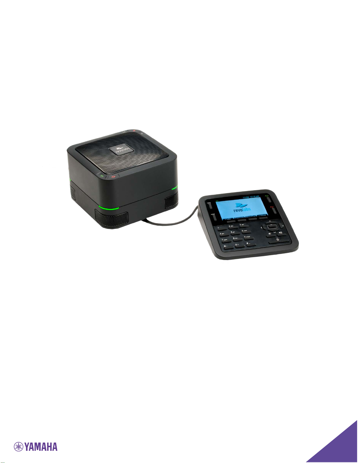
Getting Started with the FLX UC 1000.........................................................................5
Assembling the FLX UC 1000 ...................................................................................5
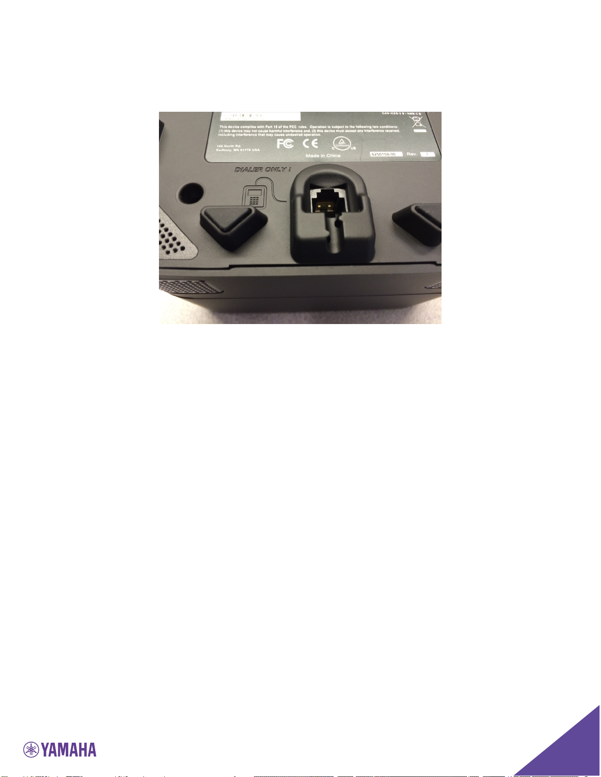
Connecting the Dialer............................................................................................6
Powering up the FLX UC 1000...............................................................................8
Connecting the FLX UC 1000 to a Computer .........................................................9
Understanding the Components of the FLX UC 1000..............................................10
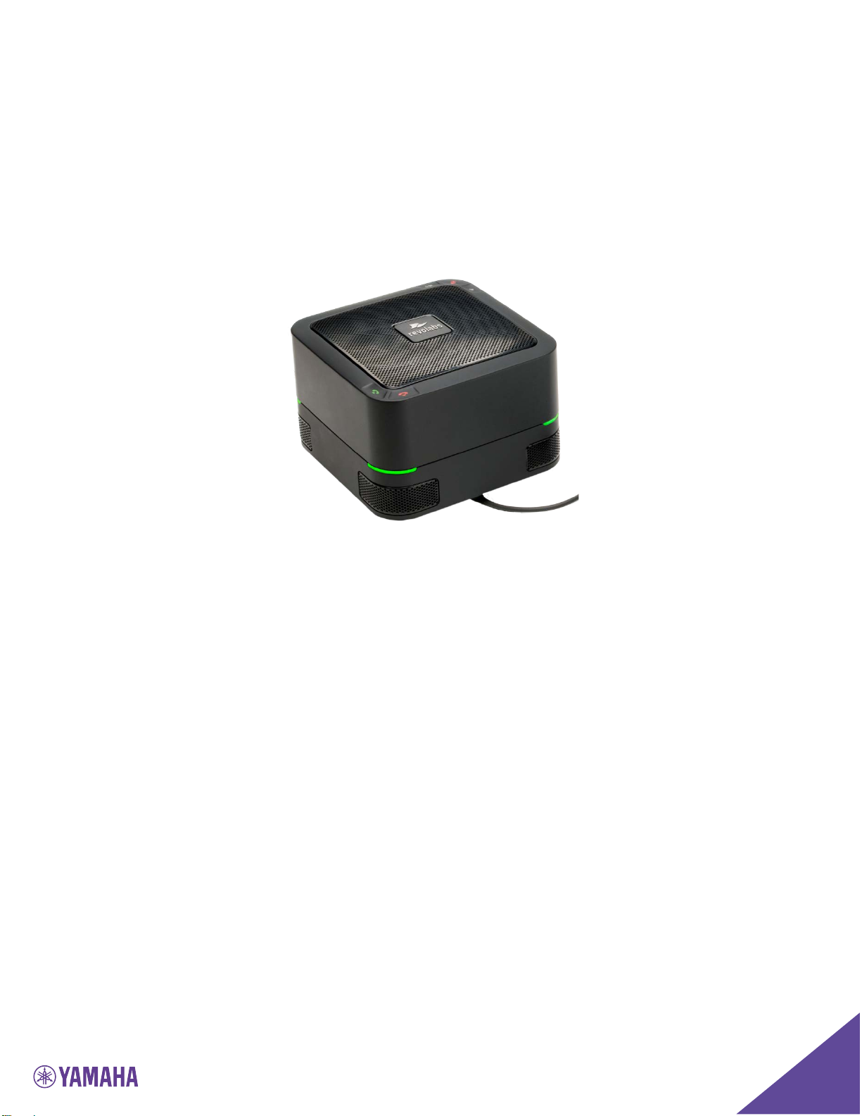
Base Unit ............................................................................................................10
Dialer ..................................................................................................................11
User Interface .........................................................................................................14
Base Unit ............................................................................................................14
Dialer ..................................................................................................................14
Web User Interface (Web UI) ................................................................................20
Basic Operations .......................................................................................................25
Dialing a Number ...................................................................................................25
Redialing a Number ................................................................................................25
Dialing a Contact....................................................................................................25
Making a call while another call is already active....................................................26
Answering an Incoming Call ...................................................................................26
Ignoring an Incoming Call.......................................................................................26
Hanging Up a Call ..................................................................................................26
Using USB Audio on the FLX UC 1000 ...................................................................26
Setting up a Conference Call ..................................................................................27
Using Do Not Disturb .............................................................................................27
Configuring the FLX UC 1000 for your VoIP Network.................................................28
Through the Dialer .................................................................................................28
Through Web User Interface ...................................................................................28
Through Provisioning Server, using Option 66........................................................29
Provisioning configuration file sample.....................................................................30
FLX UC 1000 Device Manager ...................................................................................33
Third Party Applications Supported ........................................................................33