Yamaha RCX222 User manual

RCX222
EUR2153130
E99
Ver. 1.30
UserʼsManual
YAMAHA2-AXISROBOTCONTROLLER


CONTENTS RCX222
User’s Manual
T-1
Safety Instructions
1. Safety Information S-1
2. Signal words used in this manual S-2
3. Warning labels S-3
3.1 Warning labels S-3
3.1.1 Warning label messages on robot and controller S-3
3.1.2 Supplied warning labels S-8
3.2 Warning symbols S-9
4. Important precautions for each stage of the robot life cycle S-10
4.1 Precautions for using robots and controllers S-10
4.2 Essential precautions for the linear conveyor module S-11
4.3 Design S-12
4.3.1 Precautions for robots S-12
4.3.2 Precautions for robot controllers S-12
4.4 Moving and installation S-13
4.4.1 Precautions for robots S-13
4.4.2 Precautions for robot controllers S-14
4.5 Safety measures S-16
4.5.1 Safety measures S-16
4.5.2 Installing a safety enclosure S-17
4.6 Operation S-18
4.6.1 Trial operation S-18
4.6.2 Automatic operation S-20
4.6.3 Precautions during operation S-20
4.7 Inspection and maintenance S-22
4.7.1 Before inspection and maintenance work S-22
4.7.2 Precautions during service work S-23
4.8 Disposal S-24
5. Emergency action when a person is caught by robot S-25
6. Cautionsregardingstrongmagneticelds S-25
7. Using the robot safely S-26
7.1 Movement range S-26
7.2 Robot protective functions S-27
7.3 Residual risk S-28
7.4 Special training for industrial robot operation S-28

CONTENTS RCX222
User’s Manual
T-2
T-3
Warranty
Introduction 1
Before using the robot controller (Be sure to read the following notes) 2
Overview of the RCX series 3
Chapter 1 USING THE ROBOT SAFELY
1. Operating environment 1-1
Chapter 2 SYSTEM OVERVIEW
1. System overview 2-1
1.1 Mainsystemconguration 2-1
1.2 RCX22seriesaxisdenition 2-2
2. Part names and functions 2-3
2.1 RCX222 (Maximum number of axes: 2) 2-3
2.2 RCX222HP (Maximum number of axes: 2) 2-3
3. Control system 2-4
3.1 RCX222/RCX222HP 2-4
4. Optional devices 2-5
4.1 RPB programming box 2-5
4.2 I/O expansion 2-5
4.3 Regenerative unit 2-5
5. Basic sequence from installation to operation 2-6
Chapter 3 INSTALLATION
1. Unpacking 3-1
1.1 Packing box 3-1
1.2 Unpacking 3-1
2. Installing the robot controller 3-2
2.1 Installation conditions 3-2
2.2 Installation methods 3-4
3. Connector names 3-6
4. Connecting to the power 3-7

T-2
CONTENTS RCX222
User’s Manual
T-3
4.1 Connection example 3-7
4.2 Power supply and ground terminals 3-8
4.3 AC power connector wiring 3-9
4.4 Considering power capacity and generated heat amount 3-10
4.5 Installing an external leakage breaker 3-11
4.6 Installing a circuit protector 3-11
4.7 Installing an electromagnetic contactor 3-12
4.8 Installinganoiselter 3-12
4.9 Installing a surge absorber 3-13
5. Robot connections 3-14
5.1 Connecting the robot cables 3-14
5.2 Noise countermeasures 3-15
6. Connecting the RPB programming box 3-16
7. I/O connections 3-17
8. Connecting a host computer 3-18
9. Connecting the absolute battery 3-19
10. Replacing the absolute battery 3-21
11. Connecting a regenerative unit 3-22
12. Precautions for cable routing and installation 3-24
12.1 Wiring methods 3-24
12.2 Precautions for installation 3-26
12.3 Methods of preventing malfunctions 3-26
13. Checking the robot controller operation 3-27
13.1 Cable connection 3-27
13.2 Operation check 3-28
Chapter 4 OPERATION
1. Operation overview 4-1
2. The RCX robot controller 4-2
2.1 Part names 4-2
2.2 Main functions 4-2
3. RPB programming box 4-3

CONTENTS RCX222
User’s Manual
T-4
T-5
3.1 Part names 4-3
3.2 Main functions 4-3
3.3 Connection to the robot controller 4-4
3.4 Changing the RPB screen settings 4-5
4. Turning power on and off 4-6
5. Operation keys 4-8
5.1 RPB screen 4-8
5.2 Operation key layout 4-9
5.3 Basic key operation 4-10
5.4 Function keys 4-11
5.5 Control keys 4-13
5.6 Data keys 4-15
5.7 Other keys 4-15
6. Emergency stop 4-16
6.1 Emergency stop reset 4-17
6.2 Overload error reset 4-19
7. Modeconguration 4-21
7.1 Basic operation modes 4-21
7.2 Other operation modes 4-22
7.3 Mode hierarchy 4-23
8. "SERVICE" mode 4-28
8.1 Operation device 4-28
8.2 Prohibition of "AUTO" mode operation 4-28
8.3 Hold-to-Run function 4-28
8.4 Limits on robot moving speed 4-29
9. "AUTO" mode 4-30
9.1 Automatic operation 4-33
9.2 Stopping the program 4-34
9.3 Resetting the program 4-35
9.4 Switching task display 4-37
9.5 Switching the program 4-38
9.6 Changing the automatic movement speed 4-39
9.7 Executing the point trace 4-40
9.7.1 PTP motion mode 4-42
9.7.2 ARCH motion mode 4-43
9.7.3 Linear interpolation motion mode 4-45
9.8 Direct command execution 4-46

T-4
CONTENTS RCX222
User’s Manual
T-5
9.9 Break point 4-47
9.9.1 Setting break points 4-48
9.9.2 Deleting break points 4-49
9.10 Executing a step 4-50
9.11 Skipping a step 4-50
9.12 Executing the next step 4-51
10. "PROGRAM" mode 4-52
10.1 Scrolling a program listing 4-53
10.2 Program editing 4-54
10.2.1 Cursor movement 4-56
10.2.2 Insert/Overwrite mode switching 4-57
10.2.3 Inserting a line 4-58
10.2.4 Deleting a character 4-58
10.2.5 Deleting a line 4-58
10.2.6 User function key display 4-59
10.2.7 Quitting program editing 4-60
10.2.8 Specifying the copy/cut lines 4-60
10.2.9 Copying the selected lines 4-61
10.2.10Cutting the selected lines 4-61
10.2.11 Pasting the data 4-62
10.2.12Backspace 4-62
10.2.13Line jump 4-63
10.2.14Searching a character string 4-64
10.3 Directory 4-65
10.3.1 Cursor movement 4-67
10.3.2 Registering a new program name 4-67
10.3.3 Directory information display 4-68
10.3.4 Copying a program 4-69
10.3.5 Erasing a program 4-70
10.3.6 Renaming a program 4-71
10.3.7 Changing the program attribute 4-72
10.3.8 Displaying object program information 4-73
10.3.9 Creating a sample program automatically 4-74
10.4 Compiling 4-76
10.5 Line jump and character string search 4-77
10.6 Registering user function keys 4-77
10.7 Resetting an error in the selected program 4-81
11. "MANUAL" mode 4-82
11.1 Manual movement 4-84
11.2 Displaying and editing point data 4-87

CONTENTS RCX222
User’s Manual
T-6
T-7
11.2.1 Point data input and editing 4-89
11.2.1.1 Restoring point data 4-90
11.2.2 Point data input by teaching 4-91
11.2.3 Point data input by direct teaching 4-93
11.2.4 Point jump display 4-94
11.2.5 Copying point data 4-95
11.2.6 Erasing point data 4-97
11.2.7 Point data trace 4-98
11.2.8 Point comment input and editing 4-98
11.2.8.1 Point comment input and editing 4-100
11.2.8.2 Point data input by teaching 4-100
11.2.8.3 Jump to a point comment 4-101
11.2.8.4 Copying a point comment 4-101
11.2.8.5 Erasing point comments 4-103
11.2.8.6 Point comment search 4-104
11.2.9 Point data error reset 4-105
11.3Displaying,editingandsettingpalletdenitions 4-106
11.3.1 Editing pallet definitions 4-108
11.3.1.1 Point setting in pallet definition 4-109
11.3.1.1.1 Editing the point in pallet definition 4-110
11.3.1.1.2 Setting the point in pallet definition by teaching 4-110
11.3.2 Pallet definition by teaching 4-111
11.3.3 Copying a pallet definition 4-114
11.3.4 Deleting a pallet definition 4-115
11.4 Changing the manual movement speed 4-116
11.5 Displaying, editing and setting shift coordinates 4-117
11.5.1 Editing shift coordinates 4-119
11.5.1.1 Restoring shift coordinates 4-120
11.5.2 Editing the shift coordinate range 4-121
11.5.2.1 Restoring a shift coordinate range 4-123
11.5.3 Shift coordinate setting method 1 4-124
11.5.4 Shift coordinate setting method 2 4-127
11.6 Displaying,editingandsettinghanddenitions 4-130
11.6.1 Editing hand definitions 4-133
11.6.1.1 Restoring hand definitions 4-134
11.6.2 Hand definition setting method 1 4-135
11.7 Changing the display units 4-137
11.8 Absolute reset 4-138
11.8.1 Checking absolute reset 4-139
11.8.2 Absolute reset on each axis 4-140
11.8.3 Absolute reset on all axes 4-147
11.9 Setting the standard coordinates 4-153

T-6
CONTENTS RCX222
User’s Manual
T-7
11.10 Executing the user function keys 4-154
12. "SYSTEM" mode 4-155
12.1 Parameters 4-157
12.1.1 Parameter list 4-159
12.1.2 Robot parameters 4-161
12.1.3 Axis parameters 4-165
12.1.4 Other parameters 4-185
12.1.5 Parameters for option boards 4-201
12.1.5.1 Option DIO setting 4-203
12.1.5.2 Serial IO setting 4-204
12.1.5.3 Setting the network parameters 4-209
12.2 Communication parameters 4-211
12.3 OPTION parameters 4-220
12.3.1 Setting the area check output 4-221
12.3.2 Setting the "SERVICE" mode 4-230
12.3.2.1 Saving the "SERVICE" mode parameters 4-236
12.3.2.2 Help display in "SERVICE" mode 4-237
12.3.3 SIO settings 4-238
12.3.4 Double-carrier setting 4-241
12.3.4.1 Before using a double-carrier 4-241
12.3.4.2 Setting the double-carrier parameters 4-242
12.4 Initialization 4-245
12.4.1 Initializing the parameters 4-246
12.4.2 Initializing the memory 4-247
12.4.3 Initializing the communication parameters 4-248
12.4.4 Clock setting 4-249
12.4.5 System generation 4-250
12.5 Self diagnosis 4-251
12.5.1 Controller check 4-252
12.5.2 Error history display 4-253
12.5.3 Displaying the absolute battery condition 4-254
12.5.4 Displaying the total operation time 4-255
12.5.5 System error details display 4-256
12.6 Backup processes 4-257
12.6.1 SD memory card 4-258
12.6.1.1 Loading files 4-260
12.6.1.2 Saving files 4-262
12.6.1.3 Deleting files 4-264
12.6.1.4 Previewing files 4-265
12.6.2 Internal flash ROM 4-266
12.6.2.1 Loading files 4-267

CONTENTS RCX222
User’s Manual
T-8
T-9
12.6.2.2 Saving files 4-269
12.6.2.3 Initializing the files 4-270
13. "MONITOR" mode 4-271
14. "UTILITY" mode 4-274
14.1 Canceling emergency stop; Motor power and servo on/off 4-276
14.1.1 Canceling emergency stop 4-276
14.1.2 Motor power and servo on/off 4-277
14.2 Overload error reset and motor and servo power on/off 4-279
14.2.1 Emergency stop reset 4-279
14.2.2 Overload error reset 4-279
14.3Enabling/disablingthesequenceexecutionag 4-280
14.4 Resetting the output ports 4-281
14.5 Changing the execution level 4-282
14.5.1 Changing the execution level 4-283
14.5.2 Displaying the Help message 4-284
14.6 Changing the access level (operation level) 4-285
14.6.1 Entering the password 4-286
14.6.2 Changing the access level 4-287
14.6.3 Displaying the Help message 4-288
Chapter 5 PARALLEL I/O INTERFACE
1. Standard I/O interface overview 5-1
1.1 ID setting 5-2
1.2 Connector I/O signals 5-3
1.3 Connector pin numbers 5-6
1.4 Connecting the power supply 5-7
1.4.1 NPN/PNP power connector wiring 5-8
1.5 Typical input signal connection 5-9
1.6 Typical output signal connection 5-10
1.7 Dedicated I/O signals 5-11
1.7.1 Dedicated input signals 5-11
1.7.2 Dedicated output signals 5-13
1.8 General-purpose I/O signals 5-15
1.8.1 General-purpose output reset 5-15
1.9 Dedicated I/O signal timing charts 5-16
1.9.1 Turning the power on 5-16
1.9.2 Emergency stop and servo ON 5-18
1.9.3 ABS (absolute) reset 5-19
1.9.4 Mode switching 5-20
1.9.5 Automatic operation 5-21

T-8
CONTENTS RCX222
User’s Manual
T-9
2. Ratings 5-22
3. Precautions 5-23
Chapter 6 SAFETY I/O INTERFACE
1. SAFETY I/O interface overview 6-1
1.1 Power 6-1
1.2 Connector I/O signals 6-2
1.3 Connector terminal numbers 6-3
1.4 Emergency stop input signal connections 6-4
1.5 Dedicated input signal connections 6-10
1.6 Dedicated output signal connections 6-11
1.7 Input signal description 6-13
1.8 Meaning of output signals 6-14
Chapter 7 RS-232C INTERFACE
1. Communication overview 7-1
2. Communication function overview 7-2
3. Communicationspecications 7-3
3.1 Connector 7-3
3.2 Transmission mode and communication parameters 7-5
3.3 Communicationowcontrol 7-6
3.3.1 Flow control during transmit 7-6
3.3.2 Flow control during receive 7-6
3.4 Other caution items 7-7
3.5 Character code table 7-9
3.6 Connecting to a PC 7-10
Chapter 8 SPECIFICATIONS
1. Controllerbasicspecications 8-1
2. Controller basic functions 8-3
3. Controller external view 8-4
3.1 RCX222 external view 8-4
3.2 RCX222HP external view 8-5
4. RPBbasicspecicationsandexternalview 8-6

CONTENTS RCX222
User’s Manual
T-10
Chapter 9 TROUBLESHOOTING
1. Error Messages 9-1
1.1 Robot controller error messages 9-1
[ 0] Warnings and messages 9-3
[ 1] Warnings (error history entry) 9-5
[ 2] Robot operating area errors 9-6
[ 3] Program file operating errors 9-10
[ 4] Data entry and edit errors 9-12
[ 5] Robot language syntax (compiling) errors 9-13
[ 6] Robot language execution errors 9-21
[ 9] Memory errors 9-26
[10] System setting or hardware errors 9-29
[12] I/O and option board errors 9-31
[13] RPB errors 9-35
[14] RS-232C communication errors 9-36
[15] Memory card errors 9-38
[17] Motor control errors 9-40
[19] YC-Link (SR1) related error 9-48
[21] Major software errors 9-54
[22] Major hardware errors 9-56
1.2 RPB Error Messages 9-62
2. Troubleshooting 9-64
2.1 When trouble occurs 9-64
2.2 Acquiring error information 9-65
2.2.1 Acquiring information from the RPB 9-65
2.2.2 Acquiring information from the RS-232C 9-65
2.3 Troubleshooting checkpoints 9-66

Contents
1. Safety Information S-1
2. Signal words used in this manual S-2
3. Warning labels S-3
3.1 Warning labels S-3
3.1.1 Warning label messages on robot and controller S-3
3.1.2 Supplied warning labels S-8
3.2 Warning symbols S-9
4.
Important precautions for each stage of the robot life cycle
S-10
4.1 Precautions for using robots and controllers S-10
4.2 Essential precautions for the linear conveyor module S-11
4.3 Design S-12
4.3.1 Precautions for robots S-12
4.3.2 Precautions for robot controllers S-12
4.4 Moving and installation S-13
4.4.1 Precautions for robots S-13
4.4.2 Precautions for robot controllers S-14
4.5 Safety measures S-16
4.5.1 Safety measures S-16
4.5.2 Installing a safety enclosure S-17
4.6 Operation S-18
4.6.1 Trial operation S-18
4.6.2 Automatic operation S-20
4.6.3 Precautions during operation S-20
4.7 Inspection and maintenance S-22
4.7.1 Before inspection and maintenance work S-22
4.7.2 Precautions during service work S-23
4.8 Disposal S-24
5.
Emergency action when a person is caught by robot
S-25
6. Cautions regarding strong magnetic fields S-25
7. Using the robot safely S-26
7.1 Movement range S-26
7.2 Robot protective functions S-27
7.3 Residual risk S-28
7.4 Special training for industrial robot operation S-28
Safety Instructions


Safety Instructions
S-1
1. Safety Information
Industrial robots are highly programmable, mechanical devices that provide a large degree of freedom when
performing various manipulative tasks. To ensure safe and correct use of YAMAHA industrial robots and con-
trollers*, carefully read and comply with the safety instructions and precautions in this "Safety Instructions"
guide. Failure to take necessary safety measures or incorrect handling may result in trouble or damage to the
robot and controller, and also may cause personal injury (to installation personnel, robot operator or service
personnel) including fatal accidents.
* The descriptions about the controller stated in this manual also include the contents of the robot driver.
Before using this product, read this manual and related manuals and take safety precautions to ensure cor-
rect handling.
The precautions listed in this manual relate to this product. To ensure safety of the user’s final system that in-
cludes YAMAHA robots, please take appropriate safety measures as required by the user’s individual system.
To use YAMAHA robots and controllers safely and correctly, always comply with the safety rules and instruc-
tions.
• Forspecificsafetyinformationandstandards,refertotheapplicablelocalregulationsandcomplywith
the instructions.
• WarninglabelsattachedtotherobotsarewritteninEnglish,Japanese,ChineseandKorean.Thismanual
isavailableinEnglishorJapanese(orsomepartsinChinese).Unlesstherobotoperatorsorservice
personnel understand these languages, do not permit them to handle the robot.
• CautionsregardingtheofficiallanguageofEUcountries
ForequipmentthatwillbeinstalledinEUcountries,thelanguageusedforthemanuals,warninglabels,
operationscreencharacters,andCEdeclarationsisEnglishonly.
WarninglabelsonlyhavepictogramsorelseincludewarningmessagesinEnglish.Inthelattercase,
messagesinJapaneseorotherlanguagesmightbeadded.
It is not possible to list all safety items in detail within the limited space of this manual. So please note that
it is essential that the user have a full knowledge of safety and also make correct judgments on safety proce-
dures.
Refer to the manual by any of the following methods when installing, operating or adjusting the robot
and controller.
1. Install, operate or adjust the robot and controller while referring to the printed version of the
manual (available for an additional fee).
2. Install, operate or adjust the robot and controller while viewing the disc version of the manual
on your computer screen.
3. Install, operate or adjust the robot and controller while referring to a printout of the necessary
pages from the disc version of the manual.

Safety Instructions
S-2
2. Signal words used in this manual
This manual uses the following safety alert symbols and signal words to provide safety instructions that must
be observed and to describe handling precautions, prohibited actions, and compulsory actions. Make sure
you understand the meaning of each symbol and signal word and then read this manual.
wDANGER
This indicates an immediately hazardous situation which, if not avoided, will result in death or serious injury.
wWARNING
This indicates a potentially hazardous situation which, if not avoided, could result in death or serious injury.
cCAUTION
This indicates a potentially hazardous situation which, if not avoided, could result in minor or moderate injury, or
damage to the equipment.
nNOTE
Explains the key point in the operation in a simple and clear manner.

Safety Instructions
S-3
3. Warning labels
Warninglabelsshownbelowareattachedtotherobotbodyandcontrollertoalerttheoperatortopotential
hazards. To ensure correct use, read the warning labels and comply with the instructions.
3.1 Warning labels
wWARNING
If warning labels are removed or difficult to see, then the necessary precautions may not be taken, resulting in an
accident.
outside the safety enclosure.
3.1.1 Warning label messages on robot and controller
Word messages on the danger, warning and caution labels are concise and brief instructions. For more specific
instructions, read and follow the "Instructions on this label" described on the right of each label shown below.
See “7.1 Movement range” in “Safety instructions” for details on the robot’s movement range.
Warning label 1 (SCARA robots, Cartesian robots)
■
wDANGER
Serious injury may result from contact with a moving robot.
Instructions on this label
• Alwaysinstallasafetyenclosuretokeepallpersons
awayfromtherobotmovementrangeandprevent
injuryfromcontactingthemovingpartoftherobot.
•
Installaninterlockthattriggersemergencystopwhen
thedoororgateofthesafetyenclosureisopened.
• Thesafetyenclosureshouldbedesignedsothatno
onecanenterinsideexceptfromthedoororgate
equippedwithaninterlockdevice.
• Warninglabel1thatcomessuppliedwitharobot
shouldbeaffixedtoaneasy-to-seelocationonthe
doororgateofthesafetyenclosure.
Potential hazard to human body Seriousinjurymayresultfromcontactwithamovingrobot.
To avoid hazard •Keepoutsideoftherobotsafetyenclosureduringoperation.
•Presstheemergencystopbuttonbeforeenteringthesafetyenclosure.
90K41-001470
Warning label 2 (SCARA robots, Cartesian robots, single-axis robots*)
■
* Warning label 2 is not attached to some small single-axis robots, but is supplied with the robots.
wWARNING
Moving parts can pinch or crush hands.
Instructions on this label
Usecautiontopreventhandsandfingersfrombeing
pinchedorcrushedbythemovablepartsoftherobot
whentransportingormovingtherobotorduring
teaching.
Potential hazard to human body Movingpartscanpinchorcrushhands.
To avoid hazard Keephandsawayfromthemovablepartsoftherobot.
90K41-001460

Safety Instructions
S-4
Warning label 3 (SCARA robots, Cartesian robots, controllers*)
■
* Some models
wWARNING
Improper installation or operation may cause serious injury.
Before installing or operating the robot, read the manual and instructions on the warning labels and understand
the contents.
Instructions on this label
• Besuretoreadthewarninglabelandthismanual
carefullytomakeyoucompletelyunderstandthe
contentsbeforeattemptinginstallationandoperation
oftherobot.
• Beforestartingtherobotoperation,evenafteryou
havereadthroughthismanual,readagainthe
correspondingproceduresand"Safetyinstructions"
inthismanual.
• Neverinstall,adjust,inspectorservicetherobotin
anymannerthatdoesnotcomplywiththe
instructionsinthismanual.
Potential hazard to human body Improperinstallationoroperationmaycauseseriousinjury.
To avoid hazard Beforeinstallingoroperatingtherobot,readthemanualandinstructionsonthe
warninglabelsandunderstandthecontents.
90K41-001290
Warning label 4 (SCARA robots*)
■
* This label is not attached to omnidirectional type SCARA robots.
cCAUTION
Do not remove the parts on which Warning label 4 is attached.
Doing so may damage the ball screw.
Instructions on this label
TheZ-axisballscrewwillbedamagediftheupperend
mechanicalstopperontheZ-axissplineisremovedor
moved.Neverattempttoremoveormoveit.
90K41-001520
Warning label 5 (Cartesian robots*, single-axis robots*)
■
* Some robot models
wWARNING
Ground the controller to prevent electrical shock.
Ground terminal is located inside this cover.
Read the manual for details.
Instructions on this label
• Highvoltagesectioninside
• Topreventelectricalshock,besuretogroundthe
robotusingthegroundterminal.
Potential hazard to human body Electricalshock
To avoid hazard Groundthecontroller.
90K41-001480

Safety Instructions
S-5
Warming label 6 (Robot drivers RDV-X/RDV-P)
■
wWARNING
10 minutes or longer to prevent electrical shock. Otherwise, burn or electrical shock may result.
Instructions on this label
• Thisindicatesahighvoltageispresent.
Touchingtheterminalblockorconnectormaycause
electricalshock.
• Thisindicatesimportantinformationthatyoumust
knowisdescribedinthemanual.
Beforeusingtherobotdriver,besuretoreadthe
manualthoroughly.
• Besuretogroundthegroundterminaltoavoid
electricalshock.
• Usenonflammablemetalplatesforthematerialof
theinstallationwallsurface.
Otherwise,firemayresult.
Potential hazard to human body To avoid hazard
Electricalshock Donottouchtheterminalsectionfor10minutesafterpower-off.
Improperinstallationoroperationmaycause
seriousinjury.
Beforeinstallingoroperatingtherobot,readthemanualandinstructions
onthewarninglabelsandunderstandthecontents.
Electricalshock Besuretogroundthegroundterminal.
3T034156-1/NE63012
Warming label 7 (controllers TS-X/TS-P)
■
wWARNING
10 minutes to avoid burns or electrical shock.
cCAUTION
Instructions on this label
• Thisindicatesahighvoltageispresent.
Touchingtheterminalblockorconnectormaycause
electricalshock.
• Thisindicatestheareaaroundthissymbolmay
becomeveryhot.
Motorsandheatsinksbecomehotduringandshortly
afteroperation.Donottouchthemtoavoidburns.
• Thisindicatesimportantinformationthatyoumust
knowisdescribedinthemanual.
Beforeusingthecontroller,besuretoreadthe
manualthoroughly.
Whenaddingexternalsafetycircuitsorconnectinga
powersupplytothecontroller,readthemanual
carefullyandmakechecksbeforebeginningthe
work.
• Besuretogroundthegroundterminaltoavoid
electricalshock.
Potential hazard to human body To avoid hazard
Electricalshock Donottouchtheterminalsectionfor10minutesafterpower-off.
Donottouchthemtoavoidburns. Donottouchthemotorsandheatsinksduringpower-on.
Improperinstallationoroperationmaycause
seriousinjury.
Beforeinstallingoroperatingtherobot,readthemanualandinstructions
onthewarninglabelsandunderstandthecontents.
Electricalshock Besuretogroundthegroundterminal.
90K41-000950

Safety Instructions
S-6
Warming label 8 (controllers RCX240, controllers RCX340)
■
wWARNING
These are precautions for YAMAHA and distributors' service personnel.
Customers must not attempt to open the covers.
wWARNING
Wait at least 100 seconds after power-off before opening the covers.
Instructions on this label
• Waitatleast100secondsafterpower-off
beforeopeningthecovers(*).
• Somepartsinthecontrollerstillretainahigh
voltageevenafterpower-off,soelectrical
shockmayoccurifthosepartsaretouched.
Potential hazard to human body Electricalshock
To avoid hazard Waitatleast100secondsafterpower-offbeforeopeningthecovers(*).
* These are precautions for YAMAHA and distributors' service personnel. Customers must not attempt to open the covers.
90K41-001390
Warning label 9 (single-axis linear motor robots)
■
cCAUTION
A magnetic scale is located inside this cover. Bringing a magnet close to it may cause malfunction.
Instructions on this label
• Topreventtherobotfromoperatingimproperlydue
tomagneticscalemalfunction,donotbringastrong
magnettothecover.
• Donotbringtoolsclosetothemagneticscale.
90K41-001510
Warning label 10 (single-axis linear motor robots)
■
cCAUTION
Powerful magnets are installed in the robot.
Do not attempt to disassemble the robot to avoid possible injury.
Do not bring any device that may malfunction due to magnetic fields close to the robot.
Instructions on this label
Besuretoread"6.Cautionsregardingstrongmagnetic
fields"in"Safetyinstructions"andmakesureyoufully
understanditscontentsbeforehandlingoroperating
therobot.
Potential hazard to human body Injuryordeathmayresultinsomecases.
To avoid hazard Makeyouunderstandtheprecautionsregardingstrongmagneticfields.
90K41-001500
Other manuals for RCX222
1
Table of contents
Other Yamaha Controllers manuals

Yamaha
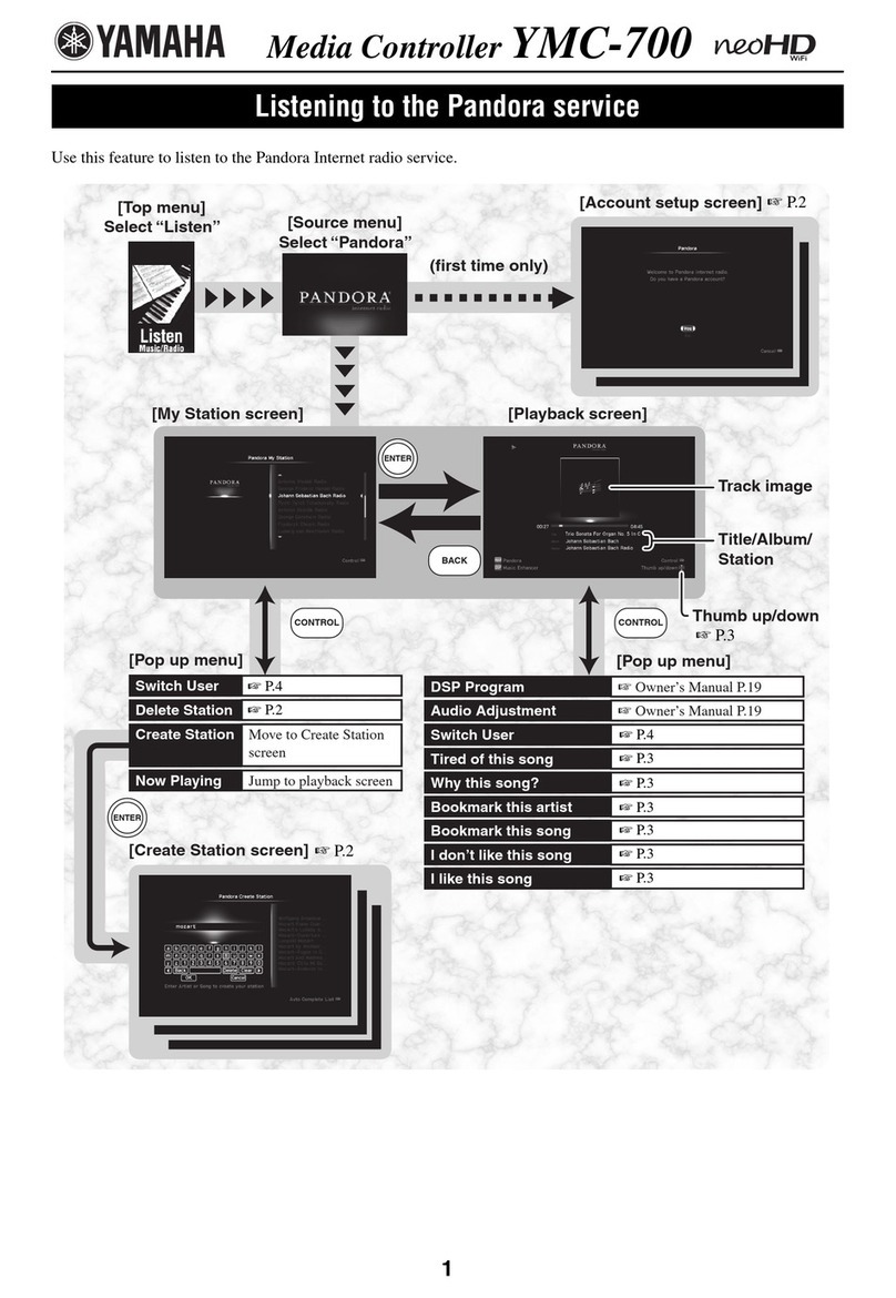
Yamaha neoHD YMC-700 User manual

Yamaha
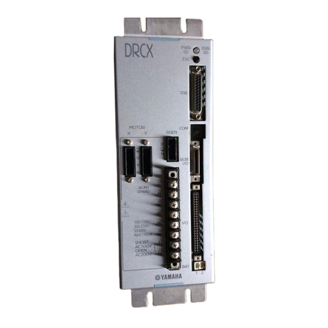
Yamaha DRCX User manual

Yamaha
Yamaha RCX240 User manual

Yamaha
Yamaha RCX340 User manual

Yamaha
Yamaha TS-P User manual

Yamaha
Yamaha SRCP User manual

Yamaha
Yamaha MCX-10 User manual

Yamaha
Yamaha disklavier DKC-850 Parts list manual

Yamaha
Yamaha C20A User manual

Yamaha
Yamaha SRCP30 User manual

Yamaha
Yamaha Nexo NXAMP4X4 User manual

Yamaha
Yamaha CEmarking RCX221 User manual

Yamaha
Yamaha G10 User manual

Yamaha
Yamaha MJC8 User manual
Yamaha
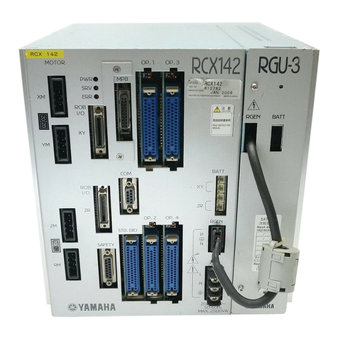
Yamaha RCX40 User manual
Yamaha
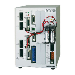
Yamaha ENSPIRE Controller User manual

Yamaha
Yamaha MJC8 User manual

Yamaha
Yamaha disklavier DKC-850 User manual
Yamaha
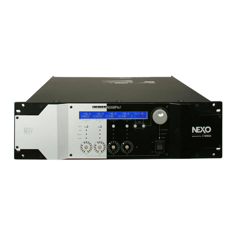
Yamaha MLC-200 User manual

Yamaha
Yamaha Mark IV User manual