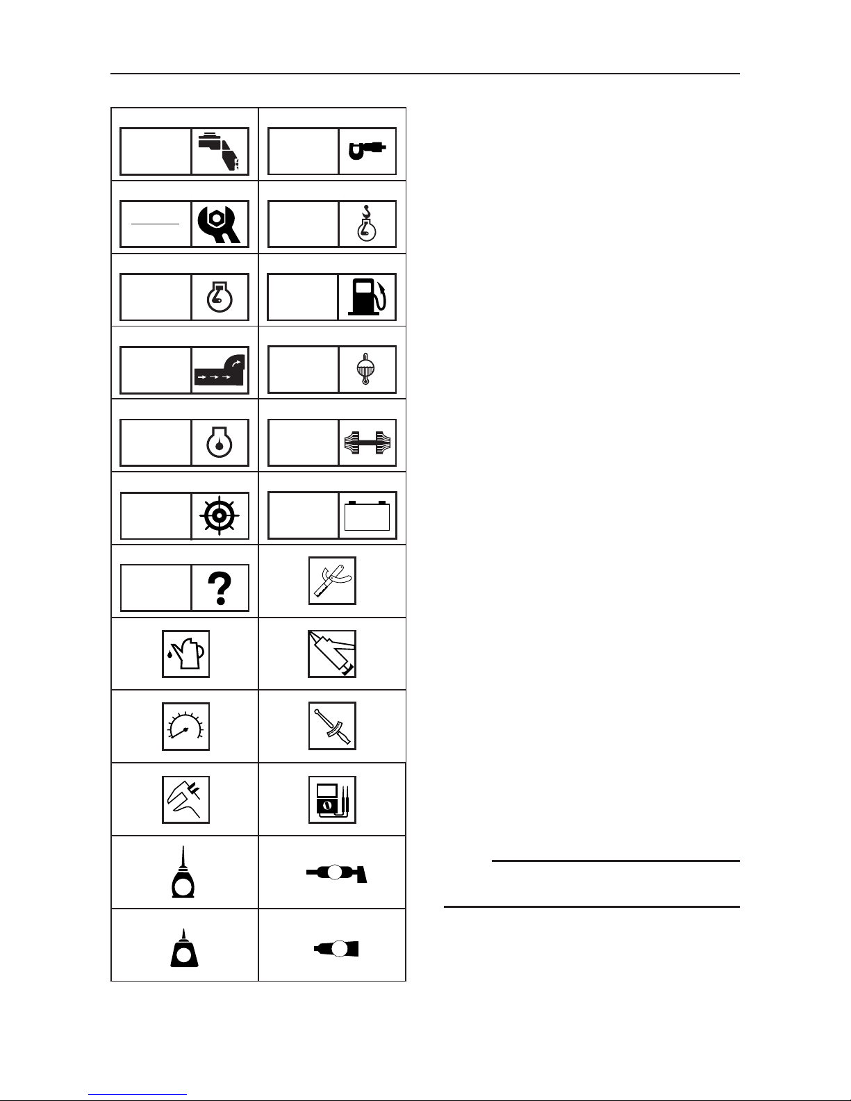
Yamaha ME422STI User manual

ME422STI ENGINE SERVICE MANUAL
300902-
ME422STI
N60-28197-ZH-11
ENGINE
SERVICE MANUAL
070026
PrintedinJapan
Nov.2005-0.5×1
YAMAHA MOTOR CO., LTD.
(ME422STI)
(E)
Printed on recycled paper
E

NOTICE
This manual has been prepared by Yamaha primarily for use by Yamaha dealers and
their trained mechanics when performing maintenance procedures and repairs to
Yamaha equipment. It has been written to suit the needs of persons who have a
basic understanding of the mechanical and electrical concepts and procedures
inherent in the work, for without such knowledge attempted repairs or service to the
equipment could render it unsafe or unfit for use.
Because Yamaha has a policy of continuously improving its products, models may
differ in detail from the descriptions and illustrations given in this publication. Use
only the latest edition of this manual. Authorized Yamaha dealers are notified
periodically of modifications and significant changes in specifications and
procedures, and these are incorporated in successive editions of this manual.
ME422STI
ENGINE SERVICE MANUAL
© 2005 Yamaha Motor Co., Ltd.
1st Edition, November, 2005
All rights reserved. Any reprinting or
unauthorized use without the written
permission of Yamaha Motor Co., Ltd. is
expressly prohibited.
Printed in Japan

HOW TO USE THIS MANUAL
MANUAL FORMAT
This manual provides the mechanic with descriptions of the operations of disassembly, repair,
assembly and check, each of which is presented in a sequential, step-by-step procedure.
To assist you in finding your way around this manual, the section title and major heading is
given at the head of each page.
A table of contents is provided on the first page of each section.
ILLUSTRATIONS
Some illustrations in this manual may differ from the model you have. This is because a proce-
dure described may relate to several models, though only one is illustrated. (The name of the
model described will be mentioned in the description).
To help you identify components and understand the correct procedures of disassembly and
assembly, exploded diagrams are provided. Steps in the procedure are numbered: 1), 2), 3).
Parts shown in the illustrations are identified as: 1, 2, 3.
REFERENCES
These have been kept to a minimum. References to other sections of the manual include the
relevant page number.

¡¡
¡¡
¡WARNING
Failure to follow WARNING instructions could result in severe injury or death to the marine
vehicle operator, a bystander, or a person checking or repairing the Stern Drive.
CAUTION:
A CAUTION indicates special precautions that must be taken to avoid damage to the Sterm
Drive.
NOTE:
A NOTE provides key information to make procedures easier or clearer.
INPORTANT INFORMATION
In this Service Manual particularly important information is distinguished in the following ways.
⁄The safety Alert Symbol means ATTENTION! BECOME ALERT! YOUR SAFETY IS INVOLVED!

CONSTRUCTION OF THIS MANUAL
This manual consists of chapters for the main categories of subjects. (See “Symbols” on the
next page.)
1st title 1: This is a chapter with its symbol on the upper right of each page.
2nd title 2: This title appears on the top of the each page, to the left of the chapter symbol.
3rd title 3: This title appears only in the chapter “Periodic check and adjustment”.
All the procedures in this manual are organized in a sequential, step-by-step order. The infor-
mation has been compiled to provide the mechanic with an easy-to-read, handy reference that
contains comprehensive explanations of all disassembly, check, repair, and assembly proce-
dures.
Important procedures including removing, checking, and assembling steps 4are explained in
detail.
IMPORTANT FEATURES
¡Important engine data and information about special tools framed in a box together with
an illustrative symbol 5.
¡A circled numeral 6indicates a part name. A circled lower case letter indicates data or an
alignment mark 7. Illustrations are sometimes labeled with an upper case letter 8.
¡An arrow 9indicates the course of action required to remedy the started condition of a
component.
EXPLODED DIAGRAM
Each chapter begins with exploded diagrams which facilitate correct disassembly and assem-
bly.

SYMBOLS
Symbols 1to Aare designed as thumb-tabs
and indicate the content of a chapter.
1General information
2Specifications
3Periodic check and adjustment
4Engine removal and installation
5Engine
6Fuel system
7Exhaust system
8Cooling system
9Lubrication system
0Turbocharger
APower steering system
BElectrical system
CTroubleshooting
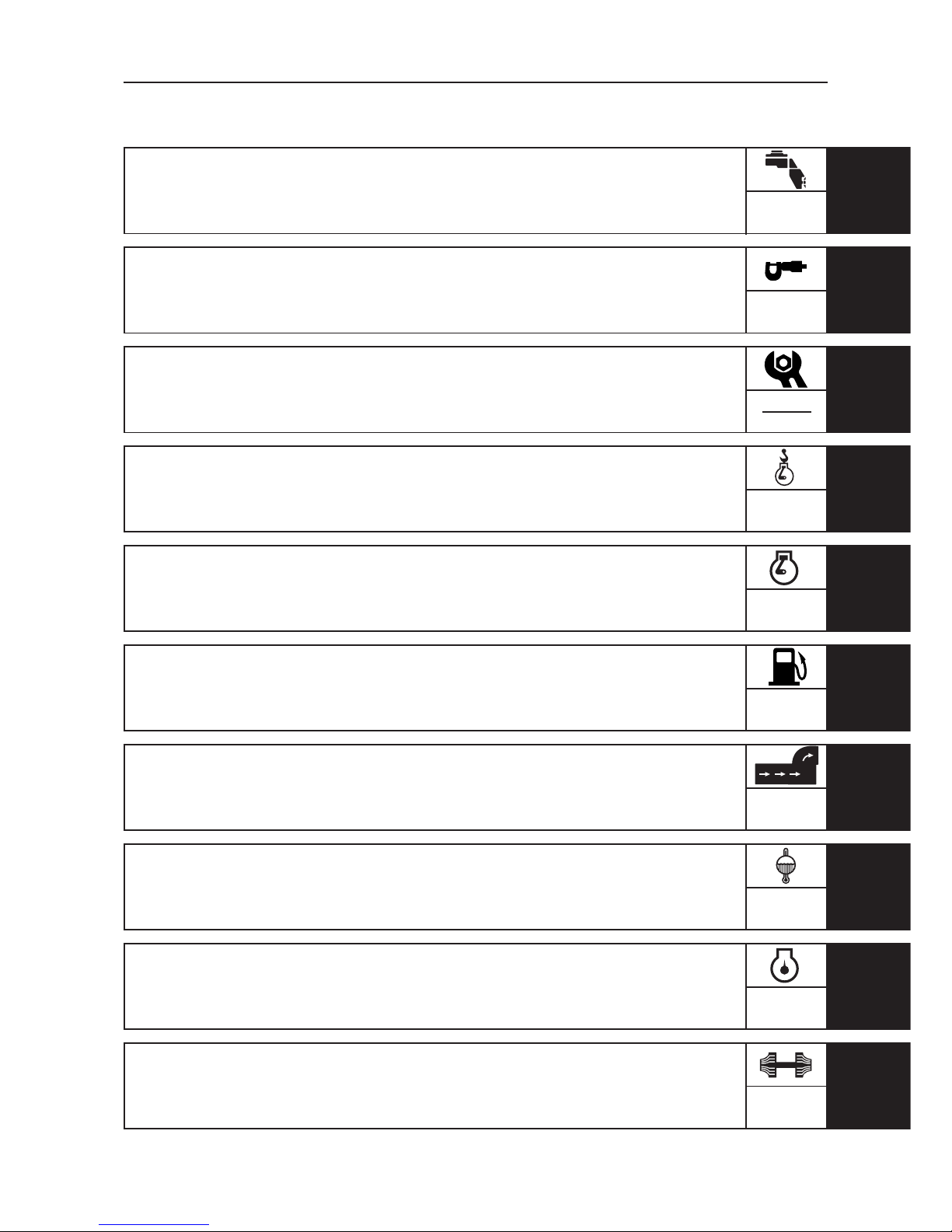
Symbols Dto Jindicate specific data:
DSpecial tool
ERecommended fuel
FLubricant
GEngine speed
HTightening torque
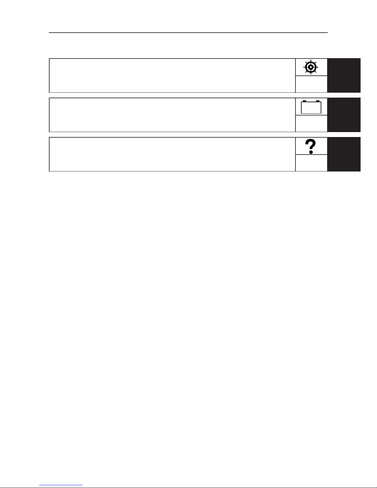
ISpecified value, service, limit
JResistance (Ω), Voltage (V), Electric cur-
rent (A)
Symbols Kand Lin an exploded diagram
indicate grade of lubricant and location of
lubrication point:
KApply Yamaha gear-case lubricant
LApply water resistant grease (Yamaha
marine grease A, Yamaha marine grease)
Symbols Mand Nin an exploded diagram
indicate grade of sealing or locking agent,
and location of application point:
MApply LOCTITE®No. 243, 271, 572
NApply Three Bond®TB-1207B, 1322, 1324
NOTE:
Some of the above symbols may not appear
in this manual.
12
34
56
78
90
AB
CD
EF
GH
IJ
K
N
L
M
T.R
A
LT
LT
G
TB
GEN
INFO SPEC
CHK
ADJ
REM
INST
ENG
OVER FUEL
EXHT COOL
LUB TURB
STEER
ELEC –
+
TRBL

CONTENTS
GENERAL INFORMATION 1
GEN
INFO
SPECIFICATIONS 2SPEC
PERIODIC CHECK AND
ADJUSTMENT 3
CHK
ADJ
ENGINE REMOVAL AND
INSTALLATION 4
REM
INST
ENGINE OVERHAUL 5
ENG
OVER
FUEL SYSTEM 6FUEL
EXHAUST SYSTEM 7EXHT
COOLING SYSTEM 8COOL
LUBRICATION SYSTEM 9
LUB
TURBOCHARGER
10
TURB


INDEX
POWER STEERING SYSTEM
11
STEER
ELECTRICAL SYSTEM
12
ELEC
TROUBLESHOOTING
13
TRBL
SHTG
–
+


E
CHAPTER 1
GENERAL INFORMATION
ENGINE IDENTIFICATION ...................................................................................................... 1-1
PROPELLER AND ENGINE ROTATION .................................................................................. 1-1
SAFETY WHILE WORKING .................................................................................................... 1-2
Prepare for Emergencies ................................................................................................... 1-2
Handle Fuel Safety ............................................................................................................. 1-2
Prevent Battery Explosion ................................................................................................. 1-2
Wear Protective Clothing .................................................................................................. 1-2
Keep Work Area Clean ....................................................................................................... 1-3
Operate Stern Drive Safely ............................................................................................... 1-3
PRE-DELIVERY CHECK ........................................................................................................... 1-4
Check Engine Alignment ................................................................................................... 1-4
Check Drive Belts ...............................................................................................................1-4
Check Engine Oil ................................................................................................................1-4
Check Fuel System ............................................................................................................ 1-4
Check Engine Exterior ....................................................................................................... 1-4
Check Battery and Electrical Connections ....................................................................... 1-4
Check Remote Control Operation ..................................................................................... 1-4
Perform Test Run ............................................................................................................... 1-5
OFF-SEASON STORAGE ........................................................................................................ 1-5
Engine ................................................................................................................................. 1-5
Drain Cooling System ....................................................................................................... 1-7
Preparation After Storage ................................................................................................. 1-8
CHECKS BEFORE LAUNCHING AND STARTING THE ENGINE .......................................... 1-9
INTERNATIONAL SYSTEM OF UNITS [SI] ......................................................................... 1-11
Description of “SI” Units in This Service Manual ......................................................... 1-11
SPECIAL TOOLS ...................................................................................................................1-12
OTHER EQUIPMENT TOOLS ............................................................................................... 1-16
GEN
INFO
1

1-1
GEN
INFO E
ENGINE IDENTIFICATION /
PROPELLER AND ENGINE ROTATION
ENGINE IDENTIFICATION
When servicing, inspecting or ordering the
spare part of the engine or marine gear, check
the identification number as follows.
NOTE:
Because of the identification number plate
is sticked with special method, the engine
number and the serial number will be invalid
when removed.
The model and serial number plate is located
on the header tank.
The different models can be identified by
checking the model and serial number plate
and using the following table.
PROPELLER AND ENGINE ROTA-
TION
DO NOT rely on propeller rotation to be in
the same direction as engine rotation.
Engine rotation is determined by looking at
the flywheel end of the engine.
The Yamaha engines covered in this manual
rotate counterclockwise (to the left) as viewed
from the flywheel.
MODEL PREFIX
VARIATION* SERIAL NO.
ABC D
ME422STIP1
N611 SP ******
N612 P ******
ME422STIP2
N601 SP ******
N602 P ******

1-2
GEN
INFO E
SAFETY WHILE WORKING
Prepare for Emergencies
Be prepared for possible fires.
Keep the following items handy:
¡First Aid Kit
¡Fire Extinguisher
¡Emergency Phone Numbers
Handle Fuel Safety
Use care when handling fuel; it is highly flam-
mable. DO NOT smoke or have open flames
or sparks nearby when handling fuel.
Always clean up spilled fuel oil and dispose
of cleaning materials properly.
Wear Protective Clothing
Wear safety equipment whenever necessary:
¡Safety glasses or goggles
¡Earmuffs or earplugs
¡Safety shoes
¡Gloves
¡Respiratory protection
Avoid wearing loose clothing and jewelry.
Prevent Battery Explosion
Batteries produce explosive gases. Keep
sparks and flames away from batteries.
Check battery electrolyte level using a flash-
light.
Never check battery state of charge by con-
necting the battery posts with a conductor.
Use a voltmeter or hydrometer. Always dis-
connect the negative (–) cable first and re-
connect it last.
DO NOT charge a battery if the battery is fro-
zen. Allow the battery to warm up first.
Charge the battery in a well-ventilated area.
Battery electrolyte is poisonous and danger-
ous. It contains sulfuric acid and causes se-
vere burns. Avoid contact with skin, eyes or
clothing. If electrolyte gets in the eyes, flush
with water for 15 minutes and get prompt
medical attention.

1-3
GEN
INFO E
SAFETY WHILE WORKING
Keep Work Area Clean
Properly ventilate your work area.
Keep the shop bench and floor clean and dry.
Cover all parts and part opening when they
are not being worked on, to prevent foreign
materials from entering and damaging the
engine.
Cleaning and protection of machined sur-
faces and friction areas are part of the repair
procedure; this is considered standard shop
practice.
Operate Stern Drive Safely
Remove the propeller.
DO NOT operate engine without cooling
water supplied to the water inlet ports on the
drive unit.

1-4
GEN
INFO E
PRE-DELIVERY CHECK
PRE-DELIVERY CHECK
Perform the following checks to prepare the
engine for delivery to the customer.
Check Engine Alignment
¡Use an engine alignment tool to check
engine alignment. Make any adjust-
ments as necessary. Refer to “Engine
Installation” on page 4-5.
¡Make sure all engine mounting hardware
1is tight.
Check Drive Belts
¡Check the tension of the alternator and
circulation pump belts 2.
Check Engine Oil
¡Make sure break-in oil is at the proper
level 3.
Check Fuel System
¡Make sure all fuel lines and hoses are
connected and do not leak.
¡If water separator warning light comes
on, drain the water from the water sepa-
rator 4.
Check Engine Exterior
¡Touch-up any painted surfaces with
matching paint.
¡Replace any parts damaged in shipping.
Check Battery and Electrical Connec-
tions
¡Check the battery fluid level.
¡Check if the battery is fully charged.
¡Verify that the battery is securely at-
tached to the boat.
¡Check that the battery cables are cor-
rectly and securely connected.
¡Check all wire harness connections for
proper contact and tightness.
Check Remote Control Operation
¡Make sure the engine can be controlled
properly with the remote control.

1-5
GEN
INFO E
PRE-DELIVERY CHECK / OFF-SEASON STORAGE
Perform Test Run
¡Be sure gear shifting and steering is
smooth.
¡Check for leaks in the transom.
OFF-SEASON STORAGE
If the boat is kept unused for a long period,
internal parts of the engine or drive unit
might rust through of lack of lubrication and
protection. If the boat is stored in below-freez-
ing temperatures, seawater inside the sea-
water cooling system may freeze, causing
extensive engine damage.
Therefore precautions must be taken, to pre-
vent rusting and freezing.
Engine
When carrying out the following storage
preparation, be sure to flush the cooling sys-
tem thoroughly. Refer to “Cooling System
Flushing” on page 3-42.
1) Warm up the engine to normal operat-
ing temperature.
2) Stop the engine, drain the engine oil and
replace the oil filter 1.
¡¡
¡¡
¡WARNING
When working in the engine compartment,
run the bilge blower if the boat has one. If
not, insure that the engine compartment is
sufficiently ventilated.
CAUTION:
¡¡
¡¡
¡While running the engine, be sure to use
flushing gear or a water tank to provide
cooling water to the cooling system. Also
keep the engine speed at idling.
¡¡
¡¡
¡While operating the engine, be sure the
water temperature and oil temperature
are kept within the proper range to pre-
vent engine overheating and subsequent
damage.

1-6
GEN
INFO E
OFF-SEASON STORAGE E
3) Tighten the drain bolt to the specified
torque, and add the indicated amount of
new engine oil. (Refer to “Engine Oil
Level Check” on page 3-7.)
4) Start the engine and run it at a speed be-
tween 1000 – 1200 r/min. Be sure no oil
leaks from the oil filter joint.
5) Stop the engine and check with an oil
level gauge whether the oil is at the
specified level. (Refer to “Engine Oil
Level Check” on page 3-7.)
6) Turn the fuel cock on the fuel tank side
to “OFF”.
7) Install a new filter 2and filter cover. (Re-
fer to “Fuel Filter Replacement” on page
3-31.)
8) Drain all diesel fuel from the fuel tank,
or alternatively, fill the tank completely.
9) Clean the oil separator 3and blow-by
hose 4, then reinstall it securely.
10) After turning off the main switch, turn
the battery switch “OFF” (if the boat is
equipped with one), or disconnect the
battery cables from the terminals.
12) Lubricate the shift and throttle cables and
the linking mechanisms.
CAUTION:
If the battery is stored without being prop-
erly charged, there is a danger that it will
freeze. A stored battery should be checked
once a month and appropriate maintenance
should be performed.
11) Remove the battery and clean it. Add dis-
tilled water to the specified level and re-
charge the battery. Apply petroleum-
based grease to the terminals.
Store the battery in a cool, dry place.
CAUTION:
¡¡
¡¡
¡DO NOT turn off the battery switch while
the ignition switch is still on.
This could damage the voltage regulator.
¡¡
¡¡
¡When disconnecting the battery cables,
start with the (–) terminal.
3
4

1-7
GEN
INFO E
OFF-SEASON STORAGE
Drain Cooling System
To pr o t e c t t he cooling system from r ust and
damage from freezing, drain coolant from the
cooling system completely.
1) Remove the drain cocks, plugs and hoses
located as shown, and drain the coolant.
Coolant:
¡Drain plug 1on the port side of the
cylinder block
¡Drain plug 2on the turbo charger
housing
¡Hose 3connected to the heat ex-
changer
Seawater:
¡Drain cock 4on the heat exchanger
¡Seawater hose 5
2) Loosen clamps of the hoses in the loca-
tion described below then disconnected
the hoses.
¡Heat exchanger 6
¡Seawater pump 7
¡Seawater strainer 8
NOTE:
¡When draining coolant, cover all electri-
cal parts and accessories with a plastic
cover to prevent them from getting wet.
¡After draining the coolant, remove the
drain bolt on the bottom of the boat to
drain any coolant that has collected in the
bilge (provided the boat is on land). If the
boat is in the water, use a bilge pump in-
stead. After draining, rinse thoroughly
with clean water and dry.
¡If possible, lift the front of the engine
slightly, so that the coolant water drains
completely from the cylinder block.
CAUTION:
DO NOT store the engine with water left in
the cooling system.
NOTE:
¡After removing the hoses, if necessary,
drain any remaining coolant and seawa-
ter by bending, lifting or shaking the hose.
¡If sand or other dirt clogs up a drain hole,
use a needle or similar tool to free it.

1-8
GEN
INFO E
OFF-SEASON STORAGE
3) When all coolant and seawater has been
drained, apply a sealant to the drain
plugs and tighten them to the specified
torque.
4) Check that the hoses are neither cracked
nor damaged and re-connect them. Be
sure to tighten the hose clamps securely.
Preparation After Storage
To prepa re an eng ine afte r it has bee n stored
for a long time, perform the checks and the
maintenance described below, as well as
those described in “CHECKS BEFORE
LAUNCHING AND STARTING THE ENGINE”
(Refer to “CHECKS BEFORE LAUNCHING
AND STARTING THE ENGINE”on page 1-9.)
1) Tighten the drain plugs of the water cool-
ing system. Check the condition of the
cooling system hoses. Check if the hose
clamps are in good condition and tight-
ened securely.
2) Check the condition of the drive belts on
the alternator 1and circulation pump
2. Adjust the tension of the drive belts
to the specified deflection.
3) Check that the engine mount, drive unit,
and power trim cylinder are securely at-
tached, that the steering and throttle
cables are properly connected, and that
the electrical system connectors are
firmly attached.
4) After engine check is completed, install
and securely connect a fully charged bat-
tery.

1-9
GEN
INFO E
OFF-SEASON STORAGE / CHECKS BEFORE
LAUNCHING AND STARTING THE ENGINE
5) Check all the items listed under “CHECKS
BEFORE LAUNCHING AND STARTING
THE ENGINE”, and perform any neces-
sary maintenance.
6) Test run the engine on land or in the
water and make sure there are no prob-
lems of any kind.
CHECKS BEFORE LAUNCHING
AND STARTING THE ENGINE
The following items should be checked be-
fore starting the engine.
1) Check that no fuel is leaking from a fuel
line or connection. Also, verify that no
oil or fuel has leaked into the engine com-
partment. (Refer to “FUEL LINE CHECK”
on page 3-26.)
2) Check that the drain plugs of the cooling
system are securely tightened, and that
no water leakings into the bilge.
3) Check the battery fluid level (Refer to
“Battery Check”on page 3-43.)
Check that the battery terminals are not
loose, corroded, or damaged. Securely
fasten the battery to the boat.
¡¡
¡¡
¡WARNING
Explosive battery fumes may collect in the
engine compartment. Before starting the
engine, ventilate the engine compartment.
If the boat has a bilge blower, let it run for at
least 3 minutes. If not, open the hatch and
ventilate for at least 5 minutes.
CAUTION:
¡¡
¡¡
¡Make sure all periodic check, mainte-
nance, and periodic replacement of parts
have been performed. (Refer to “PERI-
ODIC CHECK AND ADJUSTMENT” on
page CHAPTER 3.)
¡¡
¡¡
¡From time to time, check the water in-
take area of the drive unit. Make sure the
opening is not clogged with seaweed or
anything else.
Table of contents
Other Yamaha Outboard Motor manuals