■Audio Section / オーディオ部
Rated Output Power (Power Amp. Section) /
定格出力(パワーアンプ部)
(1 kHz, 0.9 % THD)
– 1 channel driven –
R, T, K, A, B, G, F, L, H models (8 ohms)
FRONT L/R ................................................................ 130 W/ch
CENTER .......................................................................... 130 W
SURROUND L/R ........................................................ 130 W/ch
SURROUND BACK L/R ............................................. 130 W/ch
B, G, F models (4 ohms)
FRONT L/R ................................................................ 160 W/ch
J model (6 ohms)
FRONT L/R ................................................................ 130 W/ch
CENTER .......................................................................... 130 W
SURROUND L/R ........................................................ 130 W/ch
SURROUND BACK L/R ............................................. 130 W/ch
– 2 channel driven simultaneously –
R, T, K, A, B, G, F, L, H models (8 ohms)
FRONT L/R .......................................................110 W + 110 W
CENTER .......................................................................... 110 W
SURROUND L/R ...............................................110 W + 110 W
SURROUND BACK L/R ....................................110 W + 110 W
J model (6 ohms)
FRONT L/R .......................................................110 W + 110 W
(20 Hz to 20 kHz, 0.09 % THD)
– 2 channel driven simultaneously –
R, T, K, A, B, G, F, L, H models (8 ohms)
FRONT L/R ...........................................................95 W + 95 W
J model (6 ohms)
FRONT L/R ...........................................................95 W + 95 W
Maximum Effective Output Power / 実用最大出力 (JEITA)
(1 channel driven / 1 kHz, 10 % THD) [R, T, L, H, J models]
R, T, L, H models (8 ohms)
FRONT L/R ...................................................................... 160 W/ch
CENTER ............................................................................... 160 W
SURROUND L/R .............................................................. 160 W/ch
SURROUND BACK L/R ................................................... 160 W/ch
J model (6 ohms)
FRONT L/R ...................................................................... 160 W/ch
CENTER ............................................................................... 160 W
SURROUND L/R .............................................................. 160 W/ch
SURROUND BACK L/R ................................................... 160 W/ch
Dynamic Power Per Channel / ダイナミックパワー (IHF)
FRONT L/R (1 channel driven)
R, T, K, A, B, G, F, L, H models
(8 / 6 / 4 / 2 ohms) .................................. 140 / 180 / 210 / 250 W
J model
(6 / 4 / 2 ohms) ................................................ 150 / 180 / 220 W
Damping Factor / ダンピングファクタ (20 Hz to 20 kHz, 8 ohms)
FRONT L/R to SPEAKER-A ............................................ 100 or more
Input Sensitivity/Input Impedance / 入力感度/入力インピーダンス
(1 kHz, 100 W/8 ohms)
PHONO (MM) .................................................... 3.5 mV / 47 k-ohms
AV5 etc. ............................................................ 200 mV / 47 k-ohms
Maximum Input Signal / 最大許容入力 (1 kHz)
PHONO (MM) (0.1 % THD) ..................................................... 60 mV
AV5 etc. (Effect ON) (0.5 % THD) ......................................... 230 mV
■SPECIFICATIONS /
参考仕様
Output Level/Output Impedance / 出力電圧/出力インピーダンス
REC OUT ......................................................... 200 mV / 1.2 k-ohms
SUBWOOFER (2 channel stereo and FRONT SP: small)
.............................................................................. 1 V / 1.2 k-ohms
R, T, K, A, B, G, F, L, H models
ZONE2 OUT .................................................. 200 mV / 1.2 k-ohms
Headphone Jack Rated Output/Output Impedance /
ヘッドホン出力/出力インピーダンス
AV5 etc. input (1 kHz, 50 mV, 8 ohms) .............. 100 mV / 560 ohms
Frequency Response / 再生周波数帯域
AV5 etc., FRONT (10 Hz to 100 kHz) ...................................0 / -3 dB
RIAA Equalization Deviation / RIAA 偏差
PHONO (MM) ................................................................... 0 ±0.5 dB
Total Harmonic Distortion / 全高調波歪率 (20 Hz to 20 kHz)
PHONO (MM) to REC OUT (1 V) ................................0.02 % or less
AV5 etc. (PURE DIRECT) to FRONT SP OUT (50 W)
R, T, K, A, B, G, F, L, H models (8 ohms) .................0.06 % or less
J model (6 ohms) .....................................................0.06 % or less
Signal to Noise Ratio / 信号対雑音比 (IHF-A network)
PHONO (MM) to REC OUT
R, T, K, A, B, G, F, L, H models (Input shorted 5 mV)
............................................................................. 81 dB or more
J model (Input shorted 2.5 mV)
.................................................................................80 % or less
AV5, etc. (PURE DIRECT) to SP OUT (Input shorted 250 mV)
.............................................................................. 100 dB or more
Residual Noise / 残留ノイズ (IHF-A Network)
FRONT L/R to SP OUT ................................................150 μV or less
Channel Separation / チャンネルセパレーション (1 kHz / 10 kHz)
PHONO (Input shorted)
...................................................... 60 dB or more / 55 dB or more
AV5, etc. (Input 5.1 k-ohms shorted)
...................................................... 60 dB or more / 45 dB or more
Volume Control / 可変範囲/ステップ
......................................... MUTE / -80 dB to +16.5 dB / 0.5 dB step
Tone Control Characteristics / トーンコントロール特性
Bass
Boost/Cut ........................................ ±6 dB / 0.5 dB step, at 50 Hz
Turnover frequency .............................................................350 Hz
Treble
Boost/Cut .......................................±6 dB / 0.5 dB step, at 20 kHz
Turnover frequency ............................................................ 3.5 kHz
Filter Characteristics / フィルタ特性
FRONT, CENTER, SURROUND, SURROUND BACK small (H.P.F.)
.................... fc=40/60/80/90/100/110/120/160/200 Hz, 12 dB/oct.
SUBWOOFER small (L.P.F.)
.................... fc=40/60/80/90/100/110/120/160/200 Hz, 24 dB/oct.
Optical Jack, Coaxial Jack Support Fs /
Optical 端子、Coaxial 端子対応 Fs
............................................................................... 32 kHz to 96 kHz
7
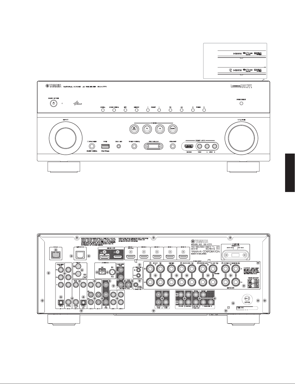
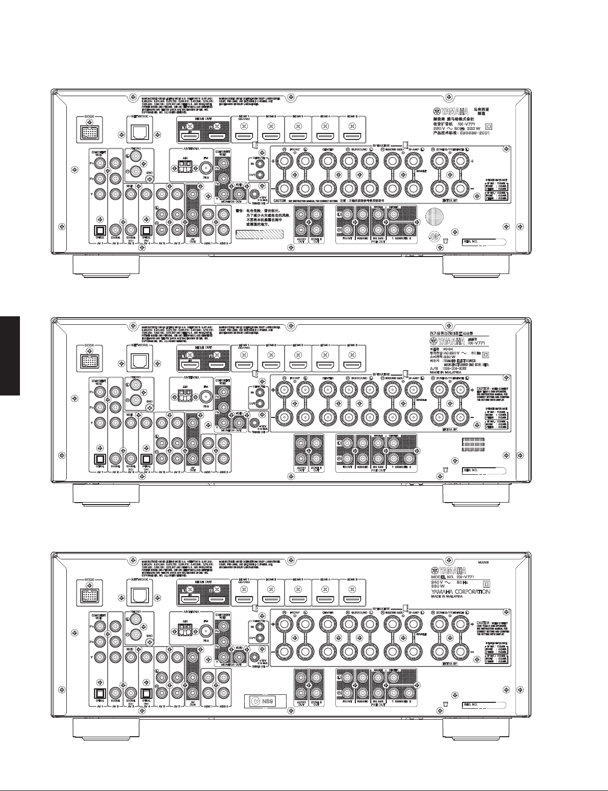
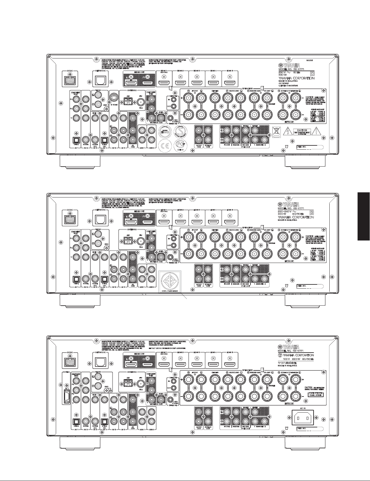
RX-V771
RX-V771