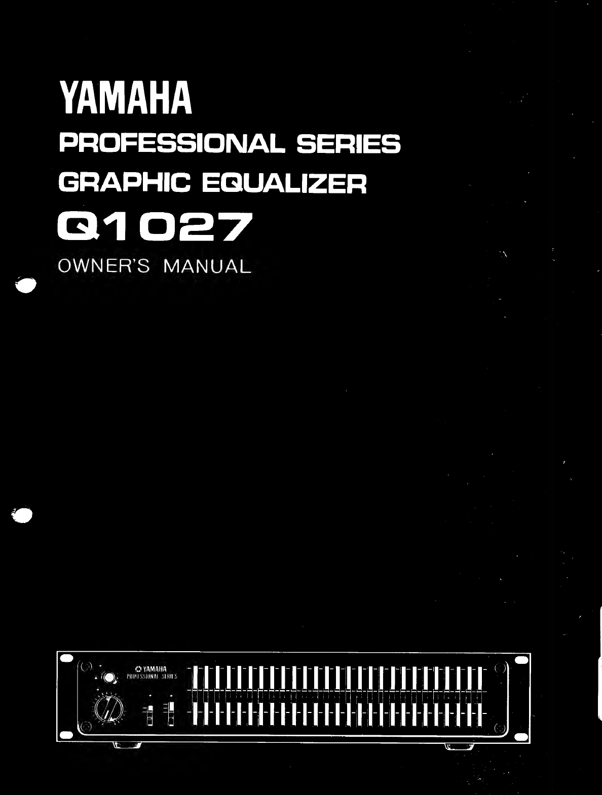
Yamaha PROFESSIONAL Q1027 User manual

YAMAHA
PROFESSIONAL
SERIES
GRAPHIC
EQUALIZER
Q1027
OWNER’S
MANUAL
o:
MR
nu
m
Er
id
M
ΠΝ

FEATURES
/
CAUTION
The
Q1027
is
a
professional-grade
27-band
graphic
equalizer
that
offers
top-quality
performance,
features,
reliability
and
durability.
It
is
perfectly
suited
to
a
wide
range
of
professional
applications
including
concert
sound
reinforcement
and
studio
recording.
Please
be
sure
to
read
this
operation
manual
carefully
in
order
to
make
the
most
of
your
Q1027's
extensive
perform-
ance
capabilities.
FEATURES
ΦΑΙ!
inputs
and
outputs
feature
Phase
Switches,
Ground
Switches
and
cannon
connectors,
Rack-mountable
configuration.
Rugged
to
withstand
the
rigors
of
profes-
sional
use.
Human-engineered
control
layout
for
fast,
error-free
operation.
Elegant
styling.
Exceptionally
high
S/N
ratio
and
low
distortion.
@27
1/3-octave
equalizer
bands
provide
extremely
fine
control
capability.
Unique
“L”
integrated
circuit
construction
effectively
minimizes
inductive
noise
pick-
up
maintaining
excellent
signal-to-noise
ratio
and
low
distortion.
@Equalizer
bypass
switch,
40/80
Hz
high-pass
filter
selector,
accurate
input
attenuator
and
peak
level
indica-
tor
all
add
up
to
more
convenient,
more
precise
sound
control.
Removable
security
cover
prevents
accidental
alteration
of
settings
in
studio
and
sound
reinforcement
applications.
Designed
for
optimum
“in-use”
flexibility
and
performance.
CONTENTS
ΕΕΑΤΥΒΕΒ/ΘΑΌΤΙΟΝ..................
2
FRONT
PANEL
OPERATION
.............
3
CONNECTION/BLOCK
DIAGRAM..........
4
REAR
PANEL
OPERATION
..............
5
ΕΩΙΑΙΙΖΙΝα........................
6
MOUNTING
THE
SECURITY
COVER/SPECIFICATIONS
...............
7
CAUTION
@Locate
the
Q1027
out
of
the
direct
rays
of
the
sun,
avoiding
locations
subject
to
vibration
and
excessive
dust,
heat,
cold
or
moisture.
@When
displacing
the
instruments,
be
sure
to
disconnect
the
power
supply
cord
and
every
connecting
cord
to
prevent
their
breakage
and
short,
eDo
not
attempt
to
clean
any
accumulations
of
dirt
with
chemical
solvents
(such
as
alcohol
or
benzene).
Wipe
only
with
a
clean
completely
dry
cloth.
€
Keep
this
manual
in
a
safe
place
for
future
reference,
and
refer
to
it
frequently
until
you
are
fully
familiar
with
your
Q1027.
e
This
model
is
designed
to
be
mounted
on
19"
standard
rack.
e
Voltage
Selector
switch
on
the
rear
of
the
O1027
must
be
set
for
your
local
mains
voltage
BEFORE
plugging
in
the
AC
main
supply.
Voltages
are
110-130
or
220-240AC,
50/60Hz.
U.S.
and
Canadian
models
are
not
provided
with
the
voltage
selector.

FRONT
PANEL
OPERATION
ΕΠ
RENI
@
POWER
switch
When
this
switch
is
depressed
to
the
ON
position,
the
power
is
supplied
to
the
equalizer
and
the
indicator
lights.
Depress
the
switch
again
to
set
it
to
the
OFF
position,
*
Between
three
and
five
seconds
after
the
switch
has
been
set
to
ON,
the
muting
circuit
is
activated
in
order
to
suppress
the
pop
noise,
produced
when
the
power
is
initially
supplied,
and
there
are
no
output
signals.
O
Equalizer
section
Available
in
this
section
are
the
control
knobs
which
are
used
to
increase
or
reduce
the
center
frequency
level
of
the
frequencies
in
the
audible
band
which
is
divided
into
27
parts.
Based
on
a
reference
value
of
O
dB,
the
level
may
be
varied
up
to
a
maximum
of
+12
dB.
To
set
the
level,
align
the
red
line
of
the
knob
with
the
setting
scale.
Red
line
E
El
E
El
El == EJ
E
RESPONSE
(48)
RESPONSE
(dB)
ΤΗΕ:
FREQUENCY
(Hz)
O
PEAK
indicator
This
lights
when
the
output
level
exceeds
+21
dB
and
it
warns
that
the
output
level
is
excessively
high.
OINPUT
Attenuator
This
is
used
to
adjust
the
input
level.
When
rotated
in
the
counterclockwise
direction,
it is
possible
to
attenu-
ate
the
level
in
1
dB
steps
down
to
—20
dB.
At
the
co
position,
the
input
signals
are
cut
off
entirely
and
there
is
no
sound,
When
the
overall
level
has
risen
due
to
equalizing,
take
steps
to
turn
down
the
input
level
by
a
value
equivalent
to
the
rise
in
the
level
and
eliminate
the
difference
in
level
caused
by
the
presence
or
absence
of
equalizing.
*
The
attenuator
does
not
work
when
the
EQ
switch
is
set
to
the
OUT
position.
O
EO
(equalizer
bypass)
switch
This
switch
isolates
the
equalizer
section
and
passes
the
input
signals
to
the
output.
When
the
knob
is
set
to
IN,
the
indicator
light
to
indicate
that
the
equalizer
section
is
now
working.
When
it is
set
to
OUT,
the
indicator
goes
off,
and
the
input
signals
bypass
the
INPUT
ATT
contro!
and
the
equalizer
section,
and
they
are
sent
straight
to
the
output.
In
cases
like
this,
the
Q1027
functions
as
a
buffer
amplifier,
and
the
EQ
switch
is
used
to
compare
the
sound
quality
with
and
without
equalizing.
INPUT
T
oyr
OUTPUT
QHPF
(high-pass
filter)
switch
This
filter
has
a
slope
response
of
18
dB/oct
and
its
switch
allows
selection
between
a
cutoff
frequency
of
40Hz
and
80Hz.
At
the
"40"
position,
signals
with
a
frequency
of
less
than
40Hz
are
attenuated,
and
it
is
possible
to
suppress
the
low-frequency
standing
waves
(low-frequency
resonance)
produced
in
studios
and
small
rooms,
to
eliminate
the
muddiness
in
the
low
range
and
to
obtain
a
clear-cut
sound,
At
the
'"'80"
position,
signals
with
a
frequency
of
less
than
80Hz
are
attenuated,
and
it
is
possible
to
reduce
the
"fuzziness''
of
vocal
microphones
and
the
hum
and
noise
of
electrical
musical
instruments,
etc.
The
indicator
light
when
the
switch
is
set
to
the
"40"
and
“80”
position.
FREQUENCY
RESPONSE
®—
Indicator

CONNECTION
BLOCK
DIAGRAM
CONNECTION
MIXER(PRE.
AMPLIFIER)
ΒΙΣΙΕΙΦΙΣΙΣ
SOURCE
SPEAKER
[
BLOCK
DIAGRAM
9
[A
era
ATT
[INPUT]
d
,
i-----
g-----Z
ET
40Hz
800Hz
Ι6ΚΗΣ
(se
>
L-
27
BANO
—
ON
o
OFF
PIN
1
GND
SW
OFF
o
FUSE
σ
ο
€)
LED

REAR
PANEL
OPERATION
|
O
YAMAHA
|
ΠΠ
SER
NO
|
PATENI
PENDING
@
OUTPUT
O
Cannon
socket
XLR-3-32
It
is
provided
with
a
Cannon
socket
for
balanced
output
The
Q1027
employs
a
3-pin
(pin
1
shielded
ground,
pin
applications
and
a
phone
jack
for
unbalanced
output
2
hot,
pin
3
cold)
socket
for
connection,
applications,
The
output
impedance
in
either
case
is
40
Compatible
plugs
include
the
Cannon
XLR-3-11C
and
ohms,
the
Switchcraft
A-3-F.
*
The
phone
jack
output
takes
priority
when
both
the
Cannon
socket
and
phone
jack
are
connected
@Cannon
socket
XLR-3-31
simultaneously.
Compatible
plugs
include
the
Cannon
XLR-3-12C
and
the
Switchcraft
A-3-M,
@
OUTPUT
PHASE
switch
This
switch
selects
the
phase
of
the
balanced
output.
Set
@
Phone
jacks
to
the
“N”
side
to
match
the
phases
of
the
input
and
These
employ
standard
plugs.
output
and
to
the
“R”
side
for
reverse
phase,
The
switch
is
used
for
phase
alignment
when
many
O
Fuse
components
have
been
connected
or
when
the
phase
Always
use
a
fuse
with
the
same
ratings
of
the
existing
changes
in
accordance
with
the
setting
position
of
the
one
for
replacement
purposes.
speaker
system.
*
The
phase
of
the
phone
jack
side
cannot
be
selected.
O
VOLTAGE
SELECTOR
(General
Models
Only)
Set
this
to
your
local
AC
mains
voltage.
Failure
to
do
so
©
INPUT
will
result
in
seriously
impaired
performance
or
even
It
is
provided
with
a
Cannon
socket
for
balanced
input
severe
damage.
applications
and
a
phone
jack
for
unbalanced
input
applications.
The
input
impedance
is
8
kiloohms
for
the
balanced
input
and
10
kiloohms
for
the
unbalanced
input.
*
The
phone
jack
input
takes
priority
when
both
the
Cannon
socket
and
phone
jack
are
connected
simultaneously,
OPIN
1
GND
switch
This
switch
sets
the
balanced
output
ground
line
(pin
1
shielded
ground)
to
ON
and
OFF.
Hum
or
noise
is
sometimes
caused
by
the
illumination
inside
the
hall
and
the
high-power
components
when
signal
cables
are
used
extendedly
or
when
they
are
used
in
a
certain
placement
to
connect
a
number
of
compo-
nents.
This
noise
can
sometimes
be
reduced
by
isolating
the
ground
line,
In
a
case
like
this,
use
this
switch.

EQUALIZING
This
model
divides
the
audible
frequency
40Hz—16kHz
by
1/3
octaves
into
27
portions
to
enable
extremely
intricate
compensation.
Equalizing
can
be
provided
from
the
twin
aspects
of
indoor
transmission
response
and
howl,
and
it is
possible
to
improve
the
sound
quality
at
the
audience
seats
by
making
the
indoor
transmission
response
flat,
and
also
tc
provide
a
sufficient
howl
respite
for
microphones
used
on
the
stage.
e
Equalizing
for
correct
indoor
response
The
frequency
response
curves
and
specifications
provided
with
speaker
units
and
systems
are
derived
from
measurements
taken
in
an
“anechoic
chamber”
(an
acoustically
"dead"
room
in
which
no
reflection
of
sound
takes
place).
When
used
in
a
real
listening
environment
such
as
a
hall
or
club,
however,
the
actual
percieved
response
is
highly
dependent
on
the
acoustic
properties
of
the
listening
area.
Hard
surfaces
such
as
windows,
wood
panelling
and
tile
floors
can
reflect
the
high
frequencies
causing
a
"tinny"
or
"ringing"
sound,
while
curtains,
chairs
and
even
people
can
absorb
high
frequencies
causing
a
"flat"
or
“muddy”
response.
It
is
therefore
essential
that
the
sound
reinforcement
system
be
properly
equalized
to
compensate
for
the
PINK
NOISE
GENERATOR
e
Equalizing
to
combat
howl
Depending
on
the
acoustics
of
a
hall
or
room,
howl
is
sometimes
heard
at
a
specific
frequency.
In
a
case
like
this,
howl
can
be
prevented
by
reducing
the
gain
only
for
that
frequency
where
the
howl
is
generated.
For
accurate
equalizing,
a
pink
noise
generator
and
a
real
time
analyzer
are
useful,
Set
the
microphone
on
the
stage,
connect
the
pink
noise
generator
to
the
auxiliary
input
of
the
PA
console
mixer
and
the
real
time
REAL
TIME
ANALYZER
PINK
NOISE
GENERATOR
specific
acoustic
conditions
in
the
area
where
it is
to
be
used.
In
order
to
improve
the
sound
quality
at
the
listening
position,
it
is
necessary
to
perform
equalizing
of
the
indoor
transmission
response.
For
this
kind
of
equalizing,
a
pink
noise
generator
and
a
real
time
analyzer
must
be
provided
as
measuring
instruments.
Connect
the
pink
noise
generator
to
the
PA
console
mixer
and
the
pink
noise
is
then
heard
through
the
speaker.
Use
the
real
time
analyzer
in
the
service
area
to
measure
this
noise
and
adjust
the
controls
on
the
graphic
equalizer
so
that
the
indicated
transmission
response
is
made
flat,
SPEAKER
REAL
TIME
ANALYZER
analyzer
to
the
auxiliary
output,
and
then
increase
the
gain.
Use
the
controls
on
the
graphic
equalizer
to
adjust
the
gain
of
the
frequency
where
the
howl
is
generated,
and
if
as
a
result
howl
is
generated
at
almost
every
frequency
when
the
gain
is
increased,
it
means
that
the
problem
of
the
howl
at
the
original
frequency
has
been
resolved.
SPEAKER
With
compensation
using
only
measuring
instruments,
the
sound
is
sometimes
found
to
be
lacking,
and
after
performing
equalizing
from
the
twin
aspects
of
the
indoor
transmission
response
and
howl,
check
the
sound
quality
and
level
balance
in
the
service
area
by
ear,
and
perform
overall
adjustment.

MOUNTING
THE
SECURITY
COVER
ΘΖ
SPECIFICATIONS
Mounting
the
security
cover
If
the
control
knobs
on
the
equalizer,
once
set,
are
moved
by
mistake
or
carelessly
when
the
model
is
being
used
in
one
location
only,
the
controls
have
to
be
re-adjusted.
To
prevent
this
kind
of
trouble,
a
security
cover
is
provided
as
an
accessory
to
this
model.
Remove
the
four
setscrews
of
the
front
panel
and
then
mount
the
cover
using
the
mounting
screws.
Setscrews
Setscrews
n
:
E
oui
Wie
=
an
"
ΠΤ
I
a
e
"
deii
ell
o,
$
|
=3
=
Front
panel
Mounting
Screw
Security
cover
(1)
Remove
the
setscrews
of
the
(2)Mount
the
accessory
cover
(3)
Mount
the
security
cover
in
front
panel,
mounting
screws
in
place
of
line
with
the
mounting
screws.
the
front
panel's
setscrews.
|
SPECIFICATIONS
Frequency
Response
PHONE
JACK
20Hz
~
20kHz
(0
+
0.5dB)
XLR
20Hz
~
20kHz
(0
+
1.5dB)
Total
Harmonic
Distortion
PHONE
JACK
less
than
0.02%
(20Hz
~
20kHz)
XLR
less
than
0.5%
(20Hz
^
20kHz)
*Hum
&
Noise
—100dB
(EQ
flat,
600
2
load)
Gain
OdB
(EQ
by-pass)
Maximum
Output
Level
+24dB
(600
Ω
load)
Center
Frequencies
40,
50,
63,
80,
100,
125,
160,
200, 250,
315,
400,
500, 630,
800
1k,
1.25k,
1.6k,
2k,
2.5k,
3.15k,
4k, 5k,
6.3k,
8k,
10k,
12.5k,
16k(Hz)
Frequency
Accuracy
Less
than
+5%
Range
of
Boost/Cut
Boost
0
~
+12dB,
Cut
0
~
—12dB
High
Pass
Filter
18dB/oct
40Hz
+
10%,
80Hz
+
10%
Input
Impedance
PHONE
JACK
10kX2
(unbalanced)
XLR
8kQ
(balanced)
Output
Impedance
PHONE
JACK
40
Q
(unbalanced)
XLR
40
Q
(balanced)
Power
Source
U.S.
&
Canadian
Models
120V
AC
60Hz
General
Models
110-130
or
220-240AC
Selectable,
50/60Hz
Power
Consumption
U.S.
Model
18W
Canadian
Model
24VA
General
Models
20W
Dimensions
(W
x
D
x
H)
480
x
305
x
95.5
mm
(18-7/8"
x
12"
x
3-3/4")
(When
security
cover
mounted
480
x
318
x
95,5
mm,
18-7/8"
x
12-1/2"
x
3-3/4")
Weight
8
kg
(17.6
Ibs)
*
Measured
with
—6
dB/oct
filter
@12.47kHz
equivalent
to
a
20kHz
filter
with
infinite
dB/oct
attenuation.
€
OdB
is
referenced
to
0.775
V
r.m.s.
Specifications
subject
to
change
without
notice,

ᾳ
NIPPON
GAKKI
CO,
LED
HAMAMAT
SH,
JAPAN
L
jomp-10]
821005
FF
——
——————ÉVEIOUR
—_e
A
Ee)
SOE
o
*
«
`
Printed
E
uy
Japan
“|
Table of contents
Other Yamaha Recording Equipment manuals

Yamaha
Yamaha POCKETRAK PR7 User manual

Yamaha
Yamaha neoHD YMC-700 User manual

Yamaha
Yamaha IFU4 User manual

Yamaha
Yamaha MU50 Manual

Yamaha
Yamaha FX500B User manual

Yamaha
Yamaha FX500 User manual

Yamaha
Yamaha FX770 User manual

Yamaha
Yamaha CDR200t User manual

Yamaha
Yamaha YRM-103 User manual

Yamaha
Yamaha SPX50D User manual

Yamaha
Yamaha SB168-ES User manual

Yamaha
Yamaha CRW4216E Series User manual

Yamaha
Yamaha PTX8 User manual

Yamaha
Yamaha DEQ5E User manual

Yamaha
Yamaha Q2031B User manual

Yamaha
Yamaha SU700 User manual

Yamaha
Yamaha Audiogram6 User manual

Yamaha
Yamaha Q2031A User manual

Yamaha
Yamaha FX500 User manual

Yamaha
Yamaha DR100 User manual