Yamato LR500 Series User manual

Labo-Stirrer
Model LR500A/500B
Instruction Manual
First Edition
●Thank you for choosing LR series Stirrers by
Yamato Scientific Co., Ltd.
●For proper equipment operation, please read and
become thoroughly familiar with this instruction manual
before use. Always keep equipment documentation safe
andclose athandforconvenientfuturereference.
Warning: Readinstructionmanual warnings and
cautions carefullyandcompletely
beforeproceeding.
Yamato Scientific America Inc.
Santa Clara,CA
Printed on recycled paper

Depending on their extent and nature of danger, the warnings the given in this operating
instruction is classified into the following two categories by symbol.
To protect operators from accident
Negligence of the warning may result in a serious accident of operators
To protect the LABO-STIRRER from damage
Negligence of this warning may result in a damage of the LAMO-
STIRRER. This warning gives you also a tip on performance which is
useful in operation and maintenance of the LABO-SEIRRER or indicates
the common mistakes that operators often make.
Danger
Caution

Contents
FEATURES............................................................................................................................................ 1
ABSOLUTE REQUIREMENTS FOR INSTALLATION......................................................................... 2
NAME AND FUNCTION OF EACH PART ........................................................................................... 4
INSTALLATION AND PREPARATION BEFORE OPERATION .......................................................... 6
OPERATION ......................................................................................................................................... 7
MAINTENANCE.................................................................................................................................... 8
AFTER SALE SERVICE AND WARRANTY ........................................................................................ 9
TROUBLESHOOTING........................................................................................................................ 10
SPECIFICATIONS................................................................................................................................11
WIRING DIAGRAM............................................................................................................................. 12
REPLACING PART TABLE................................................................................................................ 13
OPTIONAL ACCESSORIES............................................................................................................... 14
REFERENCE DATA............................................................................................................................ 15

1
FEATURES
LABO-STIRRER Models LR500A and LR500B have the following features.
1. Maintenance Free Brushless Motor
Maintenance free DC brushless motor is equipped in our LABO-STIRRER. It is superior
in safety without having spark occurrence, and you need not to replace flush.
2. Stirring Propeller Direct Drive System
No noise is produced and gear replacement due to wearing is not necessary.
3. Digital Tachometer
You can easily set and confirm the revolving speed.
4. Torque Monitor
Load applied on the stirring shaft can be monitored. Load condition is indicated in LED
two steps. Overload LED (Red) blinks when allowable load is exceeded, and it is lit up
and the motor is automatically stopped when the load is further increased.
5. Revolving Speed Feed Back Control System
LABO-STIRRER can always keep the revolving speed of shaft to set value although
load is changed by the stirring of high viscosity solution.
6. Through Shaft
Though shaft has no run-out and can move the position of blades freely.

2
ABSOLUTE REQUIREMENTS FOR INSTALLATION
Danger
①Ground the LABO-STIRRER
Don’t forget to ground the LABO-STIRRER, which protects you from electric shock in case
of power leakage. Choose a receptacle with grounding connectors as much as you can.
接地型コンセント
電源プラグ
Connect the LABO-STIRRER’s power plug to a receptacle with grounding connectors.
If no grounding terminal is available, the oven needs Type ⅢGrounding Work for power
supply. Contact our sales representative in your vicinity or our service center for the work.
②Choose a proper place for installation.
Don’t install the oven in the place where:
・Inflammable gas or corrosive gas is generated
・Ambient temperature exceeds 35℃
・Ambient temperature fluctuates violently
・There is direct sunshine.
Grounding connector
Power plug

3
ABSOLUTE REQUIREMENTS FOR INSTALLATION
Caution
①Don’t modify the LABO-STIRRER
Unauthorized modification will cause hazard to operators and trouble of the
LABO-STIRERR.
②Install the LABO-STIRRER at leveled place.
Installation at undulating or inclined place will cause hazard to operators and trouble of the
LABO-STIRERR during stirring.

4
NAME AND FUNCTION OF EACH PART
[External View]
①Support
⑨Stirring shaft
②Frame
⑩Stirring propeller
③Fixing knob
⑪Chunk
④Support fixing boss
⑫Plug
⑤Support cap
⑬Speed control knob
⑥Main body
⑭Display panel
⑦Arm
⑮Fuse
⑧Clamp
⑮
⑭
⑬
⑫
①
⑪
⑩
⑨
⑧
⑦
⑥
⑤
④
③
②

5
NAME AND FUNCTION OF EACH PART
[LR4500A]
[LR500B]
Revolving Speed Display (Ex: 300rpm)
Torque Monitor (Green)
First step: Approx.33% and more load
Second step: Approx. 66% and more load
Revolving Speed Display (Ex: 300rpm)
Torque Monitor (Red)
Blinking: Overload operation condition
Lighting: Overload stopping condition
Revolving Speed Display (Ex: 1200 rpm)

6
INSTALLATION AND PREPARATION BEFORE
OPERATION
1. Confirm the packing contents.
Main body: 1 unit
Shaft: 1 pc.
Stirring propeller 1 pc.
φ75mm (LR500 series)
Chunk handle: 1 pc.
Clamp: 1 pc.
Fuse: 1 pc.
Delivery date plate: 1 pc.
Guarantee certificate: 1 copy
Instruction manual: 1 copy
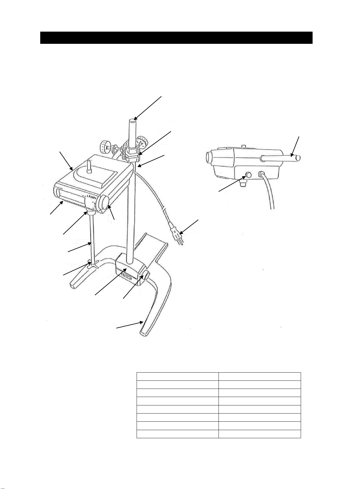
2. Assemble according to the external view.
2.1. (Optional accessory, frame)
Put the support ①in the support fixing boss ④, then fix it firmly with the tightening
knob③.
2.2. Attach the clamp ⑧to the frame support ①, then fix the main body ⑥
.
2.3. Screw the stirring propeller ⑩into the stirring shaft ⑨, and insert the stirring shaft ⑨into the
chuck ⑪, then fix it so as fastening at three chuck holes to be equal by the chuck handle.
Danger
Choose a receptacle with grounding connectors not to get electric shock. If there are only
bipolar receptacle available in your workshop, connect an optional grounding adapter to the
oven’s power plug, and connect the adapter’s grounding wire to a receptacle’s grounding
terminal.
Don’t connect the grounding wire to gas or water piping.
Don’t use branching plug socket, which causes heat generation of the power line.
Don’t install the LABO-STIRRER in the place where inflammable gas or corrosive gas is
generated.

7
OPERATION
1. Connect the power supply cord to the power supply ofAC 115V.
2. Length of the stirring shaft shall be adjusted according to the vessel in which stirring liquid is
contained. However, you use it with the shaft being put out as short as possible. Because there
will be fewer run-out of shaft and life of the bearing will be lengthened.
3. Turning the speed control knob ⑬clockwise, power supply switch will be on and the further you
turn it clockwise, the faster its revolving speed will be Confirm the revolving speed by the display
panel when you set it.
4. The torque monitor is not lit up when load is small. However it is lit up from the left side (green)
as load is increased. When it becomes over the load the red lamp (right end) blinks and
revolving speed is decreased. If the load is further increased, the red lamp is lit up and the
operation is stopped.
Caution
If the speed control knob is turned clockwise rapidly, set revolving speed may be exceeded,
however it is not trouble since it may become to the set value soon.
Do not operate continuously in the overload condition. Thermal switch of the motor is activated
and the operation is stopped. In this case, leave it for some and start the operation again after
cooling.
Danger
This unit has the structure which is hard to catch fire, however, it does not have an
explosion-proof condition, you cannot use it especially at place where there is a danger of
inflammability.

8
MAINTENANCE
Daily Inspection and Maintenance
Danger
Before starting inspection or maintenance, disconnect the power plug from the receptacle or
turn OFF the breaker on the distribution board.
Don’t disassemble the unit.
When you remove dirt or stain from the unit’s resin parts and the control panel, use soft wet
cloths. Don’t use benzene, thinner, cleanser and hard brush, which will cause deformation,
qualitative deterioration or discoloring of those components.

9
AFTER SALE SERVICE AND WARRANTY
When you call us for repair
If a trouble happens on the LABO=STIRRER, stop the operation immediately, turn off the power
switch, and disconnect the power plug from the receptacle. Thereafter, contact our sales
representative in your vicinity or our service office.
Check the warranty card or the name plate of your LABO-STIRRER and give information below.
Model of your unit;
Serial product number of your unit;
Date of your purchase; and
Trouble of your unit (as detail as a possible)
Warranty Card (attached to your LABO-STIRRER)
Together with the LABO-STIRRER, our sales representative or service office issues a warranty
card. Check the name of the shop from which you purchased to the unit, and the date of your
purchase. Keep the warranty card in a safe place after reading its contents carefully.
Warranty period is 1 (one) year after the date of your purchase. During this warranty period, we
will offer free repair service on the basis of the conditions provided on the warranty card.
If you need repair service after expiration of the warranty period, contact our sales
representative in your vicinity or service office for advice. We will offer charged repair service
when such service can maintain the performance of your unit.
Minimum Inventory Period of Repair Parts
Repair parts will be available for at least 7 years after termination of our production of
LABO-STIRRER. Repair parts means the parts which are necessary to maintain the performance of
the unit.

10
TROUBLESHOOTING
Trouble
Counteraction
The shaft does not revolve
although the power switch is
turned ON. The display panel
is not lit up.
Check if the power cable is connected to a receptacle or a
distribution board.
Check if it is power failure.
Check if the fuse is proper.
The display panel is lit up,
however, the shaft does not
revolve.
Check if it operated in the overload condition. In this case,
leave it for some time start it again.
Vibration is severe.
Check if the stirring shaft is set correctly.
Revolving speed does not
increase. The shaft stops
soon.
Check if the viscosity of the solution is proper.

11
SPECIFICATIONS
[LR500 Series]
Model
LR500A
LR500B
Revolving Speed Range
34 ~340 rpm
100 ~1,000 rpm
Max. Torque
1.94 N・m
(20 kg-cm)/
340 rpm
0.98 N・m
(10 kg-cm)/
1,000 rpm
Revolving Display
Digital 3 columns
Digital 3 columns(×10)
Torque Display
LED two step display + Overload display
Motor
DC brushless motor
70W
100W
Revolving Control
Speed feed back control
Working Shaft
~φ10 mm
Safety Mechanism
Overload stopping
Revolving Mechanism
Direct drive system
External Dimensions
164 (W) × 252 (D) × 174 (H) (excluding arm)
Weight
4.2 kg
4.0 kg
Rated Power
AC115V 2.1A
AC115V 2.6A

12
WIRING DIAGRAM
Symbol
Part Name
Remarks
K1
Control board
K2
Display board
P
Power plug
F
Fuse
VR
Volume
Volume with
switch
S
Switch
M
Motor
J1
Jumper
J2
Jumper
FM
Cooling fan
LR500A
X
Relay
Jumper Connecting Method by Model
Model
Jumper
J1
J2
LR500A
○
○
LR500B
○
×
○ : CLOSE
× : OPEN
AC115V

13
REPLACING PART TABLE
Symbol
Part Name
Code No.
Specifications
Manufacturer
K1
Control
Board
LR500A
LR5000102
Yamato Scientific
LR500B
LR5000104
Yamato Scientific
K2
Display Board
LR4000112
Yamato Scientific
P
Power Plug
LR4000113
T1-3a
Yamato Scientific
VR
Volume with Switch
LR4000117
RV24YN20F-MF
Teikoku Communication
Industry
M
Motor
LR500A
LR5000101
Yamato Scientific
LR500B
LR5000103
Yamato Scientific
F
Fuse
LR4000116
φ5.2 × 20 mm 3 A
FM
Cooling Fan
LR4000123
109 - 180

14
OPTIONAL ACCESSORIES
Part Name
Dimensions and Type
Goods Code
No.
Y-shaped frame
Support:
Foot:
Weight:
725 (L) ×25 (O.D.) mm
400 (W) × 420 (D) mm
Approx. 7 kg
231086
Stirring
Propeller
Four blades
(Blade diameter) 75, 60, 40 mm
000141
Two blades
(Blade diameter) 100, 28 mm
000141
Blade for narrow
port
(Revolving diameter) 45 mm
000141
Glass blade
(Blade diameter) 60 mm
000141
Turbine with disc
(Blade diameter) 100, 60 mm
000141
Turbine with disc
for two steps
(Blade diameter) 60 mm
000141
Stirring shaft
800 (L) × 10 (O.D.) mm
000141
Water tank mounting fitting
231032
Auxiliary stirrer
231096
Low pressure stirrer
Grinding type
$24/40
231097
Grinding type
$29/40
231098
Grounding adaptor
000141

15
REFERENCE DATA
*Standard accessory is used for the stirring propeller.
LR500 Series: O.D. 75 mm (four blades)
*Following beakers are used.
10 liter beaker for 8 liter stirring volume.
5 liter beaker for 4 liter stirring volume.
3 liter beaker for 2 liter stirring volume.
1 liter beaker for 0.5 liter stirring volume.
*Unit of viscosity: 1Pa・s =
3
10
cP
*Judge the stirring condition by visual inspection.

Limited Liability
Always operate equipment in strict compliance to the handling and operation
procedures set forth by this instruction manual.
Yamato Scientific Co., Ltd. assumes no responsibility for malfunction, damage,
injury or death, resulting from negligent equipment use.
Never attempt to disassemble, repair or perform any procedure on LT500 series units
which are not expressly mandated by this manual. Doing so may result in equipment
malfunction, serious personal injury or death.
Notice
●Instruction manual descriptions and specifications are subject to change without
notice.
● Yamato Scientific Co., Ltd. will replace flawed instruction manuals (pages missing,
pages out of order, etc.) upon request.
Instruction Manual
Stirrer
LR500A/500B
First Edition June 8, 2017
Yamato Scientific America Inc.
925 Walsh Avenue, Santa Clara, CA 95050
Phone: 800.292.6286 / 408.235.7725
http://www.yamato-usa.com
This manual suits for next models
3
Table of contents
Other Yamato Mixer manuals