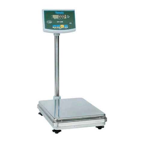
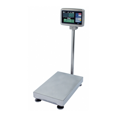
Yamato DP-6700 User manual

YCO-201008
DP-6700 Technical Manual
Digital Platform Scale
(US Version)
YAMATO SCALE CO., LTD.
YAMATO CORPORATION
1775 S. Murray Blvd.
Colorado Springs, CO 80916 USA
Tel (719) 591-1500 Fax (719) 591-1045
YAMATO TECH CORPORATION
#112-19425 Langley By-Pass
Surrey, B.C. V3S 6K1 Canada
Tel (604) 533-2338 Fax (604) 533-0827
www.YamatoCorp.com

YCO-201008
DP-6700 Technical Manual

YCO-201008
DP-6700 Technical Manual
Table of Contents
* This manual is divded into several chapters that discuss specc topics
Chapter 1 Adjustment method 1-1
1.1 Basic specications (dimensions and capacity) 1-1
1.2 Appearance and names of sections 1-2
1.2.1 External dimensions and names of sections 1-2
1.2.2 Package dimensions and packing methods 1-3
1.2.3 Display unit and key operation 1-4
1.3 How to use test mode and adjustment method 1-5
1.3.1 How to switch to test mode and meanings of panel indications 1-5
1.3.2 How to display internal count 1-5
1.3.3 How to set parameters and their meaning 1-7
1.3.4 List of initial parameters values before shipment by scale
type and weighing capacity 1-14
1.3.5 Initializtion of CPU board 1-22
1.3.6 Span adjustment (calibration) 1-24
1.4 Wiring diagram 1-25
1.5 Error Code 1-26
Chapter 2 Communication option 2-1
2.1 How to make the settings for optional communication 2-1
2.1.1 Parameter values when using communication options 2-1
2.1.2 Overview of ZBee communication options 2-2
Chapter 3 How to disassemble 3-1
3.1 Precautions before carrying out repairs 3-5
3.2 How to remove the board 3-5
3.2.1 Tips for assembly of the indicator 3-9
3.3 How to replace the load cell 3-10
3.3.1 How to replace the load cell 3-10
3.3.2 Tips for installation of the load cell 3-14
3.4 How to perform eccentric error adjustment 3-15
Chapter 4 Procedures for maintenance, inspection and other responses 4-1

YCO-201008
DP-6700 Technical Manual
1.1 Basic specications (dimensions and capacity)
(1) The DP-6700 series supports two types of power sources - 6VDC (D-Series batteries) and optional
AC adaptor.
(2) The dedicated AC adaptor must be used.
NOTE: To prevent leakage of battery uid, never use the AC adaptor in combinatin with the batteries
Chapter 1 Adjustment method
1-1

YCO-201008
DP-6700 Technical Manual
1.2 Appearance and name section
1.2.1 Appearance and names of sections
1-2
Chapter 1 Adjustment method

YCO-201008
DP-6700 Technical Manual
1.2.2 Package dimensions and packing methods
The following package demensions, weight and packing methods are those for standard products
300
400
890
17kg
1-3
Chapter 1 Adjustment method
Fixing material for
display unit
Plastic bag
Display unit
Fixing material for
display unit A
Operation manual
Main body cover
Weighing section
Bottom pad for main body
Spacer
Bottom pad for main body
Front fixing
material
Front fixing
material
Front fixing
material

YCO-201008
DP-6700 Technical Manual
1-4
1.2.3 Display unit and key operation
Chapter 1 Adjustment method

YCO-201008
DP-6700 Technical Manual
1-5
Chapter 1 Adjustment method
1.3 How to enter test mode and adjustment method
1.3.1 How to enter test mode and meanings of panel indications
NOTE: In case of veried model, it is necessary to break the seal before accessing a deep-set switch.
Once breaking the seal, the verication become invalid
1.3.2 How to display internal count - Figure. 1-1 Display in Test mode

YCO-201008
DP-6700 Technical Manual
1-6
In test mode, the following types of the internal count are displayed. When the key is pressed, the interal count, power
supply voltage, display cheeck and others are cyclically shown on the panel in the following order.
Chapter 1 Adjustment method

YCO-201008
DP-6700 Technical Manual
1.3.3 How to set parameters and their meanings
The parameters are divided into 3 groups, "User Parameter," "System Parameter" and "Factory
Parameter."
In test mode, you can switch to any of the parameter modes.
In normal mode where a weight is displayed, only the user parameters can be changed. You must
turn off the power to exit parameter mode.
(1) User Parameter Mode (to congure communication functions, multifunction, and others)
Related page: Page 1-10
(2) System Parameter Mode (to set stability detection and others)
The user parameters and intended for users to change the functions of the scale according to the
user specications. The following parameters from 01 to 29 and d0 to F0 can be set, conrmed and
changed
When replacing the CPU board, make sure to check if the parameter settings are correct referring
to the parameter list.
1-7
Chapter 1 Adjustment method

YCO-201008
DP-6700 Technical Manual
1-8
Chapter 1 Adjustment method
User Parameter
No. Item Value Function
1 Function Select 000:
001:
002:
003:
004:
Suspend Functions (Default)
Fixed Weighing (Packing)
Check Weighing
Grading
Counting
2 Number of Grading Ranks 000:
000-015:
Suspend Functions
006 (Default)
3 Buzzer
*Valid at packing & Check Weighing
000:
001:
002:
003:
004:
No Sound (Default)
Beep at Under Weight
Beep at Acceptable Weight
Beep at Over Weight
Beep at Under & Over Weight
4 Judgment for Grading (LED)
Judgment for Checking weighing
(Buzzer) #03 ≠ 0
000:
001:
Judgment even at instability
Judgment even at Stability Only
5Auto-Off Timer
*Only for Battery Operation
000:
001:
002:
003:
004:
005:
No Auto-Off
5 Minutes After No Use
10 Minutes After No Use
15 Minutes After No Use
30 Minutes After No Use
60 Minutes After No Use
7 Flicker of Weight Display 000:
001:
002:
003:
004:
005:
No Flicker (Default)
Flicker at Under Weight
Flicker at Acceptable Weight
Flicker at Over Weight
Flicker at Under & Over Weight
Flickers according to the Parameters #03. Settings
8 Grading Method 000:
001:
002:
003:
Additive (Normal) Grading
Subtractive Grading (Default)
Additive Matrix Combination (Option)
Subtractive Matrix Combination (Option)
9 Gravity Compensation
(Depnding on #47)
000:
001-029:
030-210:
No Compensation
Prohibit to Set
(Acceleration of Gravity (m/s2) - 9.7600) X 10000/5 +30 (offset)
10 Scale ID (For option) 000-099: 000 (Default)
10 Communication Mode 000:
001:
002:
003:
004:
005:
No Communication
Automatic Sending / Addition at Being Stable
Automatic Sending/ Addition after Removal
Manual Sending/ Addition by "ADD" key (Default)
Continuous Sending For Optional Function
Automatic Sending/ Addition at Acceptable Weight
11 Communication Method 000:
001:
002:
003:
004:
005:
006:
Bluetooth Wireless Communication
ZBee Wireless Communication
RS232C Output
USB Memory
Bluetooth Wireless Printer
Addition (No Communication) (Default)
Auible Grading
13 Communication Data 000:
001:
002:
Net Weight Once (Default)
Net. Tare and Gross Weight Once
Net and Tare Weight Once

YCO-201008
DP-6700 Technical Manual
Chapter 1 Adjustment method
1-9
User Parameter
15 Communication Speed
*Valid at #13 = 002
000:
001:
002:
003:
004:
005:
9600 bps (Default)
2400 bps
4800 bps
9600 bps
19200 bps
38400 bps
16 Character Length
*Valid at # 13 = 002
000:
001:
8 Bits (Default)
7 Bits
17 Parity
*Valid at # 13 = 002
000:
001:
002:
No Parity (Default)
Odd Parity
Even Parity
18 Stop Bit
*Valid at # 13 = 002
000:
001:
1 Bit
2 Bit
19 Print 000:
001:
No Designation (Default)
Only Total Weight is printed
23 Send Display During Transfer 000:
001-008:
No Function
Displaying "Send" for the designated time
001 (Default)
24 Unit at Power On
*Valid at #41 = 002
000:
001:
002:
003:
kg(g)
lb
oz
lb:oz
25 Brightness of LED Lamp 000:
001:
002:
Low/Dull (Default)
Middle
High/ Keen
26 Date & Time for Communication 000:
001:
No Date and Time are Sent
Date and Time are Sent
27 Setting Value Print for Multi-Function 000:
001:
No setting Value is Printed
Setting Value is Printed
28 Paper Feed 000:
001-015:
No Paper Feed (Default)
The Designated Lines are Fed Automatically
29 Printing Character 000:
001:
Chinese Character
Alphabet
C3
(123)
Zero Addition 000:
001:
No Adding with the indication being 0
Adding even if the indication is 0
do-
#F1
Setting for Audible Grading 000-014: Do Not Change

YCO-201008
DP-6700 Technical Manual
How to Set User Parameters
Prodcedure Indication
How to switch to User Parameter Mode:
There are the following two ways to switch to user parameter mode:
In normal mode, press the key
while holding down the key; and switches to user param-
eter mode.
The user parameters can also be set in dealer parameter
mode that will be described later
See (2) System Parameter Mode (to set stability detection and oth-
ers) on Page 1-10 for how to set the dealer parameters.
Going to the next parameter:
Press key to go to the next parameter.
To change the setup vaue, enter a new value and go to the next
parameter.
Make sure to go to the next parameter to enable the new value.
If you exit before moving to the next parameter, the system dis-
cards the entered value.
Going back to the previous parameter:
To go back to the previous parameter, press the key while
holding down the key.
+1 operation for parameter value:
Press the key to increment the parameter value by 1.
If the value exceeds the setting range, the value returns to 0
-1 operation for parameter value:
Press the key to decrement the parameter value by 1 (or
increment it by -1)
If the current setup is 0, the maximum value appears.
1-10
Chapter 1 Adjustment method

YCO-201008
DP-6700 Technical Manual
+10 operation for parameter value:
Press the key while holding down the key to
increment the parameter value by 10.
If the setting range of the parameter is less than 10, "0000"
stays on the panel in spite of the operation.
-10 operation for parameter value:
Press the key while holding down the key to dec-
rement the parameter value by 10 (or increment it by -10).
If the settings range of the parameter is less than 10, the
maximum setup limit for the parameter stays on the panel
in spite of the operation.
(2) System Parameter Mode (to set stability detection and others)
Related page: Page 1-15 1.3.1 How to enter test mode and meanings of panel indications
System parameter mode is used to change dealer parameters such as stability detection. The following
parameters from 30 to 39 and B1 to C3 can be set, conrmed and changed.
In this mode, (1) user parameters fromt 01 to 29 can be set, conrmed and changed.
To switch to dealer parameter mode, you must switch to test mode rst. See 1.3.1 How to enter test
mode and meanings of panel indications on Page 1-5 for switching to test mode.
When you replace the CPU board, make sure to check if the parameters settings are correct, referring
to the parameter list.
System Parameters
No. Item Value Function
30 System ID 016: Prohibit to Change
31 Stable - State Sampling Count 000-015: *Use the time of "setting value X 2"
32 Stable - State Count 000-050:
33 Very Stable - State Count 000-050:
34 Stable - State Releasing Count 000-050:
35 Stable - State Average Count 000-015:
37 Data Accumluation at Multi-
Function
000:
001:
No Data Accumulation
Data Accumulation
38 Local Multi-Function setting dur-
ing communication
000:
001:
Editable
No Editable
39 Skip in Reading on Display 000:
001-015:
Skip in Reading Disable
Skip in Reading at specied
1-11
Chapter 1 Adjustment method

YCO-201008
DP-6700 Technical Manual
No. Item Value Function
B1(111) Moving Average Filter 1 000-0008: Moving Average Tap NO. (Invalid Less Than 2)
B2(112) Moving Average Filter 2 000-0008: Moving Average Tap NO. (invalid Less Than 2)
B3(113) Moving Average Filter 3 000-0016: Moving Average Tap NO. (invalid Less Than 2)
B4(114) Moving Average Filter 4 000-0016: Moving Average Tap NO. (invalid Less Than 2)
C0(120) Load / Unload Judge 004-255:
C1(121) Buzzer at Data Transmission 000:
001:
No Sound
Sound
C2(122) One-Time Addition 000:
001:
Addition any numbers of times
One-Time Addition
How to Set System Parameters
Description Indication
Display the internal count in test mode, referring to 1.3.1 How
to enter test mode and meanings of panel indications on
Page 1-5.
When the internal count is shown on the panel, press the
key while holding down the key; and it switches to dealer
mode.
Going to the next parameter:
Press key to go to the next parameter.
To change the setup value, enter a new value and go to the
next parameter.
Make sure to go to the next parameter to enable the new value
If you exit before moving to the next parameter, the system
discards the entered value.
Going back to the previous parameter:
To go back to the previous parameter, press the key while
holding down the key.
+1 operation for parameter value:
Press the key to increment the parameter value by 1.
Keeping the key down for a while automatically increments
the parameter value by 1 continuously
If the value exceeds the setting range, the value returns to 0.
1-12
Chapter 1 Adjustment method

YCO-201008
DP-6700 Technical Manual
- operation for parameter value:
Press the key to decrement the parameter value by
1 ( or increment it by -1)
Keeping the key down for a while automatically
decrements the parameter value by 1 continuously.
If the current setup value is 0, the maximum value ap-
pers.
+10 operation for parameter value:
Press the key while holding down the key to
increment the parameter value by 10.
If the settings range of the parameter is less than 10.
"000" stays on the panel in spite of the operation.
-10 operation for parameter value:
Press the key while holding down the key to
decrement the parameter value by 10 (or increment it by
-10).
If the setting range of the parameter is less than 10,
the maximum setup limit for the parameter stays on the
panel in spite of the operation.
Returning to test mode:
Press the key while holding down the key, and
it returns to test mode.
Note: Turn off the power and restart to make changes
effective.
(3) Factory Parameter Mode (to set increment, area, default values and others)
Related pages: Page 1-5 1.3.1 How to enter test mode and meanings of panel indications
Page 1-22 1.3.6 Span adjustment (calibraton)
System parameter mode is used to change the parameters that determine the specications of the scale.
The following parameters from 40 to B8 can be set, conrmed and changed. To switch to system
parameter mode, you must switch to test mode rst. See 1.3.1 How to enter test mode and
meanings of panel indications on Page 1-5 for switching to test mode. When you replace the CPU
board make sure to check the correctness of the parameters, referring to the parameters table.
1-13
Chapter 1 Adjustment method

YCO-201008
DP-6700 Technical Manual
Factory Parameter
No. Item Value Function
40 Gravity Compensation 000:
001-029:
030-210:
No Compensation
Compensation for a specied area (Japan Only)
(Acceleration of Gravity (m/s2) - 9.7600) x 10000/5 + 30 (offset)
41 Scale Mode 000:
001:
002:
003-007:
Fixed single increment
Multi-Increments
YCO Mode
Prohibit to set
42 Multi-Increments,
Complex Increment Mode
000:
001:
002:
003:
004:
005:
006:
Fixed single increment
Fixed accuracy, 3 Capacities
Fixed accuarcy, 2 Capacities
Increment change at 50% FS, 2 Capacities
Increment change at 80% FS, 2 Capacities
Increment change at 64% FS, 2 Capacities
Increment change at 40% FS, 2 Capacities
43 Weighning Capacity
Mantissa
000-099:
44 Weighing Capacity Index 001-004:
45 Increment of Small Capacity 000:
001:
002:
003:
004:
005:
006:
007:
1
2
5
10
20
50
100
200
46 Location of Decimal Point 000:
001:
002:
003:
004:
0
0.0
0.00
0.000
0.0000
47 Testing for Certication 000:
001:
Veried
Not Veried
50 Calibration with lb weight 000:
51 lb: Weighing Capacity
Mantissa
000-099:
52 lb: Weighing Capacity Index 001-004:
53 lb: Location of Decimal Point 000:
001:
003:
0
0.0
0.00
0.000
54 lb: Increment 000:
001:
002:
003:
004:
005:
006:
007:
1
2
5
10
20
50
100
200
1-14
Chapter 1 Adjustment method

YCO-201008
DP-6700 Technical Manual
Chapter 1 Adjustment method
1-15
55 oz: Weighing Capacity
Mantissa
000-099: Specied by Pound (oz = lb* 16)
56 oz: Weighing Capacity Index 001-004:
57 oz: Location of Decimal Point 000:
001:
002:
003:
0
0.0
0.00
0.000
58 oz: Increment 000:
001:
002:
003:
004:
005:
006:
007:
1
2
5
10
20
50
100
200
60 Comma Display 000:
001:
Decimal Point
Comma
61 Weighing Unit (g Mode) 000:
001:
002:
None
g
kg
62 Weighing Unit Display 000:
001:
No unit display
Unit display
65 Internal Resolution 000:
001-255
Prohibit to set (scale function invalid)
Normal Setting = 010
66 ADC Self Calibration
ADS1225IRGVT
025:
Except 025
Valid
Invalid (Prohibit to set)
67 ADC Cutoff Bit No. 000-003:
004-007
Set at 6 Automatically
68 Over scale 000-100
70 Zero point range (% for full
capacity)
000-100 Set zero point range in % for full scale
71 Zero point range / plus side (%) 000-100 Value on plus side within the setting range on #70
72 Tare clear by reset key 000:
001:
Not clear tare value by pressing zero reset key
Clear tare value by pressing zero reset key
73 Zero tracking timing 000:
001-015:
No zero tracking
Zero tracking at the specied interval (Count)
74 Tare Function 000:
001:
002:
No tare function
One-time tare
Consecutive tare
75 Zero reset under tare operation 000:
001:
Valid
Invalid
76 Simple combination function 000:
001:
Invalid
Valid
77 Simple test mode 000:
001:
002:
003:
004:
005:
Entered by key operation only (Test pin is invalid)
Entered by key operation only, user parameter is invalid
Entered by key operation & test pin
Entered by key ope. & test pin, user parameter is invalid
Entered by test pin only (Key ope. is invalid)
Entered by test pin only, user parameter is invalid

YCO-201008
DP-6700 Technical Manual
Chapter 1 Adjustment method
1-16
79 Raise precision of increment 000:
001:
Invalid
Valid
80 Data Transmission at simple
combination function
000:
001:
Not send
Send displayed value
81 Fixed weighing function 000:
001:
Invalid
Valid
82 Checkweighing function 000:
001:
Invalid
Valid
83 Grading function 000:
001:
Invalid
Valid
84 Counting function 000:
001:
Invalid
Valid
85 Display hold function 000:
001:
No display hold function
Display hold function (Range depends on #C 0)
86 Time of display hold 000:
001-015:
Release display hold around "0"
Display hold around "0" for specied time
87 Adding weight operation under
display hold function
000:
001-005:
Invalid
Update the wieght indication when more than the specied
divisions are changed
88 Time delay for span adjustment 000:
001-015:
No time delay
Get a span value after the specied time (sec)
90 Mechanical Zero 1 000-255: Automatically set at span adjustment (Prohibit to change)
91 Mechanical Zero 2 000-255: Automatically set at span adjustment (Prohibit to change)
92 Mechanical Zero 3 000-255: Automatically set at span adjustment (Prohibit to change)
93 Span coefcent 1 (small) 000-255: Automatically set at span adjustment (Prohibit to change)
94 Span coefcent 2 (small) 000-255: Automatically set at span adjustment (Prohibit to change)
95 Span coefcent 3 (small) 000-255: Automatically set at span adjustment (Prohibit to change)
96 Span coefcient 1 (middle) 000-255: Automatically set at span adjustment (Prohibit to change)
97 Span coefcient 2 (middle) 000-255: Automatically set at span adjustment (Prohibit to change)
98 Span coefcient 3 (middle) 000-255: Automatically set at span adjustment (Prohibit to change)
99 Span adjustment zone 000-210: Automatically set at span adjustment (Prohibit to change)
A0(100) Board sensitivity adjustment 1 000-255: Automatically set at board sensitivity adjustment (Prohibit to
change)
A1(101) Board sensitivity adjustment 2 000-255: Automatically set at board sensitivity adjustment (Prohibit to
change)
A2(102) Board sensitivity adjustment 3 000-255: Automatically set at board sensitivity adjustment (Prohibit to
change)
A3(103) Span coefcient 1 (Large) 000-255: Automatically set at span adjustment (Prohibit to change)
A4(104) Span coefcient 2 (Large) 000-255: Automatically set at span adjustment (Prohibit to change)
A5(105) Span coefcient 3 (Large) 000-255: Automatically set at span adjustment (Prohibit to change)
A6(106) Span adjustment zone 000-255: Automatically set at span adjustment (Prohibit to change)
A7(107) "lb:oz" Display 000:
001:
Valid "lb:oz" display
Invalid "lb:oz" display
A8(108) LED external output 000:
001:
Invalid
Valid
A9(109) Transmission for TDW 000:
001:
Continuous transmission at #11 = 004
Transmission every stable at #11 = 004 (For TDW)

YCO-201008
DP-6700 Technical Manual
1-17
Chapter 1 Adjustment method
B0(110) Factory setting 000:
001:
002:
003:
004:
005:
006:
007:
Not use default setting
DP-6700 30kg/10g, 1/3000, Veried Model
DP-6700 60kg/20g, 1/3000, Veried Model
DP-6700 150kg/50g 1/3000, Veried Model
DP-6700 150g/100g, 1/1500, Veried Model
DP-6700 30kg/10g, 1/3000, Non-Veried Model
DP-6700 60kg/20g, 1/3000, Non-Veried Model
DP-6700 150kg/50g, 1/3000, Non-Veried Model
B5(115) Transmission of ad value 000:
001:
002:
003:
004:
Not send
Raw (2 batches average) + 4th ltering
Raw (2 batches average) + Final ltering
4th ltering + Final ltering
4th ltering + Final ltering at very stable - 20
B6(116) Input judgment of lter "L" at
stable
000-255 By 0.01% for capacity
B7(117) Input convergence of lter "S"
at stable
000-015: By 0.01% for capacity
B8(118) Input difference of lter "S" at
stable
000-015: By 0.01% for capacity
B9(119) Auto tare delay, subtracting
grading
000-099: Delay time (x10ms)
C7(127) Keyboard tare 000:
001:
Keyboard tare is invalid
Keyboard tare is valid
C8(128) Recommended calibration
method
002:
003:
004:
005:
006:
007:
Using 2 points - zero point and full capacity
Using 3 points - zero, 1/2 cap, and full capacity
Using 4 points - zero, 1/2 cap, full cap and 1/2 cap on return
Using 4 points - zero, 500 increments, 1/2 cap and full cap
Using 4 points - zero, 500 increments, 2/3 cap and full cap
Using 4 points - zero, 1/3 cap, 2/3 cap and full cap
C9(129) Store display hold mode 000-001: Memorize display mode and revert to current status at power
on next time
How to Set Factory Parameters
Description Indication
Display the internal count in test mode referring to 1.3.1 How
to enter test mode and meanings of panel indications on
Page 1-5. When the internal count is shown on the panel,
press the key while holding down the key; and it
switches to span adjustment mode. (See 1.3.6 Span adjust-
ment (calibration) on Page 1-22)
In span adjustment mode, press key while holding down
the key; and it switches to system parameter mode.
Going to the next parameter:
Press the key to go to the next parameter.
To change the setup value, enter a new value and go to the
next parameter. Make sure to go to the next parameter to
enable the new value. If you exit before moving to the next
parameter the system discards the enter valve
Other manuals for DP-6700
1
Table of contents
Other Yamato Scale manuals

Yamato
Yamato PPC-200 User manual

Yamato
Yamato UDS-1V-WP User manual

Yamato
Yamato PLS Series User manual

Yamato
Yamato DP-6900 User manual

Yamato
Yamato DSR-400 User manual

Yamato
Yamato PPC-300 User manual

Yamato
Yamato AW-300P User manual
Yamato
Yamato AW-WPS User manual

Yamato
Yamato DP-6100GP User manual

Yamato
Yamato AW-WLG Series User manual

Yamato
Yamato DKS-3002 User manual

Yamato
Yamato DP-5602 User manual

Yamato
Yamato DSR-200 User manual

Yamato
Yamato Delicell User manual

Yamato
Yamato PPC-101 User manual
Yamato
Yamato DP-6900 User manual

Yamato
Yamato DP-6200 User manual

Yamato
Yamato BC-10 User manual

Yamato
Yamato Just NAVI J-101W User manual

Yamato
Yamato DKS-3002 User manual