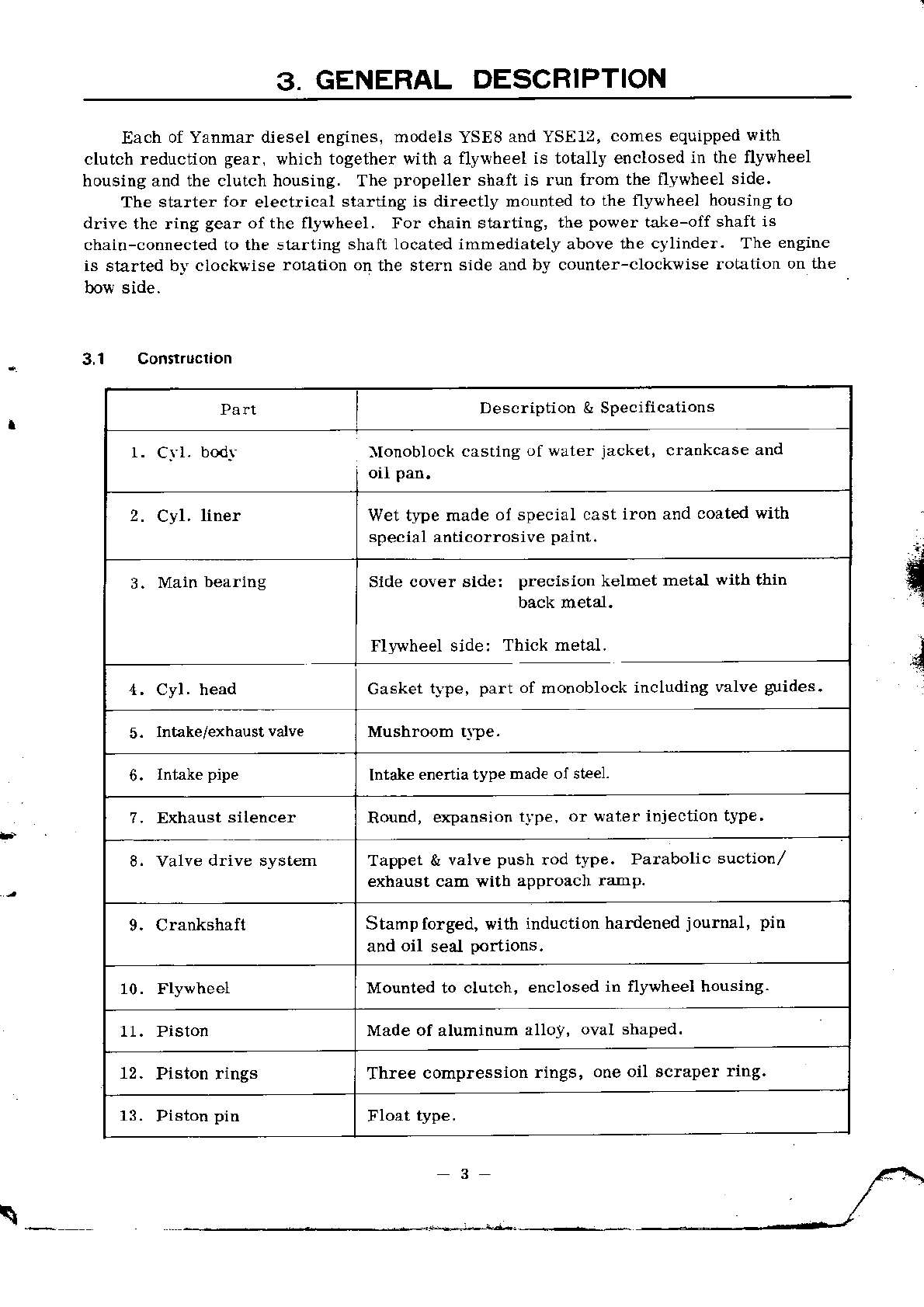
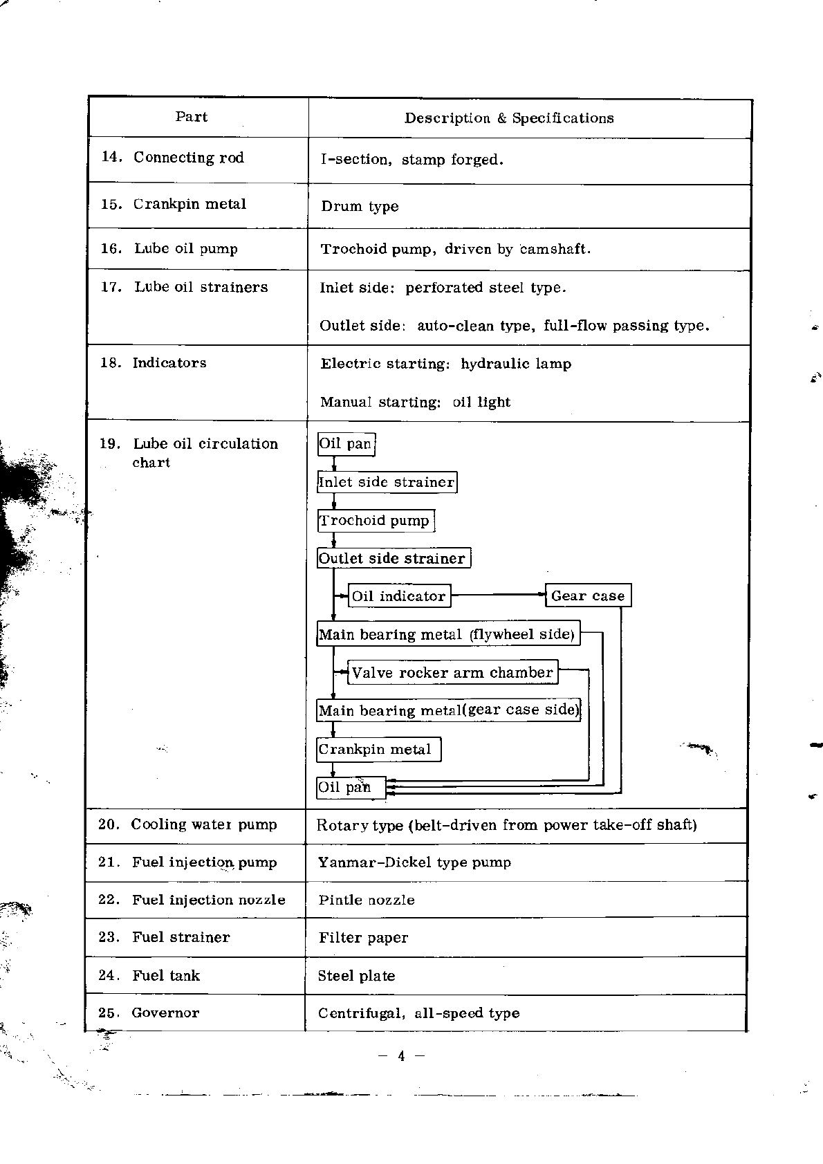
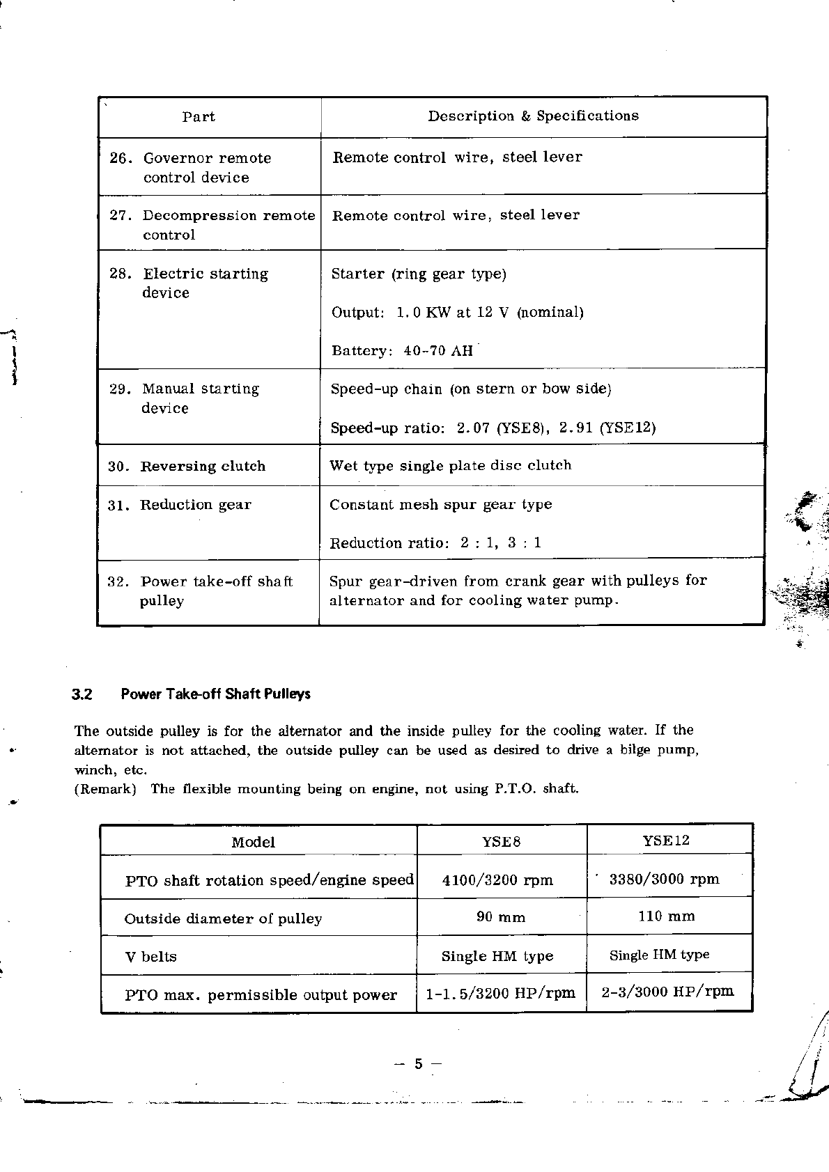
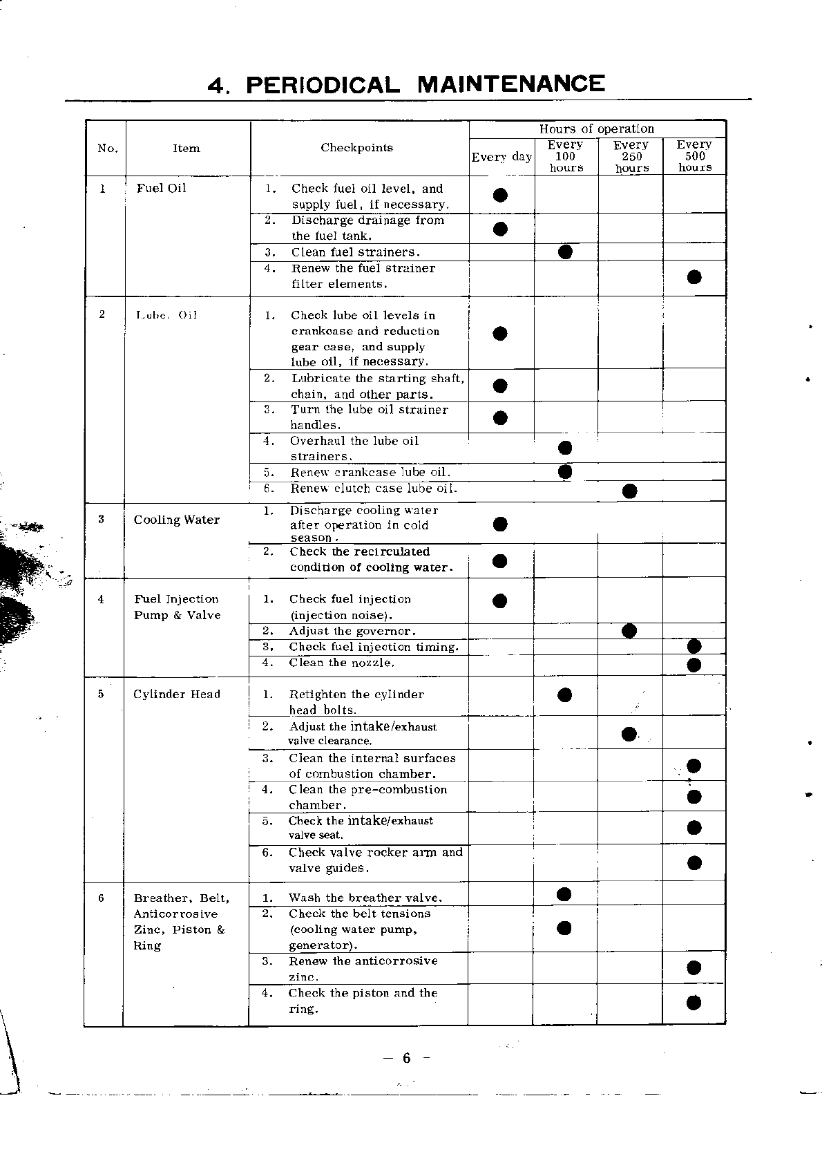
Yanmar YSE8 User manual

,€:t
iIODEL
YSI

]\
1
2.
3.
4.
5.
j
7.
8.
ENGINE I\ PHOTOCRAPHS
OUTST.{\DNG FE.{TLRES
GENER{L DESCRIPTTON
3.2 Po*er Take-off ShaftPulleys .. ..
PERIODICAL }LdII{TENANC E
FUEL ,\\D LUBRICATING OILS
5.
t FuelOils
;. 1.1 Propert! requirements
byviscosity 7
-8
I
o'/-.u,(F",.^*.(r*/AJ,".,
.
CONTENTS cr/ol -4"!cl,( .
Page
OF YSE SERIES
Dlanos
1
2
3
3
5
6
7
7
7
5.2.2 Classification
5.2.3 Recommended
6. TROUBLESHOOTING .....,..,....,.,. 10
-
6.1 EngineDoes
\o1Start . .,.,.,........,...... 10
6.2 Difficult
Srafi-up ...,. ...,..,,
....
.,
.
., 1l
6.3 Bad
ExhaustColor ....,...I2
. '=--,---6.4 Momentarl
High-speed
Relolution ... ... ,....,.. 12 '.
6,5 Hunting ...,..........
12
6.6 OutputDecrease
. ............. 13
6.? Knocking during Operation 13 ,
6.8 SuddenEngineStop ..,........... . 14 l
6.9 Lubricating
OilLeak ...... ......,....... 14 I
6.10
Fu€l
Oil
leak
... ...
-............... 14
6.11Water
Leak ...... ..... . 15
6,12 CoolingWaterFailure .. .......,. 15
6.13ClutchSlip
............. ................
15
WEARLIMIT OF EACH
MAIN PAR'T ... ..,........... TE
INSPECTIONAND sERVrcrNdoF MAIN p-{RTS .. ..-.-.-rih.-.. ........ t7
8;l Fuel InjectionPumpancl
Nozzle ....,. ,:,..,.. .,,,.. .. . 17
8.1.1 Fuelinjection
pump ......... 77
8.1.2 Fuelinjectionnozzle(throttleno2z1e1.,.,.,..,..................19
8.1.3 Air venting ...
..
..
.
.
..
,
.....
.
.
.
.
. 21
8.2 Cooling
Water
Pump .....,..22
8.3 CylinderHead .-..-.-...-.........-..24
,ta
_f

Page
cting
Rod
Assembly .,............... 26
30
32
8.4
8.5
8.6
8.7
Piston and Conne
Cylinder Liner
Crankshaft andMain
ElectdcaI EquipmentBeafing Metal
8.7.
1 Stater
8.7.2 Generator 36
37
38
38
38
39
40
4I
9. ADIUSTMENTS
9.1 Governor
Lever
9.1.1 Adjustment
procedure
9.1.2 Readjustment
procedure t
9.2 Inbke/ExhaustValve 39
39
39
4T
'4r
9.2.1 Adjustment
procedure
._9.3 Fuel Injection Timing
9.3..1.. Checkinghints
" :'.' ","'-"_b "'_"_
9.3.2 Adjustment
procedure
DISASSEMBLY
10,1 Preparation
10.2 Serviceman'sKit
10.2.1 General
tools
10.2.2 Specialtools
10.2.3 Measuring
instruments
10.2.4 Others
10.3 Precautions
10.4 Cl
ul.ch
Disussemblj Prucedu-re
42
42
43
43
43
4?
48
11,
12. STERN ARN,ANGEMENT
REASSEMBLY
11.1 Precautions
I
I
[,
t. "-llkl =-4--

1. ENGINE IN PHOTOGRARHS
Eyenur {for
hosi ngenqine)
F
t
t
(only for electi..l startng)
Propeller
shaft
;uprinq

2.OUTSTANDING
FEATURES
OF YSESERIES
1. Its extra-compactness, light weight, andlarge outputpermit engineroom to be
miniaturized.
2. Wet tlpe single-disc clutch, andreduction/reversing gear offer very light forward/
backward change, easy andpositive operation, and outstandingdurability.
Selection of crankshaft-to-propeller shaft ratios: 2 : 1 and 3 : 1.
Selectionol starting systems: electric starting, coupledalso available with handle
starting, and handle stafiing with speed-up chain gearing (available to install on
either
boworstern
side).
5. All-speed gove-rnor, insterlocked \tith easy-to-operate, durable Yanmar-Dickel type
fuel injection pump. assures minimum load fluctuations andexcellent low-speed oper-
ation,
Rotary type cooling water pump feat.rring ample circulating water andsimple construc_
tion makestheengineseizure-free.
Flywheel enclosed in the cllrtch housingprovides safety to the operator.
Full sealedforced lubrication system saves oiling labor dudng operational mode,
andthereby increases working efficiency.
3.
4.
7.
8.
6.
9. Constructional simplicity of component
parts makes the enginevery easy to operate,
maintaitr, andinspect.
a
2
'..-:
f

3. GENERAL DESCRIPTION
Each of Yanmar diesel engines, models YSE8andYSE12, comes equipped
with
clutch reduction gear, which togethei with a flywheel is totally enclosedin the flywheel
housing andthe clutch housing. The propeller shaft is run from the flywheel side.
The starter for electrical starting is directly mountedto the fly\rheel housingto
drive the ring gear of the nyl,heel For chain starting, the power take-olf shaft is
chain-connectedto the starting shaft located immediately abovethe cjlinder. The engine
is started b]'clockwise rotation on the stern side andby counter-clockwise rotation onthe
bo'i{side.
3,1 Construction
{
Part Description
& Specifications
1. CrI. bodr llonoblock casting of water jacket, crankcase and
oil pan.
2. Cyl, liner Wet tlpe made of special cast iron andcoatedwith
special anticorrosive paint.
3. Main
bearing
4. Cyl.
Sidecover side: precision kelmet metal with thin
backmetal.
Fl]'wheel side: Thick meta-I.
Gaskettfpe, part of monoblockincluding valve guides.
5. Intake/exhaust
valve Mushroomttpe.
6. Intake pipe lntak€
eneniatype
mad€of st€el.
7. Exhaust
silencer Round, expansiont!pe, or water injection type'
8. Valve drive system Tappet & valve push rod type. Parabolic suction/
exhaustcam with approachramp.
9. C
rankshaft Stampforged, with induction hardenedjournal, pin
andoil seal portions,
10. Flywheel Mountedto clutch, enclosedin flywheel housing-
11. Piston Made of aluminum alloj/, oval shaped.
12. Pistonrings Three compression
rings, oneoil scraper ring.
13. Piston
pin Float type.
\
3

Part Description & Speciacations
14, Connectingrod I-section, stamp forged.
15. Crankpin metal Drum type
16. Lube oil pump Trochoid pump, driven by camshaft.
17. Lubeoil strainers Iniet side: perforated steel t!?e.
Outlet side: auto-clean tlpe, full-flow passing tlTe.
18. Indicators Electric starting: hydraulic lamp
Manual startingr oil light
19. Lube oil circulation
chart nlet side strainer
rochoid pump
Outlet side strainer
Main bearing metal (flywheel side)
Valve rocker arm chamber
Mainbearing
metal(gear
caseside
Crankpin metal
20. Coolingwater pump Rotary type (belt-driven from power take-off shaft)
21. Fuel itrjectio! pump Yanmar-Dickel type pump
22. Fuel injection nozzle Pintle nozzle
Fuel strainer FiIter paper
24. Fuel tank Steel plate
25. Governor Centritugal, all-speed tJpe
=t
a

Part Description & Specifications
26. Governor
remote
control device Remote control wiTe, steel lever
27. Decompressionremote
control Remote control wire, steel lever
28. Electric starting
devic€ Starter (!iog geartlpe)
Output:1.0KWat 12
v
Battery:40-?0
AH
(nomirlal)
29. Manualstarting
de\rice Speed-upchain
Speed-upratio:
(onstern or bow side)
2.07
(YSE8),2.91
(YSE12)
30. Rever8ing clutch Wet t ?e siDgleplate disc clutch
31. Reduction gear Constantmesh spur gear type
Reduction latio: 2 : \, 3 : 1
32, Power take-off shaft
pulley Spur gear-driven
alternator and forfrom crank gear with pulleys
cooling water pump. lor
-1I
i
3.2 PowerTakeoff ShaftPull.ys
The outside pulley is for the alternator and the inside pulley for the cooling water. If the
alteinator is not attached, the outside pulley can be used as desied to drive a bilge pump,
(Remark) The flexible mounting being on engine,not using P.T.O. shaft.
-5
/
ii
:g
Model YSE8 YSE12
PTO shaft rotation speed/enginespeed 4100/3200
rpm 3380/30oo
rpm
Outside diameter oI pulley 90
mm 110mm
V belts Single HM type Single
HM tYP€
PTO max. permissible outputpower r-t.s/32o0 HP/rpt! 2-3l3ooo
HPl4m

4. PER]ODICALMAINTENANCE
, -**r
No. Hours of opemtion
100 !verY
250 500
IFuelOil 1. Checktlel oil level, and
supply luel, if necessary. a
2. Discharge drainage {rom a
L Clern fuelstr3iners. o
4. Renes the fuel st.liner
filter elements. a
21. Check lube oil levels in
cftnkcase and reduction
Sear case, anosupprJ
lube oil, if necessary. a
2. Lubricate the sarting shaft,
chaih. and other Darts. a
3. Tun tbe lube oil shaine.
L O"e.h^l tn" Itb..il aa
6ReneN
crankcaselubeoil.
Renan
Clnrch-aa-nb Ia
3l. Dis.harge
cooiing
qarer
alte. ottrarion in cold a
2. Chec\ the recirculated
condition of c@ling wate.. a
4l. Checkfuel injeciion
(iniection noise). a
2. Adjust th€ govemor
3, Check fuel injection timing.
t. al@n the;;;,Ie. a
a
5cylinder Eead l. RetightcD
the cvlinder a
2. Adjustih€ intake/exhausr a.
3. clean the intemal surfaces
of combustion chamber. a
l. Clean the pre-cohbuslion a
5. Checkth€mtake/exhaust a
6. Cbeckvalve rocker alrn and o
6
Rrnc
1. Wash the breather valve. a
2. Checkthe belt tensions
(coolingsaler pump, a
3. Renewthe anticorrosive a
4. Check the piston and the
.ing. a
:;
\
6

5. FUEL AND LUBRICATINGOILS
To the engine, fuel oil is foodand lubricating oil is blood. Mis-handling might cause
unexpected
enginetrouble. The efficiency of the Yanmar enginewill dependupon strict
adherenceto these instructions andrecommendati
ons,
It is the salesman's or serviceman's duty and mission to urge the user to follow them.
5.1 FuelOils
5.1.! Propertyroquirsmsnts
il\ IIidh.afanp Tqfind
fl loor ignitability of fuel oil results in a ignition lag, causing difficult starting or
\l knockine.
I"
(2) Low sulphur content
Sulphur containediD fuel oil whenburned is combinedwiti water to produce
sulphuric acid v,/hich
corrodes metallic parts,
(3) No dust or moisture content
Dust andmoisture containedin fuel oil can causefaster wear or sticking of the
plunger of fuel injection pump andinjection nozzle.
(4) Appropdate viscosity
Fuel viscosity has a relation to the condition of injection, It shouldbe such that the
pluoger
andthenozzlevalvewill beproperly lubricated.
5.r.2 R*mmend b.ands
Supplie. BraIto
SHELL Shell Diesoline (or local equivalent)
CALTEX Caltex
Diesel
Oil
MOBIL Mobil Diesel oil
ESSO Esso
DieselOil
B. P. (British Petroleum) B.P. Diesel OiI
LubricatingOils
5.2.1 Functions
(1) Lubrication--reduces friction andwear ou sliding surfaces.
(2) Cooling--carries awaycombustion and{riction heat.
,7
.,n

(3) Air-tightening--k€eps the cylinder air-tight, prevents escapeof compressed
air and operating gas.
(4) Cleaning--carries away carbon (combustion
product) andintelnal dust.
(5) Rust prevention--keeps parts from rust.
Today, improved engines call for Ngh-quality lubdcating oils. Oil companies
are nowusing a [umber of additives to improve the properties of their lubricaung oils.
5.2.2 Classification
byviscositv
Lube oil viscosity shouldbe so selected as to suit the ambient temperature.
SAE-ViscosityTable
t
I
F
SAE
No.
.. o'F ( 17.8"C) I l0oF
ta8
aoc)
Sayboli
unive'sal Kinematic
viscosity.
CSt $ybotl uoiYersar viscosiry.CSI
lo'c
5W below
4,000 below869
10w 6,000a-l2,000 1,303a-2,606
20w r2,000b48,000 2,606b-10323
l0
-2ec 20 45-58 513.9.62
30 58-70 9.62.t2.93
300c
40 7G85 t2.92-16.7'1
50 85-110 16.17.22.68
8

5.2.3 Rocommendedbrands
(t9r
crankce and
ge€r
box,
Supplier SAE No.
below 10'C 10
- 20'c 20- 35'C over 35"C
SHELL
Sh€ll Rotella oil 10w
20
/2ow 20
/20w 30
40
Shell Talona Oil 10w 2Q 30
40 50
Shell Rimula oil 20
/20\v 20
/20w 30
40 50
CALTEX RPM DeloMarine Oil 10w 20 30
40
RPM DeIo Multi-Service Oil 10w
20
/20W 20 30
40
MOBIL
Delvac Special 10w 20 30
40
Delvac 20W-40 20w-40 20w-40
Delvac1100Series 20-20w
10w 20-20w 30
40
DeIvac1200Series 20-20w
10w 20-20w 30
40 50
ESSO
Estor HD r0w 20 30
40
Esso Lube HD 20 30
40 50
Standard
Diesel Oil 10w 20 30
40
B.P.
(British
Petroleuno)
B
B
B
B
P. Energol
P. Venellus*
P. Diesel53
P. venellus**
20w,30 20w,30 30
40 50
* API gr.ade
CB
** API gxadeCD
\*
9

6. TROUBLESHOOTING
The best enginewill come to malfunction i{ not properly handledday after day or
after a prolonged period of service.
Locating the trouble is the first consideration. Pinpointing the trouble causeis to
be donenext. Then comes a proper remedy therefore. If careless handling is the case,
the operator may be instructed not to causethe same trouble.
The following lists the troubles, checkpoints, possible causes, andremedies.
6.1 Engine
DoesNotStart
Check
point Possible
cause
1. No valve clearance. Adjustto 0,
2mm.
1. Intake/€xhaust
Fit valve with quick
successlvemovemenls.
2. Calbod or wear on valve
seat.
Renew
cylinderhead. " 24
3. Wornvalve
guide.
4. lntake/exhaustvalve
stuck.
Loose or uns]mmetricalll
tightenednozzle guard.
2. Fuel injection
nozzle
2. FaultJor lost packing. Repair or renew.
Change
oil.
Cylinderliner
.* r& piston 1. UnsuitableIube
oil.
2. Gasolineovercharged at
start-up.
3. Stuck
or wornpiston
ring,
27
30
4. Seizedor worn piston and
cylinder Iiner.
1. Gasket
damaged(looseor
unsymmetrically tightened
head).
Renewor retighten
4, Gasket
1. Fuelfailure. Supplyfuel.
2. Tankcockin closed
position.
6. Fuel injection
pump 1. Air in pump.
Clean
or renew.
2. Difiy, scratched or worn
delivery valve.
3. Dirty, scratchedor worn
regulator needle. Clean
or renew.
Clean
or renew.

Check poi[t Possiblecause Remecty
?. Fuelinjection
nozzle 1. Stuck
or wornnozzle. Clean
or renev. I9
2, Hight or low injection pres-
sure. Adjustto 160kglcm2. 20
8. Mainbearing 1. Stuck
or seized. Clean
or renerr.
9. Crankpin metal 1. Stuck
or seized. Clean
or rene*. 26
10. Starter operatio.r 1. Battery discharge. Recharge
upto 1,26 (S.
C.
)
at 20'C.
2, Kev switchfault. Renew.
3, Magnetswitchfault. Correct or renew.
.1, llotor brush fault.
5. llotor unit fault.
Renew.
Renew,
11.Batterv I. Batter! discharge, Recharge
up to 1.
26(S.
G.
)
at 20'C.
2. Voltage drop (underno load) Renew
ii below
12V.
12. Govelllor lever 1. Not properly adjusted. Readjust. 38 F. .l
t
=. I
Dilficult Start.up
4
Check
point Possiblecause Remedy
l. Temperature 1. Lo\a
.Select suitable lube oiL
Use
start-upaccelerator.
2. Fueloil l. Unsuitable qualit!. Changefuel oil 7
3. Injection 1, Stuck or worn nozzle valve. Clean
or renew. 19
2. Low injection
pressure. Ad.iustto 160
kg,/cmz. 20
3. Worn
plunger. Renew.
4. Intak€/exhaust 1. Misadjusted. Reactjust. 39
5, Compression
6. Electric
equrpment
7. Heavymanual
turnrng 1. Stuck or seized piston, liner. Correct or renew. 26
3t)
2, Stuck
or seizedmainbeadng
metal. Correct oI renew, 33
3. Stuckor seized crankpin
metal. Correct or renew. 26
4. Unsuitable lube oil. Change oil 8
lt :

6.3 Bad
ExhaustColor
Ir
F
r
I
F
{a:"
I
Checkpoint Possible cause Remedy
1. Operating
conditions 1. Overloadedoperation. Reduce
load.
2. Outputdecrease 13
3. Fueloil 1. Unsuitable quality. Changefuel oil. 7
4. Injection 1. Stuck
ot rlorn nozzle, Correct
or renew. 19
2. Lowinjection
preaaure. Adjust to 160kg/cm2 20
5. Injection timing 1. lnjectionlag. Setto 10 + 2"before TD.c.,
listeoing to injection noise 40
6. Carbon deposit
(Sticky) 1. Stuckor worn piston ring or
oil ring. Correct
or renew. 21
2. WoIII cylinder liner or piston.
(Burning oil) Renew. 27
30
6.4 MomentaryHith{peedRevolution
Checkpoint Possible cause Re6edy
1. Regulator handle l. Sudden operatioD, Do not move it sudd€nly.
?,. Governor
syatem 1. Misadjusted lever, Readjust. 38
2. Stuckregulatorspindle. Cleao and correct,
6.5 Hunting
Checkpoint Possiblecause Remedy
1. Govemor
system 1. Misadjusted lev€r. Readjust. 38
2. Stuckregulator spiodle. Cleanand
correct.
3, Malfuction of No. I lever
shait. Correct.
2. Injection 1. Stuck
or wornnozzle, Correct or renew.
2. Highor lowpreasure. Adjust to 160
kg,/cm2 20
3- r uel oll L. Inferior quality. Change
fuel oil.
4. Idjectiod timing 1. Injection advanceor lag. Setto 10 + 2' before TDC.,
listening to injection noise. 40
5. C
rankshaft side
gap 1. Large gap. (worn main
bearing) Renew' 33

I
6.6 OutputDecrease
6-7 KnockingduringOporation
l3
Check
point Possible cause Remedy
1. Compression
2. Intake/exhaust
valve 1. over/under clearance. Adjustto 0.2 mm. 39
3. Injectiod 1, Stuck
or worn nozzle. Colrect or renew, 19
2. Pressuredrop, Adjustto 160
kglcm2. 20
3. \forn plunger, Renew. 18
4. Scratchedor worn delivery
!alve. Correct or renew.
5. Uisadjusted
govemorlever. Readjust. 38
4, Fuel oil l Lnsuitable
qu3lit,!. Change
fuel oil. 7
5. CombustioD
chamber 1. Carbon
deposit Remove.
6. Moving parts l. Stuckor seized cylinder liner
andpiston. Correct ora
renert. 27
30
2. Stuckor seized crankpin
metal. Correct or renew. 26
3. Stuck
or seized
mainbearing
metal. Correct or renew. 32
4. Stuck
or seized
pistonpin
andpin metal. Correct or renew. 27
Check point Possiblecause Remedy
1. Tightening
parts 1. Looseendnut. Retighten.
2. Irose connectingrod bolts
andnuts. Retighten.
3. Other tightening parts loose, Retighten,
2. Moving
parts 1. Worn or seized crankpin
metal. Renew, 26
2. worn or seizedmai! bearing
metal. Renew. 32
3. worn or seized piston pin and
pin metal. Renew. 27
3. Intake/exhaust
valve 1, Large cleaiance. Adjust
to 0.2
mm. 39
a._

Cbeck
point Posaible cause Remedy
4. Fueloil. 1. Unsuitablequality. Changefuel oil. 7
5. Injection. 1. Stuckor worn nozzle. Correct or renew, 19
2. Highor lowpressure. Adjust to 160
kglcm2. 20
6.8 Sudden
Engine
Stop
Checkpoint Possible
cause Remedy
1. Heavy manual
rurrung. 1. Seized
mainbearingmetal. Renew.
2. Seizedcrankpin metal. Renew, 26
3. Seizedpistod and cylinder
Iiner, Renew. 27
30
2. Injection
3. Compression.
1. Fuelfailure, Supply fuel oil
2. Unsuitable.luality. Change
fuel oil
5. Load. 1. Overload. Reduceload.
F
14"
t6,9 Lub€oil Leak
6.10 FuelOilLeak
Check
point Possiblecause Remedy
1, Contact surfaces
of parts. 1. Loose bolts andnuts. Retighten.
2. Scratchedpackings. Renew.
2. Sliding
parts. 1. Scratchedor worn oil seals
or shafts. Renew.
3. Lube oil tube. 1, Loose
bolts or scratched. Retighten or renew.
Check
point Possible
cause Remedy
1. Firel tank cock
reutlner. 1. Loosebolts and nuts, ot
scratched packings. Retighten, or rene\r.
2. Fuel oil pipe. 1. Loose
or scratchedbolts. Retighten, or renew,
3. Oil reaervoir. 1. Defective plunger tight€ning
nuts, loose setbolts, damaged
packings,
or scratched
codtact surfaces,
Retighten, or renew.
23
l4

a
6.11 WaterLeak
6.12 CoolingWaer Failure
6.13 Clutch
SliD
a
15
\-
Check point Possible
cause Remedy
1. Rocker cover 1. Loosebolts andnuts. Retighten.
2. Damaged
packings. Rene\r.
2. Cylinderhead, 1, Crack causedby fteezing. Renew.
2. Loosebolts. Retighten. 24
3. Damaged
gaskets. Renew.
3, Cylinder body. 1. Crack
caused
by freezing. Renew.
4, Inside of crank-
case. 1. Scractched liner packing. Renew.
Check point Posaible cause Remedy
1. Kidgston cock. 1. Dirty mouth. Clean.
2. Cockin closed
position, Opencock.
2, Coolingwater
pipe flange. 1, Scratched
packings, Renew. 22
2. Loosetightening
parts. Retighten.
3. Pump drive
belt. 1. Slackbelt, Tighten. Adjust finger-
depressed deflexion to
5-?mm.
4. Cooling
water
pump. 1. Scratchedor worn imDeller, Renew. 22
Checkpoint Poasiblecause Remedy
1. Friction disc. 1. Worrl disc. Renewif total wear onbott
sides er(ceeds
2 mm.
2. Spring. 1, Weakenedot broken. Renew.

7. WEAR LIMIT OF EACH MAIN PART
Description YSES YSEl2
std. dim.,wear limit,
mm std. dim,,wear limit,
mm
,l
Q
Clearance betweencylinder
liner andpiston 0:109 0.38 0.208 0.43
Clearance between
piston pin
andpiston pin metal 0.0375 0.30 0.0375 0.30
Clearance betweencrankpin
andcranl<pinmetal 0.036 0.
14 0.036 0.17
Clearance betweeo
crankshaft journal
and crank metal
0,057 0.
1? 0.059 0.18
0.07 0.18 . 0.068 0.
21
Clearancebetweenintake/
exhaustvalveandvalve
guide 0.0525 0.3 0.0525 0.3
Piston ring endclearance 0.3 0,-1 1.5
F:
Cylinderliner topI.D. -0.30 85 '0.34
Piston
skirt O.D. 75 -0.23 85 -0.26
Piston
pin O.
D. 23 -0.10 28 -0.
11
Piston
pin metal I.D. +0.10 2a +0.11
Crankshaft
pinO.D. -0.13 -0.
CrankshaJtjournal O.D. 44 -0,
13 -0.16
Crankpin metal I. D, 42 +0,11 +0.12
Main bearing metal I. D. 11 +0,13
Top piston ring
(chrome?lated)
Breadth 2,O -0.15 -0.
15
Thick-
ness -0.
33 3.7 -0.
37
s,!
2nd & sr.d
piston
rings
Breadth 2.0 -0.
15 2.5 -0.
15
Thick-
ness -0.33 3.7 -0.
3?
Oil ring Breadth go 4.0 -0.
15
Thick-
nesa 3.3 -0.
33 3.7 -0.
3?
lntake/exhaust
valve sping Free
length -1.5
to
-2.O
..:.
-1.5
to
-2.0
rl
b'
t'
I
-16

Models YSE8 YSE12
Max. permissible
diameter of ground
crankshaft
Pin 4r.5
Q45,5
A
Journal 43.5
4) a1.50
8. INSPECTION
ANDSERVICINGOF MAINPARTS
a8.1 Fuel
IniectionPump.and
Nozzle
Both the fuel injection pump and the fuel injection valve (nozzle)are super-high
precision finished to atomize fuel oil at an elevatedpressute so it can be intimately
mixedwitl air,
Care should, therefoie, be taken that they do not get dirty or scratched during
disassembly andreassembly. And it is important that the] are washed
in clear cleaning
oil before rea6sembly,
8.1.r Fuel
iniection
pump
Disassembled
Pump
I
'-t
Resuraio. body pack,nq
This manual suits for next models
1
Table of contents
Other Yanmar Engine manuals

Yanmar
Yanmar 6CXBM-GT User manual

Yanmar
Yanmar 1GM Install guide

Yanmar
Yanmar 4JHE User manual

Yanmar
Yanmar 6LPA-STP2 User manual

Yanmar
Yanmar 2TNV70 User manual

Yanmar
Yanmar 3YM30 User manual

Yanmar
Yanmar 2QM15 User manual

Yanmar
Yanmar 2GM20(F)(V)(C) User manual

Yanmar
Yanmar 4JH4-TE User manual

Yanmar
Yanmar 2YM15 User manual

Yanmar
Yanmar 6CXBM-GT User manual

Yanmar
Yanmar 6LYA-UTE User manual

Yanmar
Yanmar 6SY Series User manual

Yanmar
Yanmar 2 QM 20 User manual

Yanmar
Yanmar BY series User manual

Yanmar
Yanmar 3TNV82A User manual

Yanmar
Yanmar 4JH3-TE User manual

Yanmar
Yanmar 4LHA-HTP User manual

Yanmar
Yanmar 1GM10 User manual

Yanmar
Yanmar 4TNV98T-ZGGE User manual