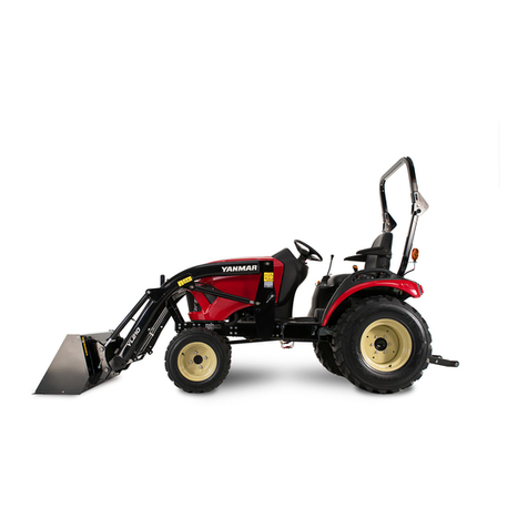
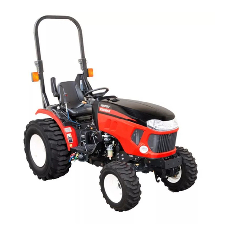
Yanmar EF-494T User manual

EF494T TM 06/2011 edition

EF494T TM 06/2011 edition
SAFETY
W
W
WA
A
AR
R
RN
N
NI
I
IN
N
NG
G
G
Never attempt to operate or service this machine until you have first read and
understood all of the applicable Safety Instructions that are set forth in this
Manual.
The failure to comply with all relevant Safety Instructions could result in bodily
injury.

TABLE OF CONTENTS TABLE OF CONTENTS
EF494T TM 06/2011 edition
i
TABLE OF CONTENTS
0 INTRODUCTION
To The Owner
MAINTENANCE
SUPPLY PERIOD FOR MAINTENANCE PARTS
IMPROVEMENTS
SYMBOL INDICATION
1
1
1
1
1
2
0.1 PRECAUTIONS FOR THE SAFE SERVICES
0.2 AFTER SALES SERVICE
0.3 GENERAL PRECAUTIONS FOR SERVICES
0.3.1 GENERAL
0.3.2 USAGE OF THE LIQUID GASKET
0.3.3 SCREW TIGHTENING TORQUE TABLE
0.3.4 FUSE BOX
0.3.5 PART NAMES
0.3.6 SAFETY LABEL LOCATION
0.3.7 SPECIFICATIONS
0.3.8 TRACTOR MASSAND TIRE SPECIFICATION
4
11
12
12
14
16
17
18
20
21
21
1 PERIODICAL INSPECTION
22
1.1 CHECK INTERVALS
1.2 OIL AND GREASE
1.3 OIL AND WATER VOLUME
1.4 EQUIVALENT TO TF-500
1.5 REPLACING OIL
1.6 REPLACING FILTER ELEMENTS
1.7 REPLACING COOLING WATER
1.8 REMOVING WATER FROM WATER SEPARATOR
1.9 CLEANING AND REPLACING AIR CLEANER
ELEMENT, CLEANING RADIATOR SCREEN
1.10 CHECKING BATTERY
1.11 CHECKING HOSE AND PIPE
1.12 CHECKING ELECTRICAL WIRING
1.13 GREASING
1.14 ADJUSTING BRAKE
1.15 ADJUSTING CLUTCH
1.16 ADJUSTING STEERING WHEEL
1.17 ADJUSTING FAN BELT
1.18 ADJUSTING TOW-IN
1.19 REPLACING FUSE
1.20 CHECKING TIRES
1.21 COLOR OF EXHAUST GAS
23
24
24
24
25
27
28
29
30
31
31
32
33
36
37
37
38
38
39
40
40

TABLE OF CONTENTS TABLE OF CONTENTS
EF494T TM 06/2011 edition
ii
2 DISASSEMBLY OF COMPONENTS
41
2.1 REMOVING THE ENGINE BONNET COVER
2.1.1 Removing/mounting the side covers
2.1.2 Removing the engine bonnet cover
2.2 REMOVING THE FENDER
2.2.1 Removing the fuel tank cover
2.2.2 Removing the nuts and bolts that fixing the fender
2.3 REMOVING THE STEP
2.4 REMOVING THE SEAT STAY
2.5 CLUTCH HOUSING
2.5.1 Separation
2.5.2 Docking
2.6 TRANSMISSION
2.6.1 Separating the hydraulic cylinder case
2.6.2 Separating the clutch housing and transmission
2.6.3 Rear axle
2.6.4 PTO module
2.7 FRONT AXLE UNIT
42
42
42
43
43
43
43
45
47
47
53
53
53
55
59
60
61
3 ENGINE
64
3.1 FUEL SYSTEM
3.1.1 Flow of fuel and layout of components
3.1.2 Water separator
3.1.3 Fuel feed pump
3.1.4 Fuel filter
3.1.5 Fuel injection pump (Type MP4 direct-injection
pump)
3.1.6 Fuel injection nozzles
3.2 COMBUSTION SYSTEM
3.2.1 Low emission technology applied to TNV engine
3.2.2 Cold starter
3.2.3 Revolution timer
3.2.4 Load timer
3.3 LUBRICATING OIL SYSTEM
3.3.1 Flow of lubricating oil
3.3.2 Lubrication oil pump (LO pump)
3.3.3 Lubricating oil filter (LO filter)
3.3.4 Oil pressure switch
65
65
66
66
66
66
67
68
68
70
71
71
72
72
73
74
74

TABLE OF CONTENTS TABLE OF CONTENTS
EF494T TM 06/2011 edition
iii
3.4 COOLING WATER SYSTEM
3.4.1 Flow of cooling water
3.4.2 Main components
3.4.3 Fuel injection pump
3.4.4 Piston
3.4.5 Checking pressures
3.4.6 Maintenance criteria
3.5 ADJUSTMENT SPECIFICATIONS
3.5.1 Engine adjustments
3.5.2 Cylinder head
3.5.3 Intake/exhaust valve and guide
3.5.4 Valve spring
3.5.5 Locker arm and shaft
3.5.6 Push rod
3.5.7 Camshaft
3.5.8 Idle gear shaft and bushing
3.5.9 Timing gear backlash
3.5.10 Cylinder block
3.5.11 Crankshaft
3.5.12 Thrust bearing
3.5.13 Piston
3.5.14 Piston rings
3.5.15 Connecting rod
3.5.16 Tappet
3.5.17 Lubricating oil pump (Trochoid pump)
3.5.18 Tightening torque tables
75
75
75
77
88
90
92
94
94
94
94
95
95
95
95
95
96
96
96
96
96
97
97
97
98
99
4 CLUTCH
100
4.1 STRUCTURE AND FUNCTIONS
4.1.1 Outline
4.2 DISASSEMBLY AND ASSEMBLY
4.2.1 Disassembly
4.2.2 Assembly
101
101
102
102
104
5 TRANMISSION
105
5.1 POWER TRANSMITTING DIAGRAM
5.2 TRANSMISSION SYSTEM CROSS-SECTION
5.3 TRANSMISSION SYSTEM
5.3.1 Main shift module
5.3.2 Reverse shift module
5.3.3 Range shift module
5.3.4 Front drive
5.3.5 PTO shift module
106
108
110
110
111
112
112
113

TABLE OF CONTENTS TABLE OF CONTENTS
EF494T TM 06/2011 edition
iv
5.4 TRANSMISSION (CLUTCH HOUSING CASE SIDE)
5.4.1 Disassembly
5.4.2 Main shift section
5.5 TRANSMISSION (TRANSMISSION HOUSING
CASE SIDE)
5.5.1 Disassembly
5.5.2 PTO module
114
115
120
121
123
128
6 REAR AXLE AND BRAKE
130
6.1 STRUCTURE AND FUNCTIONS
6.1.1 Structure drawing
6.1.2 Differential system
6.1.3 Final drive system
6.1.4 Brake
6.2 DISASSEMBLY AND ASSEMBLY
6.2.1 Differential system
6.2.2 Rear axle oil seal
6.2.3 Planetary gears and axle shaft
131
131
132
133
134
136
136
137
138
7 FRONT AXLE
139
7.1 STRUCTURE AND FUNCTIONS
7.2 CROSS-SECTION VIEW
7.3 FRONT WHEEL ALIGNMENT
7.4 DISASSEMBLING THE FRONT BEARING CASE
7.5 DISASSEMBLING THE FRONT GEAR BOX
7.6 DISASSEMBLING AND ASSEMBLING THE FRONT
DIFFERENTIAL SECTION
7.6.1 Disassembly
7.6.2 Assembly
140
141
142
143
143
144
144
146
8 POWER STEERING
148
8.1 STRUCTURE AND FUNCTIONS
8.1.1 Structure drawing
8.1.2 Hydraulic circuit
8.1.3 Power steering valve functions
8.1.4 Hydraulic pump
8.1.5 Power steering
8.2 POWER STEERING VALVE
8.2.1 Removing power steering valve assembly
8.2.2 Power steering relief pressure
8.2.3 Disassembly
149
149
150
151
152
153
154
154
155
156

TABLE OF CONTENTS TABLE OF CONTENTS
EF494T TM 06/2011 edition
v
9 HYDRAULIC LIFT UNIT
159
9.1 STRUCTURE AND FUNCTIONS
9.1.1 Hydraulic line
9.1.2 Hydraulic cylinder case
9.1.3 Control valve
9.1.4 Relief valve
9.1.5 Safety valve
9.1.6 Stop valve
9.1.7 Hydraulic pump, exploded view
9.1.8 Position feedback link
9.1.9 Oil flow
9.1.10 Oil flow at Neutral
9.2 ASSEMBLY AND CHECK
9.2.1 Assembling/disassembling the control valve
9.2.2 Control valve, exploded view
9.2.3 Main relief pressure
9.2.4 Adjusting the position feedback rod
9.3 HYDRAULIC POWER TAKE OFF
9.3.1 For single action, pump trailer etc.
9.3.2 For double action, front blade etc.
9.3.3 Hydraulic pressure flow
160
160
161
162
162
163
163
164
165
167
170
172
172
173
174
175
176
176
177
178
10 ELECTRIC EQUIPMENT
182
10.1 ENGINE START CIRCUIT
10.1.1 Location and operation of components
10.1.2 Circuit diagram
10.1.3 Checkpoints of electrical equipment
10.2 CHARGING CIRCUIT
10.2.1 Location and operation of components
10.2.2 Circuit diagram
10.2.3 Checkpoints of electrical equipment
10.3 ALARM CIRCUIT
10.3.1 Location and operation of components
10.3.2 Circuit diagram
10.3.3 Checkpoints of electrical equipment
10.4 SAFETY CIRCUIT
10.4.1 Location and operation of components
10.4.2 Circuit diagram
10.4.3 Checkpoints of electrical equipment
183
183
186
187
192
192
193
194
195
195
197
198
200
200
203
204

TABLE OF CONTENTS TABLE OF CONTENTS
EF494T TM 06/2011 edition
vi
11 APEENDIXES
206
11.1 HYDRAULIC CIRCUIT DIAGRAM
11.2 ELECTRICAL DIAGRAM AND PARTS
11.2.1 WIRING HARNESS
11.2.2 LOCATION OF ELECTRICAL PARTS
11.2.3 ELECTRICALWIRING DIAGRAM
207
208
208
209
210

0 INTRODUCTION 0 INTRODUCTION
EF494T TM 06/2011 edition
1
0. INTRODUCTION
To the owner of this manual
This machine is carefully designed and manufactured to give years of dependable service. To do
the better and safer job, read the instructions in this manual. Failure to do so could result in
personal injury or machine damage.
The parts used in this machine are subject to change to improve the quality and capacity of the
machine, and for safety.
Therefore, please understand that the contents, photos and illustrations in the manual may differ
from your machine.
MAINTENANCE
When the machine is in abnormal condition, take the remedies. If the machine is still abnormal, ask
Yanmar and give the following information:
Machine model
Serial number
Detailed description of abnormal condition
SUPPLY PERIOD FOR MAINTENANCE PARTS
The period during which we supply maintenance parts for this machine is 9 years after we discontinue
production of this machine.
The supply of maintenance parts will, in principle, terminate at the end of the supply period stated
above. However, even after the supply period has terminated, we still consult with you about the
delivery time and the prices for parts still in stock, if required.
IMPROVEMENTS
To improve or upgrade the feature of the machine or for some other reason, parts are sometimes
changed. In this case, parts of this manual may not apply to the machine.
The company has the right to improve or change when it becomes possible and practical to do so
without incurring any obligations to make changes or additions to the equipment sold previously.
NOTE:
(1) All data are subject to alteration without notice.
(2) Some photos, illustrations may not be identical with this machine due to improving or upgrading in
quality, performance or for some other reasons. Some illustrations and photos may show
optional accessories.
(3) Right-hand (R.H.) and left-hand (L.H.) sides of this machine are determined by standing at the
rear of this machine and facing the direction of forward travel.
0 INTRODUCTION 0 INTRODUCTION
EF494T TM 06/2011 edition
2
SYMBOL INDICATION
1 Safety-alert Symbol
This is the safety-alert symbol. When you see
this symbol on your tractor or in this manual,
personal injury is possible or even likely if you
do not follow the advice given. Read the
messages that follow carefully.
2 Signal Words
The signal words "DANGER" "WARNING"
"CAUTION" are used with the safety-alert
symbol.
(1) "DANGER" indicates the extreme hazard
that would result in high probability of
irreparable injury if proper precautions are
not taken.
DANGER
(2) "WARNING" indicates the hazard that
would result in injury if proper precautions
are not taken.
WARNING
(3) "CAUTION" indicates the general
precautions.
CAUTION
3 Service Instructions
(1) This stop symbol indicates an important
message about proper operation or
service. When you see this symbol, read
the message that follows carefully.
IMPORTANT
(2) NOTE describes precautions to take while
working.
NOTE
4 Measurements
This tractor is based on metric measurements.
All hardware is therefore metric (ISO). Make
sure to use the specified metric hardware when
service is necessary.
5 Direction
The right and left sides of the tractor are
determined by facing in the same direction as
the tractor moves when going forward.
DIRECTION

0 INTRODUCTION 0 INTRODUCTION
EF494T TM 06/2011 edition
3
WARNING
You must carefully note the length of the bolts when
you install Yanmar recommended implements and
equipment behind the transmission case.
1. First, it is necessary to measure the thickness of
the parts. Then use bolts whose length includes
the extra measured thickness.
2. When the original part is removed and a
different part is installed, it is necessary to
measure difference in thickness of the two parts
and change the length of the bolts appropriately.
If you don’t use appropriate consideration of these
issues, you will damage the transmission case and
create a dangerous situation.
Aluminum cases
Reference
The bolt length “B” in the case must be 2.0 times the
diameter of “A”.
For casting metal cases, rear axles, etc.,
The bolt length “B”in the case must be 1.5 times the
diameter “A”.
(D): Transmission case
Cast metal cases
When you install part “a” behind the
transmission case, use bolts whose length
includes measurement “C”.
CAUTION
Do not try to adjust engine speed adjuster screw
(A) located on engine fuel injection pump. Any
accident or failure resulting from adjusting the
screw would not be covered by Yanmar's
guarantee.
Do not try to unseal and adjust engine fuel
injection pump (B). Any accident or failure
resulting from adjusting the pump would not be
covered by Yanmar's guarantee.

0 INTRODUCTION 0 INTRODUCTION
EF494T TM 06/2011 edition
4
0.1 PRECAUTIONS FOR THE SAFE SERVICES
DANGER
SUFFICIENT VENTILATION
Be sure to work in the well-ventilated place when the engine
runs, welding or grinding a painted part.
[If not]
Exhaust gas and paint dirt is poisonous and hazardous
to human bodies.
CAUTION
FLAT PLACE AND SUFFICIENTAREA
The floor area should be sufficient, flat without holes at the
service factory (place) to perform check and service work.
[If not]
It may cause unexpected accidents such as falling
down.
CAUTION
CLEANED AND WELLARRANGED PLACE
Do not leave dust, mud, oil or any parts on the floor.
[If not]
It may cause unexpected accidents.
CAUTION
WELLAND SUFFICEINTLY LIGHTED PLACE
A working place must have enough lighting. Use a portable
safety light with cage when you work inside or under the
machine.
[If not]
The bulb may accidentally be broken and broken glass
may cause injury or heat may cause fire.

0 INTRODUCTION 0 INTRODUCTION
EF494T TM 06/2011 edition
5
CAUTION
KEEP A FIRE EXTINGUISHER AND FIRST AID KIT
HANDY
The workplace must be provided with a fire extinguisher.
Read instructions on the label to familiarize yourself with
how to use it.
Keep a first aid kit in a prescribed place.
Advise what to do in the event of fire or accidents.
Indicate who to contact in an emergency and keep their
telephone number in a prominent place.
CAUTION
WEAR PROPER CLOTHING AND SAFETY ITEMS
Do not wear loose clothing or jewelry that can be caught
on the control levers and other machine parts. Also
avoid wearing working clothes stained with oil as they
can ignite.
Be sure to wear a helmet, safety goggles, safety shoes,
a mask, gloves and other protective items, as
appropriate. Take particular precautions when
generating metal debris, when striking metal objects
with a hammer or when cleaning components with
compressed air.
Also make sure there are no persons near the machine.
[If not]
Moving part may catch, dust may get in eye, heavy part
may drop on foot, etc. It may cause serious injury.
DANGER
PROPER LIFTING AND SUPPORT
When you work under the machine, support it firmly with
such a crane, hoist or rigid racks on a level place.
[If not]
It may cause severe accidents.
CAUTION
PROPER TOOLS
Using damaged or worn tools or using tools inappropriate
for the required application is very dangerous, and may also
cause damage to the machine. Make sure to use the tools
that are appropriate for the specific job.
[If not]
It may cause severe injury and/or damages on machine.

0 INTRODUCTION 0 INTRODUCTION
EF494T TM 06/2011 edition
6
CAUTION
GENUINE PRODUCTS
Be sure to use and install genuine products and spare
parts.
[If not obeyed]
It may cause unexpected failures and shorten the
machine life span.
WARNING
TIGHTEN BOLTS AND NUTS WITH THE SPECIFIED
TORQUE
Be sure to tighten bolts and nuts with the specified torque in
this manual.
[If not]
Bolts or nuts may be loosen or drop. It may cause
breakdown of components and/or injury.
WARNING
AVOID SHORT-CIRCUITING
Be sure to disconnect the (-) terminal of battery before
servicing.
[If not]
Short circuit may cause a fire.
WARNING
CHARGING
BATTERY
Keep a battery away
from the fire while
charging. Gas from
battery electrolyte is
flammable and
explosive.
[If not]
It may explode or
cause fire.

0 INTRODUCTION 0 INTRODUCTION
EF494T TM 06/2011 edition
7
WARNING
HANDLING BATTERY ELECTROLYTE
The battery electrolyte is diluted sulfuric acid and
poisonous. Refill battery electrolyte in well ventilated area
and wear eye protection and rubber gloves.
[If not]
Splashed solution can cause burning skin, cloths and
blindness if it get into eyes.
DANGER
KEEP FUEL AND OIL AWAY FROM SOURCES OF
IGNITION
Open flames can ignite fuel, oil, hydraulic oil or
antifreeze solutions, which are flammable and
dangerous.
Special attention must be paid to the following matters.
Keep flammable materials away from lighted cigarettes
or matches, or any other sources of ignition.
Never refuel while the engine is running. Smoking
during refueling must be strictly prohibited.
Firmly tighten the caps on the fuel and oil tanks.
Store fuel and oil in a cool and well-ventilated place
where they are not subjected to direct sunlight.
Fuel and oil must be stored in a place which meets all
applicable safety regulations. Unauthorized persons
should not be allowed entry.
DANGER
PROVIDE ADEQUATE VENTILATION WHEN WORKING
IN AN ENCLOSED AREA
Engine exhaust fumes are harmful to the human body and
their inhalation is extremely hazardous.
When starting the engine in an enclosed area, open the
windows and doors for ventilation. Also do not idle the
engine unnecessarily or leave the engine running while the
machine is not in use.
DANGER
REMOVED ATTACHMENTS
When an attachment is placed on the ground or against a
wall after removing it or prior to reinstalling it, be sure that it
is stable to prevent it from falling down.

0 INTRODUCTION 0 INTRODUCTION
EF494T TM 06/2011 edition
8
DANGER
WORKING UNDER THE MACHINE
Before performing service or repairs underneath the
machine, place the implement on the ground in its
lowest position.
Be sure to apply blocks to the tracks to lock the tracks
securely.
Never perform service underneath the machine if it is
not completely stable.
DANGER
RADIATOR COOLING WATER LEVEL
Before checking the radiator cooling water level, stop
the engine and wait until the engine and the radiator
have cooled down.
Slowly loosen the cap to release the inner pressure
before removing the cap.
WARNING
BE CAREFUL OF HOT OIL UNDER HIGH-PRESSURE
Hydraulic fluid escaping under pressure can have
sufficient force to penetrate the skin and do serious
damage and that immediate medical assistance be
sought.
The hydraulic system for the implement operates under
high pressure.
When replenishing or draining hydraulic oil, be sure to
first relieve the high pressure.
The emission of hot oil under high-pressure from a small
leak could result in serious bodily injury.
Wear safety goggles and thick gloves when checking for
leaks. Use a piece of cardboard or a plywood block to
detect emissions of hot oil.
If the hot oil should contact your body, obtain prompt
medical treatment.

0 INTRODUCTION 0 INTRODUCTION
EF494T TM 06/2011 edition
9
WARNING
BE CAREFUL WHEN SERVICING SYSTEMS UNDER
HIGH TEMPERATURE AND HIGH PRESSURE
The engine cooling water and each lube oil system are still
under high temperature and pressure immediately after the
engine has stopped. Removing caps, draining oil and water,
or replacing filter elements at that time may cause a burn.
Wait until the temperature drops, then begin servicing in
accordance with the procedures described in this manual.
WARNING
ROTATING RADIATOR FAN AND FAN BELT
Never contact the rotating radiator fan or fan belt with
any object.
Contacting the rotating radiator fan or fan belt with any
object can result in serious bodily injury.
CAUTION
ALWAYS BE ENVIRONMENTALLY RESPONSIBLE
Follow the guidelines of the governmental agency for
the proper disposal of hazardous materials such as
engine oil, diesel fuel, engine coolant and, machine
fluid, grease.
NEVER dispose of hazardous materials irresponsibly by
dumping them into a sewer, on the ground, or into
groundwater or waterways.
Failure to follow these procedures may seriously harm
the environment.
Comply with legal regulations and guidelines for
disposal of: empty containers for fuel, cooling water
(coolant), oil, grease; fuel/oil filters; batteries; machine
itself; machine accessories; and packaging materials.

0 INTRODUCTION 0 INTRODUCTION
EF494T TM 06/2011 edition
10
WARNING
INFLATING TIRE
When you inflate tire, use long hose with self-attaching air
chuck for not standing in front of or over tire. Use safe cage
if available. Do not inflate tire beyond maximum
recommended pressure in operator's manual.
[If not]
An over-inflated tire can explode and cause injury or
death.
WARNING
MOUNT/DISMOUNT TIRE
Do not attempt to mount or dismount tire unless you have
proper equipment and experience. Follow proper procedure
when mounting or dismounting tire on wheel or rim.
[If not]
It may cause explosion and may cause injury.
WARNING
RIM OR RIM PARTS
Do not cut or weld on rim or rim parts. Do not use damaged
rims. If rim is damaged, replace it. Do not replace rims with
anything but a genuine or a part of proper size, type and
quality. Always deflate tire before removing spikes or other
objects from tire carcass.
[If not]
Damaged rim may cause an explosion.
AFTER SERVICING THE MACHINE MAKE SURE TO:
a) Retighten all removed fasteners, bolts and nuts to specified torque.
b) Reinstall all safety shields and devices removed during service.
c) Refill radiator coolant, hydraulic oil, engine oil, etc. which are drained during service with approved
or recommended fluid.
d) Start the engine and check for leaks. Operate all controls and make sure tractor and implements
are functioning properly. After testing, shut down the engine and check the work you performed
(any missing cotter pins, washers, locknuts, etc.) Recheck all fluid levels again.

0 INTRODUCTION 0 INTRODUCTION
EF494T TM 06/2011 edition
11
0.2 AFTER SALES SERVICE
After sales service
If your tractor is not working normally, refer to the
troubleshooting section in this manual. You can also
consult with your service representative.
Information needed when asking for service:
Model name and serial number (A) of your
tractor.
Engine type number (B)
Operating conditions. What type of work was
being performed when the problem occurred?
How long have you used your tractor? (total
hours of operation)
Any other information about the problem that has
occurred.
Availability of spare parts
Maintenance parts and spare parts will be available
for 10 years after the production of this tractor series
has been discontinued. However, special parts will
be available subject to consultation. Yanmar may be
able to supply a particular part after the normal
supply period.
(A) Tractor serial number
(B) Engine type number
(A)
(B)
PURPOSE OF THIS MACHINE
This machine is designed to be operated with a
various implement for particular tasks and for pulling
a trailer in a variety of agricultural operations. Other
use or modification is prohibited.

0 INTRODUCTION 0 INTRODUCTION
EF494T TM 06/2011 edition
12
0.3 GENERAL PRECAUTIONS FOR SERVICES
0.3.1 GENERAL
When contacting us about your machine identify it with the model and serial numbers of the tractor and
its engine, and the usage hours displayed on the hour meter.
Hour meter
The hour meter numerically indicates the operating
hours of the tractor. The indicated number is used
to determine when to check the engine oil and other
similar consumables. (The hour meter starts
counting when the engine is started.)
(A) Hour meter
WARNING
Prior to disassembly or reassembly, disconnect
battery cable (A) from the negative port (B) to
prevent short circuit.
To separate the transmission, be sure to lock
the front axle with the wedge (B) to prevent it
from swinging.
Other manuals for EF-494T
1
Table of contents
Other Yanmar Tractor manuals

Yanmar
Yanmar YM169 User manual

Yanmar
Yanmar EF-494T User manual

Yanmar
Yanmar SC 2400 User manual

Yanmar
Yanmar SA221 Operating manual

Yanmar
Yanmar YM276 User manual

Yanmar
Yanmar SA Series User manual

Yanmar
Yanmar EB3100 User manual

Yanmar
Yanmar YT235 User guide

Yanmar
Yanmar YM2000 User manual

Yanmar
Yanmar YM155d User manual
Popular Tractor manuals by other brands

Toro
Toro 8886 Operator's manual

Cub Cadet
Cub Cadet SERIES 5000 5252 Operator's manual

Southbend
Southbend Wheel Horse 604 Operation and Service Manual with Parts List

Simplicity
Simplicity 7100 Hydrostatic Series Operator's manual

Belle Group
Belle Group BMD 300 Operator's manual

Cub Cadet
Cub Cadet 1110 (293) owner's manual