Yaohua Weighing System XK3190-C601 User manual

XK3190-C601
WEIGHING INDICATOR
(BATCHING VERSION)
MANUAL
PLEASE READ THIS MANUAL VERY CAREFULLY
BEFORE OPERATING
Dec 2006
Specifications subject to change without prior notice

1
CONTENTS
1. GETTING STARTED
2. TECHNICAL PARAMETERS AND SPECIFICATIONS
3. LAYOUT AT FRONT AND DESCRIPTION
4. Parameter Setting and Calibration
5. INSTRUCTION FOR OPERATION
6. OPERATION ERROR CODES
7. APPENDIX
1. GETTING STARTED
CAUTION
•This is not a toy. Keep out of reach of children;
•This
indicator
is not an explosion proof device;
•This
indicator
is not a water proof device;
•Do not open this indicator, no user serviceable parts inside.
Always contact supplier for service.
1.1 Introduction
XK3190-C601 weighing indicator (batching version) adopts
MCS-51 SCM and high speed Σ– ΔA/D conversion method with
max.100 times/s conversion speed. It can make up batching scale
with load cell and other mechanical parts, applied in high speed
and high precision weighing control occasion.
1.2 Features
•Calibration and operation all by panel keys;
•With parallel printing interface connected to
stylus printer;
•Able to print out weighing records, accumulation
value and formula;
•Able to save/check/delete weighing records, data
protection at sudden power failure;
•With real clock, calendar;
•Able to set zero tracking range and auto/manual
zero range;
•Able to set A/D conversion speed and digital

2
filter intensity;
•With self-checking for input/output hardware
configuration and error code display function;
•With RS232 output(standard)or RS422 output
(optional),communicating with PC by continuously send mode
or command mode;
•With 20mA current loop output for connection of
scoreboard;
•With 4~20mA analog output(optional);
•With 6 inputs and 7 relay outputs to control max.
2 materials;
1.3 Connecting to Other Devices1
1.3.1 Connection to load cell
Connect thisindicator to load cell through the 9-pin load cell
connector located at the back. Refer to the below table for
load cell pin assignment.
① ② ③ ④ ⑤
⑥ ⑦ ⑧ ⑨
1Turn scale off and cut off power before making any connections or disconnections.
Short connect PIN 1 AND PIN 2, PIN 6 and PIN 7 when connected
to load cell with a 4-wire cable;
CAUTION
•Connection between load cell and indicator must be reliable;
shield-wire must be connected to ground reliably;
•Load cell and indicator are all
static-electricity-sensitive devices,measures must be
taken to ensure safety.
1.3.2 Connection to PC or SCOREBOARD or current display
(optional)
From the 15-pin interface located at the back, you could
•Connect indicator to computer via RS232 output or
RS422 output (optional);
•Connect indictor to scoreboard via 20mA current
loop output;
•Connect indicator to current display with 4~20mA
analog output.
.
15-pin connector
PIN # ASSIGNMENT
1 E-
2 S-
5 SHIELD
6 E+
7 S+
8 IN-
9 IN+

3
•Connect indicator to computer via RS232 output or
RS422 output (optional);
Data format for RS232 or RS422 is the same. Data is transmitted
in ASCII code. Data format is as listed below(one group):
1 2 3 4 5 6 7 8 9 10
START DATA STOP
There are two modes to communicate with PC:
•Continuously send, and
•Command mode.
A. Continuously send
Data transmitted is tare weight or net weight from the display
of the indicator. Each time it sends one frame data to pc, one
frame consists of 9 groups while the data format of one group
is as listed above. Below is the content for one frame:
For example,
Now the indicator displays 50.00KG, then the frame indicator
sends to PC is : =+0050.00;
If the indicator displays -0.040KG, then the frame indicator
sends to PC is : =-000.040;
B. Command mode
PIN # ASSIGNMENT PIN # ASSIGNMENT
1 RS422 OUTPUT+ 9 SCOREBOARD OUT+
2 RS422 OUTPUT- 10 SCOREBOARD OUT-
3 RS422 IN- 12 4~20mA I-
4 RS422 IN+ 13 4~20mA I+
6 RS232 RXD 14 CALIBRATION+
7 RS232 TXD 15 CALIBRATION-
8 GND
Note1: RS422 output is optional;
Note2: Function of short-connect pin 14 and pin 15 is as what
the calibration head performs.
Calibration head is a 15-pin connector with pin
14 and pin 15
s
hort connected which is usually packed together
with the manual.
G
ROUP
NO.
CONTENT NOTES
1 =START SIGNAL
2 +OR -SIGN SINAL
3 High digit
4 :
5 :
6 If decimal point is 3, then this group is “.”
7 If decimal point is 2, then this group is “.”
8 If decimal point is 1, then this group is “.”
9
WEIGHING
DATA
Low digit

4
Indicator will act according to instruction from computer,
please refer to following notes and table:
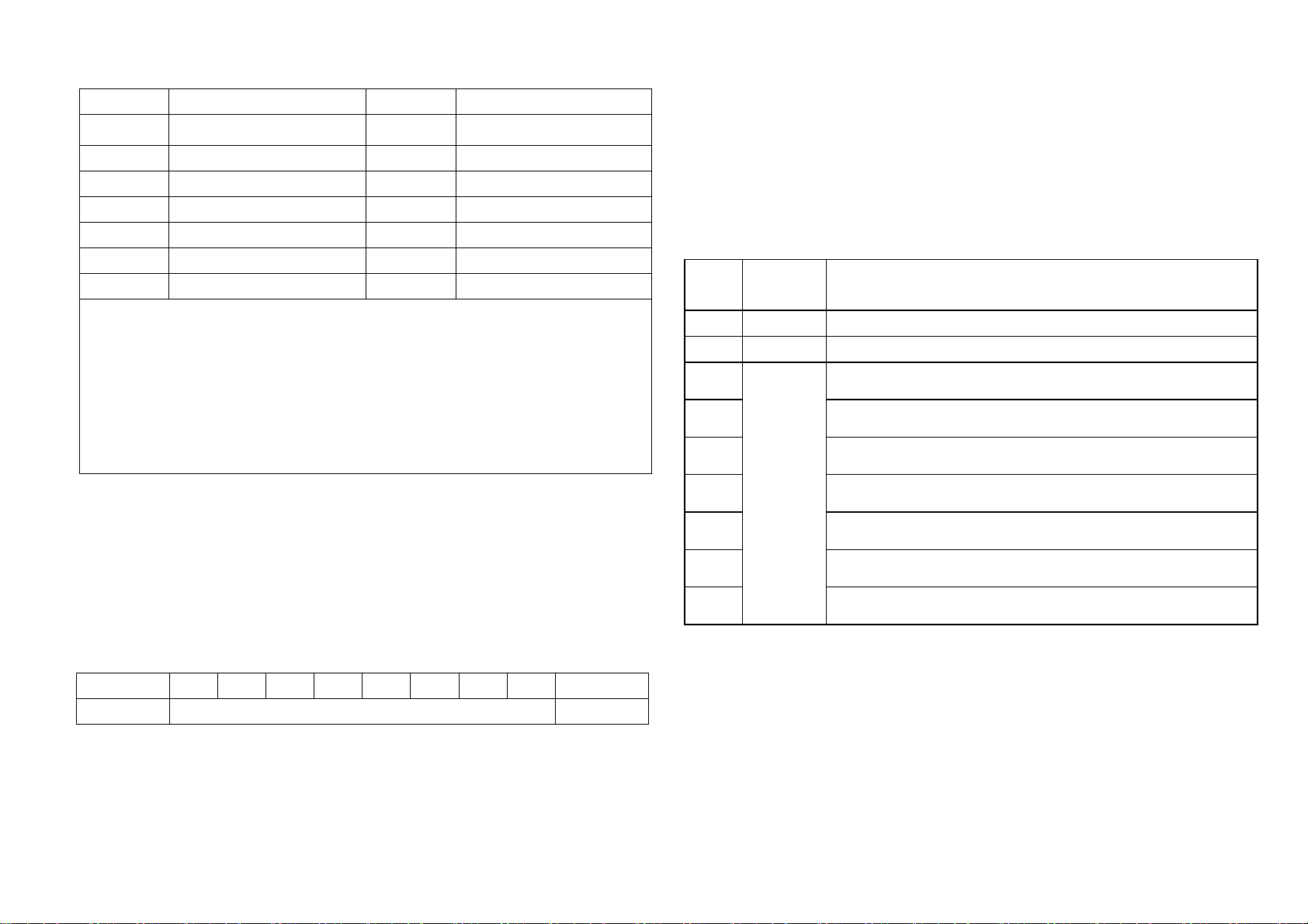
AD: address of indicator (example A in ASCII code 41);
NN: address of memory pc wants to read/write;
C1: Content pc wants to read/write (000 digit);
C2: Content pc wants to read/write (00 digit);
C3: Content pc wants to read/writ (0 digit);
XH: Verify result for high 4 digits;
XL: Verify result for low 4 digits;
Notes:
•Address indicator could set is from 1~26, while
communication address is corresponding from A~Z;
•Instruction from A~Z is transferred in ASCII code;
but the example listed in table is in Hex. code. When
communicating with PC via the hyper terminal software(This
software is with windows operating system),you should
choose “transmit in hex format”, or else you must convert
the example to ASCII code;
•Instruction Q,R,S,T U is read/write operation for
data memory. There are many strings in data memory, but
one instruction from pc only triggers one operation, hence
several instructions should be sent from pc one by one
to do these operations
Instruction table is listed in appendix
•Connect indictor to scoreboard via 20mA current
loop output;
Data is transmitted serially in binary code with baud rate 600.
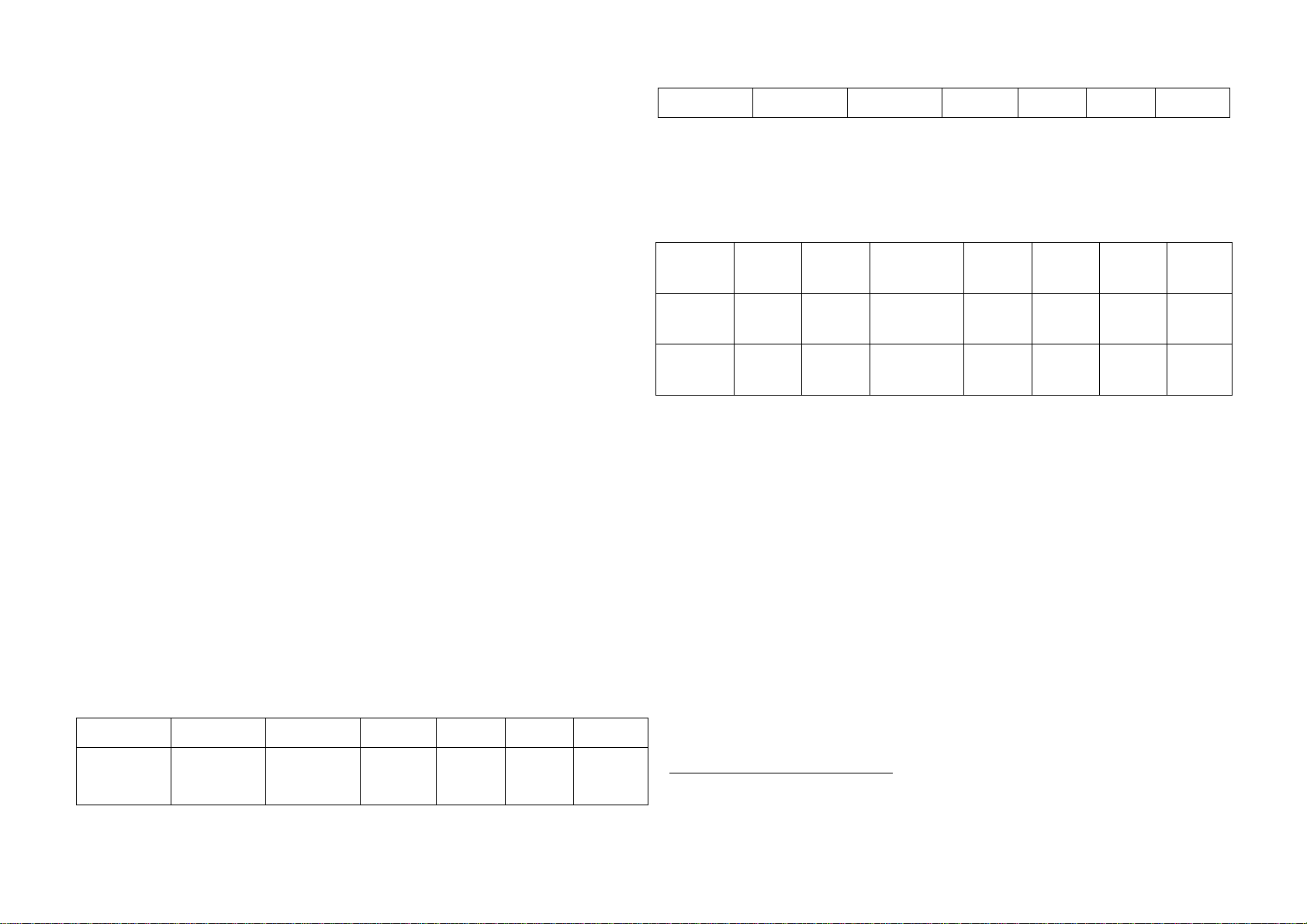
Data format is as listed below (one group):
0 1 2 3 4 5 6 7 8 9 10
START DATA(Low is prior to high) SIGN STOP
Indicator sends one frame data to scoreboard per 100ms, one
frame consists of 3 groups while the data format of one group
is as listed above. Below is the content for one frame:
0 1 2 3 4 5 6 7 8 9 10
D0 D1 D2 D3 D4 D5 D6 D7 SIGN STOP
G
roup
1 Start X Y G16 G17 0 1
0 1 2 3 4 5 6 7 8 9 10
D0 D1 D2 D3 D4 D5 D6 D7 SIGN STOP
G
roup
2 Start G8 G9 G10 G11 G12 G13 G14 G15 0 1
0 1 2 3 4 5 6 7 8 9 10
D0 D1 D2 D3 D4 D5 D6 D7 SIGN STOP
G
roup
3 Start G0 G1 G2 G3 G4 G5 G6 G7 1 1
For group one, Sign bit is 0; X(D0,D1,D2)means decimal point
(0~3); Y(D3)means sign(1 for negative while 0 for positive);
Y (D4) means display weight type( 1 for net weight while 0 for
tare weight); G17 and G16 is binary code;
For group two, Sign bit is 0; G15~G8 is binary code;

5
For group three, Sign bit is 1; G7~G0 is binary code;
From G0~G17 consists of 18 bit binary code, low prior to high.
with content of weighing data
•Connect indicator to current display via 4~20mA
analog output (optional)
When indicator is at zero,then current display will show 0;
when indicator is at the weight corresponding to 20mA, then
current display will show 20mA. (Refer to parameter setting
for how to set the weight corresponding to 20mA).
1.3.3 Connection with printer
25-pin interface
Description for each pin is as listed in above table. After
connect to stylus printer, indicator could print out weighing
records, accumulation value and formula.
1.4 Layout at the back of various interfaces
2. TECHNICAL PARAMETERS AND SPECIFICATIONS
•Accuracy: Class III,N=3000
•A/D Conversion Method: Σ– Δ
•Input Signal Range: 0mV ~ 15mV
•Net input signal range: 3mV ~ 15mV
•Nonlinearity: ≦0.01%FS
•Temperature rate at FS: ≦8PPM/℃
•Load Cell Excitation: DC5V, I =350mA
PIN # ASSIGNMENT PIN # ASSIGNMENT
1 ST 7 D5
2 D0 8 D6
3 D1 9 D7
4 D2 11 BUSY
5 D3 25 GND
6 D4

6
•Load cell connection mode: 6-wire mode, auto compensation
at long distance
•Display Digits: 6 x numeric bits and 1 sign bit with 0.5
inch character height plus 18 status indicators
•Division: 1/2/5/10/20/50
•Clock display: time and date display
•Key: 8 press keys with soft-touching PVC material
•Built-in 20mA current loop output for connection of
scoreboard
•Built-in RS232C output(standard) or RS422
output(optional) for connection of pc with selectable
baud rate and communication mode
•Built-in parallel printing interface for connection of
stylus printer
•Relay output: touching capacity at AC 220V,0.5A
•Input: Switch touching point (close effective)
•Operation Environment: 0o~40oC Non-condensed. R.H.
≦
90%
•Power Source: AC220V(-15%~+10%);50HZ(-2%~+2%)
3. LAYOUT AT FRONT AND DESCRIPTION
Key board:
[START] key
Press this key, then indicator start working in automatic
control status;
[STOP] key
Press this key, then indicator stop working in automatic control
status;
[ESC] key
Press this key to return to weighing status from parameter
setting status;
key
Press this key to
•enter into date/time setting mode or
•printing setting mode or
•accumulation value check mode or
•accumulation value clear mode or
shift to left digit when setting parameter value
key
Press this key to
•enter into calibration mode;
•shift to right digit when setting parameter value

7
key
Press this key to
•tare off the weight of a container when weighing display
is positive and stable;
•increase value at a digit when setting parameter value
key
Press this key to
•set weight displayed to zero;
•decrease value at a digit when setting parameter value
[ENTER] key
Press this key to confirm the current input by key;
INDICATORS AND PANEL
I1 INDICATOR
This is an input indicator. It will be on when [START] key is
pressed or when there is a short connect between pin 1 and pin
2 of control socket as listed in below table;
I2 INDICATOR
This is an input indicator. It will be on when [STOP] key is
pressed or when there is a short connect between pin 1 and pin
3 of control socket as listed in below table;
I3 INDICATOR
This is an input indicator. It will be on when there is a short
connect between pin 1 and pin 4 of control
socket as listed in below table. This input is usually given
when weighing indicator works in manual control mode to start
the charge control process.
I4 INDICATOR
This is an input indicator. It will be on when there is a short
connect between pin 1 and pin 5 of control socket as listed
in below table. This input is usually given when weighing
indicator works in manual control mode to start the discharge
control process.
I5 INDICATOR
This is an input indicator. It will be on when there is a short
connect between pin 1 and pin 6 of control socket as listed
in below table. This input is usually given when weighing
indicator works in manual control mode and after I3 input has
been given. Or it is usually given when weighing indicator works
in automatic control mode and after I1 input has been given,

8
be sure to keep this input always when working in automatic
mode and there is no required condition for charge material.
I6 INDICATOR
This is an input indicator. It will be on when there is a short
connect between pin 1 and pin 7 of control socket as listed
in below table. This input is usually given when weighing
indicator works in manual control mode and after I4 input has
been given. Or it is usually given when weighing indicator works
in automatic control mode and after o6 output has been given,
be sure to keep this input always when working in automatic
mode and there is no required condition for discharge material.
O1 INDICATOR
This is an output indicator. It will be on when weighing
indicator is at the process of fast feeding for the first
material.
O2 INDICATOR
This is an output indicator. It will be on when weighing
indicator is at the process of slow feeding for the first
material.
O3 INDICATOR
This is an output indicator. It will be on when weighing
indicator is at the process of fast feeding for the second
material.
O4 INDICATOR
This is an output indicator. It will be on when weighing
indicator is at the process of slow feeding for the second
material.
O5 INDICATOR
This is an output indicator. It will be on when weighing
indicator is at the process of discharging material.
O6 INDICATOR
This is an output indicator. It will be on when the weighed
material just reaches the OK range.2
O7 INDICATOR
This is an output indicator. It will be on when the weighed
material reaches out of the OK range. Usually under this
condition, customers should do something until it gives O6
output.
AUTO INDICATOR
2OK range is a weight range that customers could accept. Suppose the set
point for one material isA, minus or plus for this material customers could accept
is Q, then weight from A-Q to A+Q is OK range.

9
This is an indicator to indicate which working mode the weighing
indicator is at, if it’s auto mode, then auto indicator will
be on.
STABLE INDICATOR
This is an indicator to indicate a stable weight is being
displayed.
TARE INDICATOR
This is an indicator to indicate tare function is in operation
and net weight value being displayed;
ZERO INDICATOR
This is an indicator to indicate a net zero weight status.
TIME INDICATOR
This is an indicator to indicate current time is being
displayed.
Note: at back of the indicator, there is a 15-pin control socket
for input or output control
Pin 1 to Pin 7 is for input description:
Pin 7 Pin 6 Pin 5 Pin 4 Pin 3 Pin 2 Pin 1
Discharge
Permitted
Charge
Permitted
Discharge Charge Stop Start Public
I6 I5 I4 I3 I2 I1
When any of the pin from 2 to 7 is short connected to pin 1,
it just gives indicator one kind of input, corresponding input
I indicator will be on;
Pin 8 to Pin 15 is for output description:
Pin 15 Pin 14 Pin 13 Pin 12 Pin 11 Pin 10 Pin 9 Pin 8
12V NOT OK OK Discharge Slow 2 Fast 2 Slow 1 Fast 1
O7 O6 O5 O4 O3 O2 O1
When indicator is at the process of one of the statement,
corresponding output O indicator will be on.
There is a connection between this 15-pin control socket and
relay box with a cable offered by the supplier, when O indicator
is on, corresponding relay will work.
4.Parameter Setting and Calibration
4.1 Parameter setting3
There are three types of parameter to be set, they are:
[SET—0]: Parameter for check
[SET—1]: Parameter for configuration and function
3Calibration head must be put on to set parameter for [set-1] and [set-2], or else,
parameter value can’t be saved;

10
[SET—2]: Parameter for control
Key function description at parameter setting status as
followed:
•[↑][↓][←][→]:Shift between digits or increase value at
digit
•[STOP]: Return to last parameter setting
•[ESC]: Return to weighing status
[SET-0]:
Press [SET] key, it will display [set-0], then press [ENTER]
key, operate step by step refer to following table:
[SET-1]:
Press [SET] key, it will display [set-0], press [↑] key until
it shows [set-1], then press [ENTER] key, operate step by step
refer to following table:
40-not clear; 1-clear
50-No need for these connection; 1-need for these connection
6 Parameter A:0-outside code display; 1-inner code display
Parameter B: 1~8
B 1 2 3 4 5 6 7 8
(e) 0.5 1 1.5 2 2.5 3 3.5 4
Parameter C,D:0~5
C,D 0 1 2 3 4 5
F.S% 0 2 4 10 20 100
Item Display Parameter
description
Remark
1 [d**.**.**] Current date set Could set
2 [t**.**.**] Current time set Could set
3 [n ****] Accumulation time Check only
4 [A ******] Accumulation value Check only
5 [De1 0] Clear accumulation
value or not4
Press[ENTER],
finish
Item Display Parameter description Remark
1
[H ABCD] Hardware configuration5
A- PC connection
B- Scoreboard connection
C- Printer connection
D- Analog output
For example:
[H 1111]
2
[n ABCD] Zero parameter6
A-
O
utside code or inner
code display
B- Zero tracking range
C- Manual zero range
D- Auto zero range
For example:
[n 0222]

11
7E:
E 0 1 2 3
Times/s 12.5 25 50 100
The higher E is, the faster speed and less stability it will be
F:
F 0 1 2 3 4
Intensity Weaker weak Middle Strong Stronger
The higher F is, the more stability and more delay it will be
8When A of parameter H set as 0, parameterAdr,bt,tod is disabled;
[SET-2]:
Press [SET] key, it will display [set-0], press [↑] key until
it shows [set-2], then press [ENTER] key, operate step by step
refer to following table:
9When D of parameter H set as 0, parameter A****** is disabled; If D of H is set
as 1, then indicator will output 20mAanalog signal when it reaches the value
A****** set
3
[FLt EF] E-AD parameter setting7
E- AD sampling speed
F- AD filter intensity
For example:
[FLt 22]
4 [Adr **] Address for indicator8
(1~26)
5
[bt *] Baud rate(0~4)
0-600;1-1200;2-2400;3-48
00;4-9600
6
[tod *] Communication mode
0- Continuously send
1- Command mode
7 [Pt *]
8
[PL *] Printing language:
0- English
1- Chinese
9
[AtP *] Auto printing:
0- No auto printing
1- Auto printing
10
[A******]
2
0mA analog output weight
value set9
11 [Prt *]
T
o print above parameter set
value or not
0- No
1- Yes
Item Display Parameter description Remark
1
[C ABCD] Control parameter
setting10
For example:
[C 0101]

12
10 A: Plus or minus scale selection, 0-plus scale;1-minus scale
B: Ahead value auto correction selection,0-no correction;1-correction
C: Not OK range deal selection:0-not deal, continue cycle;1-wait until it
reaches ok range
D:Dot-makeup or not when it’s lack of weight,0-no;1-yes
Note: After calibration and these three-group parameters are
set, indicator could work properly.
4.2 Calibration15
Press [Calib] key, indicator will display [CALIb],it indicates
that it’s at calibration status. Press [ENTER] key, then
calibrate step by step as followed table:
11 One cycle is from charge to discharge, times is from 0~99 while 0 means
times is limitless
12 From t0 to t7, value set is from 0.0~9.9 seconds; always leave these
parameter as default setting, they are time to control the total process
more precisely
13 When D of C parameter set as 0, parameter t3 and t4 are disabled
14 Indicator will treat as discharge finish when tare weight is less than zero range
Print and accumulation will only function when tare weight is more than zero
range
15 Calibration head must be put on to save calibration data
2 [Pt 0] Cycle times11
3 [t0 **]12 Delay time before charge
4 [t1 **] Delay time at fast feed finish
5 [t2 **] Delay time at slow feed finish
6 [t3 **]13 Output time for dot-makeup
7 [t4 **] Output time for interval of dot-
makeup
8 [t5 **] Output time for OK range
9 [t6 **] Delay time at discharge finish
10 [t7 **] Delay time when next cycle begins
11 [L******] Zero range14
12 [A******] Set point for material 1
13 [b******] Ahead value for fast feed of material
1
14 [C******]
A
head value for slow feed of material
1
15
[d******] Q of ok range for material 1 Refer
to
Footno
te2
16 [P******] Set point for material 2
17 [q******] Ahead value for fast feed of material
2
18 [r******]
A
head value for slow feed of material
2
19 [t******] Q of ok range for material 2 Refer to
Footnote2
20 [Prt *] To print above parameter set value or
not
0- NO
1- Yes

13
5.INSTRUCTION FOR OPERATION
16 Ensure there is no load and stable indicator is on
5.1 Turning on
When indicator is powered on, it will display 0~9, then it comes
to weighing status. If the unloaded scale divates from zero
point but still within auto zero range, then indicator will
come to zero automatically;
Before Weighing
Make sure that:
a. The load cell signal cable is connected and properly
secured.
b. The scale is turned on.
5.2 Zero manually
If the unloaded scale divates from zero after auto zero when
turned on, but it’s still within manual zero range and the stable
indicator is on, press [ZERO] key, then indicator will come
to zero and zero indicator will be on;
5.3 Tare
At weighing status, when the current display is positive and
stable, press [TARE] key will tare off the current weight and
indicator will display 0, zero indicator is on
5.4 Date/time set
Press[SET] key, and then press [ENTER] key and set date, then
press [ENTER] key and set time.
5.5 Start/Stop
Item Display Parameter description Remark
1 [dC *] Decimal point(0~3) Press[ENTER]
after input
2 [E *] Division:1/2/5/10/20/
50
Press[ENTER]
after input
3 [F******] Full range Press[ENTER]
after input
4
[r 0] Keep former zero
0- Reconfirm current
zero
1- Skip zero
confirmation
I
nput 0,then go
to step
5(recommended)
I
nput 1, then go
to step 6
5 [noLoAd] Zero confirmation16
6
[AdLoAd] Load weight
P
ress [ENTER]
w
hen stable
indicator is on
7 [000000]
I
nput loaded weight
value
P
ress [ENTER]
after input
8 [******] Display current
weight value
Exit calibration
status

14
Press [START] key or short connect Pin 1 and Pin 2 as listed
above, indicator will enter into automatic control status;
press [STOP] key or short connect Pin 1 and Pin 3 as listed
above, indicator will exit automatic control status;
5.6 Manual work mode
When scale is ready for weighing, short connect Pin 1 and Pin
4 of control socket(Indicator I3 will be on),then short connect
Pin 1 and Pin 6 of control socket, (Indicator I5 will be on),then
it will start charge material. When the loaded material reaches
OK range, then short connect Pin 1 and Pin 5 of control
socket(Indicator I4 will be on),then short connect Pin 1 and
Pin 7 of control socket, (Indicator I6 will be on),then it will
start discharge material. This is one cycle in manual work mode.
5.7 Automatic work mode
When scale is ready for weighing, press [START] key or short
connect pin 1 and pin 2 of control socket to enter into automatic
control mode. Always short connect Pin 1 and Pin 6 of control
socket(Indicator I5 will be always on) if there is no required
for charge material, and indicator will begin charge
automatically. Always
short connect pin 1 and pin 7 of control socket(Indicator I6
will be always on)if there is no required for discharge material
only when O6 is on. Then after o6 is on, indicator will begin
discharge automatically. When indicator check that rest
material in the hooper is within zero range, it will begin the
next cycle automatically.
5.7 Input/Output hardware check
At inner code display status, user can check whether the
hardware of input/output connectors are good or not. When there
is input for I1, then O1 will be on; when there is input for
I2, then O2 will be on….when there is input for I6, then O1~O7
will be on. If O indicator is not on, then it’s not good.
6. OPERATION ERROR CODES
Err 1 Can’t meet requirement of tare
Err 2 Can’t meet requirement of zero
Err 3 Incorrect input for date/time
Err 4 EEPROM chip is damaged
Err P Printing cable is not connected or printer
error, print any key to exit
7. Appendix
Command Note Format Example
PC send handshake 02 AD 41 XH XL 03 02 41 41 30 30 03
AIndicator
send
handshake
02 AD 41 XH XL 03 02 41 41 30 30 03
B
PC send To read
02 AD 42 XH XL 03 02 41 42 30 33 03

15
gross
weight
Indicator
send
S
end gross
weight
02 AD 42 ** ** **
** ** ** ** ** XH
XL 03
0
2 41 42 2B 30 30
3
0 2E 30 30 30 30
36 03
PC send
To r
e
ad net
weight
02 AD 43 XH XL 03 02 41 43 30 32 03
C
Indicator
send
Send net
weight
02 AD 43 ** ** **
** ** ** ** ** XH
XL 03
02 41 4
3
2B 30 30
3
0 2E 30 30 30 30
37 03
PC send
To read
tare eight
02 AD 44 XH XL 03 02 41 44 30 35 03
D
Indicator
send
Send tare
weight
02 AD 44 ** ** **
** ** ** ** ** XH
XL 03
0
2 41 44 2B 30 30
3
0 2E 30 30 30 30
30 03
PC send To tare 02 AD 45 XH XL 03 02 41 45 30 34 03
E Indicator
send
Tare
02 AD 45 XH XL 03 02 41 45 30 34 03
PC send To zero 02 AD 46 XH XL 03 02 41 46 30 37 03
F
Indicator Zero 02 AD 46 XH XL 03 02 41 46 30 37 03
PC send To start 02 AD 47 XH XL 03 02 41 47 30 36 03
GIndicator
send
start
02 AD 47 XH XL 03 02 41 47 30 36 03
PC send To stop 02 AD 48 XH XL 03 02 41 48 30 39 03
H Indicator
send `
Stop
02 AD 48 XH XL 03 02 41 48 30 39 03
PC send To charge 02 AD 49 XH XL 03 02 41 49 30 38 03
IIndicator
send
Begin
charge
02 AD 49 XH XL 03 02 41 49 30 38 03
PC send
To
discharge
02 AD 4A XH XL 03 02 41 4A 30 42 03
J
Indicator
send
Begin
discharge
02 AD 4A XH XL 03 02 41 4A 30 42 03
PC send
To
Pause/Cont
inue
02 AD 4B XH XL 03 02 41 4B 30 41 03
K
Indicator
send
Pause/Cont
inue
02 AD 4B XH XL 03 02 41 4B 30 41 03

16
PC send
To
accumulate
02 AD 4C XH XL 03 02 41 4C 30 44 03
L
Indicator
send
Accumulate
02 AD 4C XH XL 03 02 41 4C 30 44 03
PC send To print 02 AD 4D XH XL 03 02 41 4D 30 43 03
M Indicator
send
Print
02 AD 4D XH XL 03 02 41 4D 30 43 03
PC send
To print
accumulati
on value
02 AD 4E XH XL 03 02 41 4E 30 46 03
N
Indicator
send
Print
accumulati
on value
02 AD 4E XH XL 03 02 41 4E 30 46 03
PC send
To print
formula
02 AD 4F XH XL 03 02 41 4F 30 45 03
O
Indicator
send
Print
formula
02 AD 4F XH XL 03 02 41 4F 30 45 03
P PC send
To print
calibratio
n rate
02 AD 50 XH XL 03 02 41 50 31 31 03
Indicator
send
Print
calibratio
n rate
02 AD 50 XH XL 03 02 41 50 31 31 03
PC send
To read
c
ontent of
calibratio
n rate
Q
Indicator
send
Send
c
ontent of
calibratio
n rate
02 AD 51 NN XH XL 03 02 41 51 30 32 30
03
PC send
To read
parameter
for
batching
02 AD 52 NN XH XL 03 02 41 52 30 32 33
03
R
Indicator
send
Send
parameter
for
batching
0
2 AD 52 NN C1 C2 C3
XH XL 03
0
2 41 52 30 30 30
30 31 33 03
S
PC send To read
02 AD 53 NN XH XL 03 02 41 53 30 32 32

17
accumulati
on value
03
Indicator
send
Send
accumulati
on value
02 AD 53 NN C1 C2 C3
XH XL 03
0
2 41 53 30 30 30
30 31 32 03
PC send
To write
c
ontent of
calibratio
n rate
02 AD 54 NN C1 C2 C3
XH XL 03
02 41 54 30 30 30
32 31 37 03
T
Indicator
send
Write
c
ontent of
calibratio
n rate
02 AD 54 NN C1 C2 C3
XH XL 03
0
2 41 54 30 30 30
32 31 37 03
PC send
To write
c
ontent of
calibratio
n rate
02 AD 55 NN C1 C2 C3
XH XL 03
02 41 55 30 32 35
35 31 36 03
U
Indicator
send
Write
c
ontent of
calibratio
02 AD 55 NN C1 C2 C3
XH XL 03
0
2 41 55 30 32 35
35 31 36 03
PC send
To clear
accumulati
on value
02 AD 56 XH XL 03 02 41 56 31 37 03
V
Indicator
send
Clear
accumulati
on value
02 AD 56 XH XL 03 02 41 56 31 37 03
PC send
To read
date
0
2 AD 54 NN C1 C2 C3
XH XL 03
02 41 54 30 30 30
32 31 37 03
W
Indicator
send
Send date
0
2 AD 54 NN C1 C2 C3
XH XL 03
0
2 41 54 30 30 30
32 31 37 03
PC send
To read
time
02 AD 58 XH XL 03 02 41 58 31 39 03
X
Indicator
send
Send time
02 AD 58 C1 C2 C3 C4
C5 C6 C7 C8 XH XL 03
0
2 41 58 30 34 3A
3
1 35 3A 32 36 31
44 03
PC send
To write
date
0
2 AD 59 C1 C2 C3 C4
C5 C6 C7 C8 XH XL 03
02 41 59 30 35 2D
30 37 2D 32 36 31
45 03
Y
Indicator Write date
0
2 AD 59 C1 C2 C3 C4
0
2 41 59 30 35 2D

18
send C5 C6 C7 C8 XH XL 03
3
0 37 2D 32 36 31
45 03
PC send
To write
time
02 AD 5A C1 C2 C3
C4 C5 C6 C7 C8 XH
XL 03
0
2 41 5A 30 39 3A
3
4 30 3A 32 36 31
32 03
Z
Indicator
send
Write
time
02 AD 5A C1 C2 C3
C4 C5 C6 C7 C8 XH
XL 03
Table of contents
Other Yaohua Weighing System Accessories manuals

Yaohua Weighing System
Yaohua Weighing System XK3190-A15 User manual

Yaohua Weighing System
Yaohua Weighing System XK3190 User manual

Yaohua Weighing System
Yaohua Weighing System XK3190-C602 User manual

Yaohua Weighing System
Yaohua Weighing System XK3190-A12 User manual

Yaohua Weighing System
Yaohua Weighing System XK3190-A12 User manual

Yaohua Weighing System
Yaohua Weighing System XK3190-A7 User manual

Yaohua Weighing System
Yaohua Weighing System YH-T6 User manual

Yaohua Weighing System
Yaohua Weighing System XK3190-A23p User manual