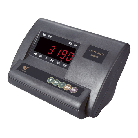
Yaohua Weighing System XK3190-C602 User manual

X K 3 1 9 0-C 602
XK3190-C602
Weighing Indicator
U
U
Us
s
se
e
er
r
r
M
M
Ma
a
an
n
nu
u
ua
a
al
l
l
(Version 1.03)
May 2009
Manufactured by Shanghai Yaohua Weighing System Co., Ltd.
No 00000071 Made in Shanghai

X K 3 1 9 0-C 602
Content
Preface
Chapter 1 General……………………………………………………
Chapter 2 Main Parameters……………………………………………
Chapter 3 Installation, Interface & Communication Format…………
Chapter 4 Parameters Setting and Calibration…………………………
Chapter 5 Operating Instruction of Quantitative Scale…………………
Chapter 6 Control Process of Quantitative Scale ………………………
Chapter 7 Operating Instruction of Catchweigher……………………………
Chapter 8 Application Examples of Catchweigher……………………………
Annex A Error Prompt Message……………………………………………
Annex B Schematic Diagram of Relay Board………………………………
Annex C Scoreboard Data Waveform Graph and Format………………
Annex D Data Format of Communication Port (1)…………………………
Annex E Data Format of Command-Response Mode of Communication Port (2)………………
Annex F Explanation on Print Format……………………………………
Annex G Troubleshooting of General Problems…………………………
Annex H Safety Instructions………………………………………………

X K 3 1 9 0-C 602
Preface
Instruction for use of manual
This manual is for reference by the operators and installers of XK3190-C602 indicator during
their operation or installation and testing. Chapter 1 and chapter 2 of this manual introduce the
technological features and parameters of the indicator in a general manner. Chapter 3 and chapter
4 describe the installation, parameter setting and calibration methods which can be referred to by
installers and repairmen as well as by on-site operators who need to adjust the working modes and
parameters of the indicator. Chapter 5 gives out the details of on-site operation methods when the
indicator is used to control quantitative scale. Chapter 6 explains the ways and working
procedures of the indicator when it is used to control quantitative scale, which can assist installers
and operators in understanding the setting of each parameter. Chapter 7 covers the on-site
operation methods of indicator when it is used to control catchweigher. Chapter 8 focuses on the
ways and working procedures of the indicator when it is used to control catchweigher, which can
help installers and operators understand the setting of each parameter. The annexes provide
information for error prompt message, communication format, and general problems.
During use of this manual, you may browse it first, and then select the contents related to
your current task while omitting the part not concerned. After you have got a general
understanding of the indicator, you can read it once again carefully.
The following glossaries are used in the manual:
Parameters are short for configuration parameters. The configuration parameters of quantitative
scale include the data setting of timing constant, batching value, and lead, while that of
catchweigher includes the data setting of timing constant and catch weight limit. Configuration
parameter 2 stands for the second set of parameters. Please note that only【SET 2】parameter can
be separately configured as 5 sets, while 【SET 1】can only have 1 set.
Lead During the feeding of quantitative scale, the weight of material on the load carrier is less

X K 3 1 9 0-C 602
than the weight of material delivered by the feeder since part of the delivered material is still in the
air and has not reached to the load carrier. To obtain the predetermined material weight, it is
necessary to turn off the feeder in advance. The weight involved in the leading is called a lead. For
C602, “self-correction of lead” function can be activated to ensure the accuracy of final weight.
Gradual feed When the feeding to quantitative scale is finished, the material weight is less than
the predetermined weight and the difference is beyond the tolerance, the indicator can start slow
feeding repeatedly and shortly to make the loaded weight approach to the predetermined value.
Add signal is short for “adding input signal is allowed”. Only when the add signal is valid can the
C602 output feeding control signal.
Discharge signal is short for “discharge input signal is allowed”. Only when discharge signal is
valid can C602 output discharge control signal.
Zero zone is the weight limit in additive scale which is used to judge whether the material in
hopper is completely discharged.
1. During discharging, it is deemed completed when the indicator shows the gross weight is
below zero zone.
2. The indicator can print and totalize only when the material weight is above zero zone.
For catchweigher, the self-control catchweigher can start weighing process only when the
weight signal is above zero zone and can print and sum when the calculation result of material
weight is above zero zone.
Additive scale is the quantitative scale used for batching control of added material weight in load
carrier (like hopper etc), for example, the hopper-type quantitative packing scale.
Subtracting scale is the quantitative scale used for batching control of subtracted material in the
load carrier (like hopper). It is also called weight loss scale.
Negative scale is the indicator to measure the weight removed from the load carrier. Subtracting
scale works as negative scale during feeding.
Channel is the range of object weight. C602 indicator can be divided into 5 weight ranges, also
called 5 channels. Each channel has 1 corresponding switch output signal.
Out-of-tolerance treatment When it is valid and the materials fed by quantitative scale is less
than the lower limit of batching value (subtracting tolerance of batching value), while there is no
gradual feed function, or when the fed material is more than the upper limit of set value (additive
tolerance of batching value), the quantitative scale will stop running, waiting for manual treatment.
When the weight meets the tolerance requirement, the quantitative scale will resume the
interrupted work.
Peak holding When the catchweigher captures an object weight, it will be displayed until the
X K 3 1 9 0-C 602
weight of next object is captured. The main display or auxiliary display can be selected to show
the captured object weight.
Initial zero-setting is the first zero-setting operation after startup. It can be set as automatic
zero-setting upon startup (initial) or manual zero-setting. If zero-setting upon startup is
prohibited, the indicator maintains the zero point at shutdown. The initial zero-setting range can
be selected and generally ±10%Max is set. If the variation of zero point of scale exceeds the
initial zero-setting range, initial zero-setting cannot be carried out. The zero-setting range
(generally ±2%Max) is based on the zero point determined during initial zero-setting.
Main display The 6-digit 0.56 LED digital tube in upper part of display window and the
indicators on both sides are main display of C602 indicator, which is used to display major
contents such as weight and set value etc..
Auxiliary display The 6-digit 0.4 LED digital tube in lower part of display window is auxiliary
display of C602 indicator, which is used to display accumulative value, summation, date, time,
operation procedure etc.. Parameters are prompted during parameter setting and error signal is
displayed in case of error prompt.

X K 3 1 9 0-C 602
Chapter 1 General
The XK3190-C602 weighing indicator adopts Cortex M3 32-bit processor and high-precision
Σ- A/D convertor to carry out conversion display for weight signal. The△maximum conversion
speed can reach up to 200/s. The display can be easily connected with resistance strain gauge
transducer to form batching scale and quantitative packing scale etc., suitable for various
applications where high-speed and high-precision weighing control are required.
Major functions and features of XK3190—C602 weighing indicator:
(1) Four optional working procedures of additive scale, subtracting scale, self-control
catchweigher and external control catchweigher. The catchweigher can be set as general
catchweigher and peak holding scale, with excellent versatility. As quantitative scale and
catchweigher, it can store 5 sets of parameters.
(2) AD speed can be set, and digital filtering intensity can also be set.
(3) Save, check, and delete weighing record, with power-off data protection function.
(4) Accurate clock, calendar, automatic leap year and leap month display, not affected by
power-off.
(5) Self-control function and various operation error messages.
(6) The standard configuration includes 8 optical isolation switch input, of which 2 channels
are used as high speed counting input, encoder input or interrupt (i.e. quick response) input; 8
optical isolation switch output (with external relay box optional). The standard program of
indicator can carry out batching value control for two materials.
(7) Expansion is possible for switch value input and output. With the connection of one
external IO expansion box, 8 additional switch input and 8 switch output can be provided. 4 IO
expansion boxes can be connected in series as a max..
(8) Two independent asynchronous serial communication interfaces, with interface 1 of
RS232 and interface 2 of RS232/RS422/RS485 optional. Two communication modes are available:
continuous send and command response.
(9) Parallel/serial print interface, available for connection with various printers.
(10) Chinese and English weighing record, accumulative value, parameters or calibration
parameters can be printed.
(11) Optical isolation 20mA current loop scoreboard display interface.
(12) 1 optical isolation 4 ~ 20mA/0 ~ 5V/0 ~ 10V analog output (optional).

X K 3 1 9 0-C 602
Chapter 2 Main Parameters
Indicator model XK3190—C602 weighing indicator
Precision degree Level 3
Max. verification scale
interval
nind=3000
Min. input signal voltage
of e verification scale
interval
1μV
Input signal range 3mV~15mV
Bridge power of weighing
load cell
DC:5V;80mA
Connecting type of
weighing load cell
6-wire system, automatic compensation
of long wire
Max. cable length of
weighing load cell
100m / 0.5mm2
Material: copper
Display Main display has 6-digit LED digital
tube, with character height of 0.56 in.
Auxiliary display has 6-digit LED digital
tube, with character height of 0.4"
23 status indicating lamps
Display scale interval 1/2/5/10/20/50 optional
0 ~ 3 decimal digits
Clock Yes. To show time and date
Keyboard Soft push switch is adopted, including 6
buttons.
Max. data memory
capacity
8064 weight data or 4032 groups of time
+ weight data
Scoreboard display
interface
Serial output is adopted. 20mA current
loop signal can be connected to various
sizes of scoreboard display of Shanghai
Yaohua Weighing System Co., Ltd.
Communication interface 2 serial RS232C, one of which can be set
as RS422/RS485

X K 3 1 9 0-C 602
Baud rate 600 ~ 57600bps optional.
Print interface Parallel output port: to be connected with
micro printer, LT800, KX-P1121 or
LQ1600K line printers.
Serial interface: to be connected with
serial interface printer
Switch output 8 optical isolation and open collector
switch output with max. control voltage
≤30V DC, current ≤100mA, total current
of 8 channels ≤200mA
Relay output (with relay
box)
Number of relay: 8
Contact capacity: 220VAC / 28V DC
0.5A
Switch input 8 optical isolation input, input signal +12
~ +24V DC, the pulse width shall be
above 0.2s
I0 and I1 can be configured as one of
four input modes: common input, 2
high-speed counting input, 1 decoder
input or 2 interrupt input, the maximum
counting frequency of high-speed
counting and coder input mode is
10KHz.
Expansion of Switch
input and output
Each expansion module has 8 optical
isolation input with input signal +12 ~
+24V DC
8 optical isolation relay output with
contact capacity 220V AC/28V DC
0.5A
The expansion module shall be provided
with stable external 12V power supply,
with maximum working current of
300mA
C602 indicator can be connected to 4
switch expansion modules as max..
Analog output Optical isolation output. It can be set as

X K 3 1 9 0-C 602
one of three modes 4-20mA / 0-5V /
0-10V.
Precision degree ≤0.2%FS
Load capacity:
4-20mA max. load resistor 250Ω
0-5V / 0-10V output impedance ≤1Ω
Working power supply 110~230V AC;50/60 Hz
Temperature and
humidity of working
environment
0℃~40℃;≤90%RH
Temperature and
humidity of
transportation and
storage
-20~50℃;≤90%RH
External dimension Housing: 150 * 75 * 105 (mm) (width *
height * depth)
Panel: 172 * 93 * 3 (mm) (width *
height* thickness)
Dimension of installation hole: 152 * 77
(mm)
Weight About 0.8kg

X K 3 1 9 0-C 602
Chapter 3 Installation, Interface & Communication Format
I. Schematic diagram of front panel and back panel of indicator
Figure 3-1 Schematic Diagram of Front Panel
Indicating lamp for
operating status
Indicator lamp
for output
Display window Indicator lamp
for weighing
Keyboard Indicator lamp
for input
il

X K 3 1 9 0-C 602
Figure 3-2 Schematic Diagram of Back Panel
Connecting
terminal of power
Connecting terminal of
switch output
Connection
terminal of switch
Connection terminal of
analogue output
Calibration
switch
Connecting
terminal of
Interface of
parallel printer
Connection terminal
of weighing load cell

X K 3 1 9 0-C 602
II. Schematic diagram of main panel and power panel
Figure 3-3 Schematic Diagram of Main Panel
IO expansion
socket
Expansion
socket
JTAG interface
Socket of AD
module
ISP jumper or toggle
switch
RS232/RS485
optional jumper
Inter-panel

X K 3 1 9 0-C 602
Figure 3-4 Schematic Diagram of Power Panel
Inter-panel
connector
High voltage area
in power panel
Setting jumper of
analogue output

X K 3 1 9 0-C 602
Attention: the indicator shall have sound and reliable earthing
protection so as to ensure the operation stability and safety of
operator.
Installation method of indicator
Unscrew two M4 fastening screws on both sides at back of the indicator, remove the binding,
insert the indicator into the installation hole, insert the binding again and fasten it with M4 screws.
Disassembly and assembly of indicator
When changing analogue output mode or RS422/RS485 upper and lower resistance or the
terminating resistance, the indicator should be opened to adjust the position of corresponding
jumper at the main board or power panel. Please carry out the disassembly and assembly of the
indicator according to following method to avoid any damage.
Attention: many elements in the indicator are sensitive to static electricity. Please get rid
of charge in human body before disassembling the indicator by touching wall or other
earthed object so as to protect the indicator against damage by static electricity.
Disassembly method: remove all screws in back panel of indicator, remove the back panel,
carefully draw out the upper power panel and the lower main board to adjust corresponding
jumper.
Assembly method: carefully insert the main board and power panel into the slots in the
housing. When it is about to be fully inserted, and encounters significant resistance, as if blocked
by something, at this time, do not insert it forcedly, instead, shake the circuit board and carefully
insert it. If fails, check whether the contact pin of connector is deformed and whether there is any
abnormity in double socket in the display panel. When circuit board is inserted to its place, mount
the back panel and fasten all screws. Please note that the screws in the four corners are
self-tapping screws and the rest are M3 * 6 SL screws.

X K 3 1 9 0-C 602
III. Connection between load cell and indicator
1. 7-pin electrical male plug are adopted for connection of load cell. Figure 3-5 shows the
meanings of each pin.
2. When junction box is used to connect several load cells or extend the cable of load cell,
six-wire connecting method must be adopted. When 1 load cell is used and the cable is not
extended, four-wire system can be adopted. Under this condition, it is necessary to short connect
the EX+ and SEN+ with EX- and SEN- respectively.
3. The load cell and indicator should be reliably connected and the shielded line of load
cell should be reliably connected with GND terminal. The connecting line can not be plugged
in and out when the indicator is powered on in order to prevent any damage to the indicator
or load cell by static electricity
4.The load cell and indicator are both static sensitive equipments, so anti-static measures
must be taken during the use. It is strictly forbidden to carry out welding operation or other
operations with high current on the weighing platform. In the stormy season, lightening
prevention measures must be taken reliably to prevent any damage to load cell and indicator
caused by lightening stroke, and to guarantee the personal security of operators and safe
running of weighing devices and relative equipments.
In the figure: EX+, EX-: excitation power supply; SEN+, SEN-: excitation feedback; SIG+, SIG-: load cell output
signal; GND: shield
Figure 3-5 Connection Diagram of Load cell

X K 3 1 9 0-C 602
IV. Printer interface
1. Parallel printer interface adopts the standard 25-pin D type jack socket. Figure 3-6 shows
the meaning of each pin. The indicator can be connected to printer by standard parallel
interface printer cable. The 13th pin is +5V output which can be used to connect micro printer
with peak current below 2A.
Figure 3-6 Printer Interface
2. Serial printer interface uses the communication interface RS-232 (1). See RS-232 (1) in
(Fig. 3-7) for the meaning of each pin. Busy means the printer is busy.
Setting of printer
Correctly set the parameters 7, 8, and 9 (see table 4-3 in chapter four) of 【SET 1】according
to the printer model and printing language (Chinese or English). If the printer not listed in the
table is to be used, try to select the model with similar printing command format with those listed
in the table.
Selection of micro printer
It is suggested to adopt the mirco printer with Chinese library, available for printing at least 16
English charanters in 1 line. When micro printer without Chinese character database is used, only
English printing mode is available for selection.
The micro printer shall support the following commands:
Switch to Chinese printing: ESC 8 n (0x1b, 0x38, n)
Reverse printing: ESC C n (0x1b, 0x63, n)
Our company can select the micro printer for customers, which has been verified in the C602.
11 10 9 8 7 6 5 412 2
3 113
23 22 21 20 19 18 17 1624 14
1525
BUSY D7 D6 D5 D4 D3 D2 D1 D0 ST
信号地
+5V
Signal ground

X K 3 1 9 0-C 602
V. Scoreboard display interface
The scoreboard display interface is the 20mA current loop interface which is capable of
driving various scoreboards produced by Yaohua.
Please refer to appendix C for the data format and oscillograph of scoreboard display interface.
In the figure, DP+ and DP- are the 20mA current loop interface of scoreboard.
Figure 3-7 Serial Communication and Scoreboard Display Interface
VI. Serial communication interface (1)
Serial communication interface (1) is RS232C interface which is capable of transmitting AD
switch code or weight data to the PC at high speed, the data rate is equal to AD switching speed.
The function of serial interface (1) can be set by 【SET 1】parameter 6Aand its baud rate can be
set by 【SET 1】parameter 5A. Refer to appendix D for data format.
Serial interface (1) can also be used as the drive interface to connect the serial interface
printer. The XOFF/XON flow control protocol can be adopted and Busy signal can be used to
control the transmission of printing data.
VII. Serial communication interface (2)
Serial communication interface (2) can transmit data to PC as well as receive control
command issued by the PC and set parameter. Serial communication (2) can communicate with
PC by selecting continuous send or command response. The function of serial interface (2) can
be set by 【SET 1】parameter 6Band its baud rate can be set by parameter 5B.
The factory setting of serial communication interface (2) is RS232C, and it can be
automatically set as RS422/485 interface. The jumper JP4 chooses different positions based on the
selection of RS232 or RS422/484. See figure 3-5 for the connection of communication interface,

X K 3 1 9 0-C 602
in which the right RxD and TxD are RS-232 (2) interface while the TXD0, TXD1, XD0, and
RXD1 are RS422/485 interface. Only one of the two can be selected in operation. If terminating
resistance and pull-up resistance or pull-down resistance needs to be connected, open the housing,
draw out main panel, and short jumper JP3 in main panel. When 1-2 are shorted, the pull-down
resistance is valid, when the 3-4 are shorted, terminating resistance is valid, and when 5-6 are
shorted, the pull-up resistance is valid. If RS485 communication mode is used, please short TXD0
and RXD0, TXD1 and RXD1 terminals respectively. Parameter【SET 1】6Bmust select 2. At
this time, the communication interface is working in command response mode to prevent the
conflict of bus. The range of common-mode voltage of RS422/RS485 mode is ≤±7V.
1. Continuous send mode
When 【SET 1】parameter 6Bis set as 1, continuous send mode is active. See table 3-1 for
data format. All data are ASCII code, each byte is made up of ten bits, with the first bit as the
start bit and the tenth bit as the stop bit, the bits in between are data bits, no check bit is available.
The transmitted data are the current weight value (gross weight or net weight) measured by the
indicator, each frame has 9 bytes. See table 3-1 for format.
Table 3-1 Communication Format of Continuous Send Mode of Serial Interface (2)
Byte Content Explanation
1 G or N G stands for gross weight while N for
net weight.
2 =Start bit
3 Weighing data
Most significant bit, non-significant
zero is represented by space, the same
with the following
4 Weighing data Data or symbol
5 Weighing data Data or symbol
6 Weighing data Data or symbol
7 Weighing data
If there are three bits of decimal, this
byte is “.”.
8 Weighing data If there are two bits of decimal, this
byte is “.”.
9 Weighing data
If there is one bit of decimal, this byte
is “.”.
10 Weighing data Least significant
b
it, it is a space i
f
there is no decimal.
11 0x0D Carriage return

X K 3 1 9 0-C 602
For instance, if the indicator measures a gross weight of 50.00 (kg), it will send data as
follows:
“G=50.00”;
If the indicator measures a net weight of -0.040 (kg), it will send data as follows:
“N=-0.040”.
2. Command response mode
When 【SET 1】parameter 6Bis set as 0 or 2, the serial interface 2 works in command
response mode. If serial interface 2 works in continuous send mode, when the PC sends correct
command to the indicator in command response mode, the indicator will automatically switch to
command response mode. If the PC does not send read in EEPROM command, C602 will still
work in continuous send mode after next startup. With regard to response mode, the PC sends
“setting the communication mode into continuous send mode”, the indicator will switch to
continuous send mode.
Please refer to appendix E for the communication format of command response mode.
12 0x0A Linefeed sign

X K 3 1 9 0-C 602
VIII. Control interface and indicating lamp
See figure 3-8 for optical isolation switching value interface. O0 ~ O7 are the switch output
signal terminals for the 8 open collectors, with each terminal absorbs current 100mA at
maximum and the total current shall not exceed 200mA. I0 ~ I7 are the 8 Switch input signal
terminals. 0V and +12V are the connecting terminals for 12V external isolation power supply,
with maximum capacity of power supply of 200mA. The output terminal can be directly
connected with the cable terminal of relay box which is supplied with the C602 indicator to
transform the output mode of C602 into relay output. The signal input terminal of indicator can
connect with +12 ~ +24V voltage as compared with 0V terminal, it can also be shorted with
+12V to be effective signal. Attention: the 0V terminal on back panel is isolated from the
indicator housing and weighing load cell interface GND terminal. The input and output status
indicating lamps on the indicator panel display the actual status of input and output terminals.
Terminal mark +12V O7 O6 O5 O4 O3 O2 O1 O0 I7 I6 I5 I4 I3 I2 I1 I0 0V
Definition of
quantitative
scale terminal
12Vpo
wer
supply
positiv
e
O
u
t-
o
f-
t
o
l
e
r
a
n
c
e
q
u
a
li
fi
e
d
f
e
e
d
i
n
g
S
l
o
w
f
e
e
d
2
Q
u
i
c
k
f
e
e
d
2
S
l
o
w
f
e
e
d
1
Q
u
i
c
k
f
e
e
d
1
Z
e
r
o
p
o
si
ti
o
n
S
t
a
n
d
b
y
D
is
c
h
a
r
g
e
si
g
n
a
l
A
d
d
i
n
g
si
g
n
a
l
D
is
c
h
a
r
g
e
F
e
e
d
i
n
g
st
o
p
Oper
a
t
ion
Standby 12Vpower supply negative
Table of contents
Other Yaohua Weighing System Accessories manuals

Yaohua Weighing System
Yaohua Weighing System YH-T6 User manual

Yaohua Weighing System
Yaohua Weighing System XK3190 User manual

Yaohua Weighing System
Yaohua Weighing System XK3190-A15 User manual

Yaohua Weighing System
Yaohua Weighing System XK3190-A23p User manual

Yaohua Weighing System
Yaohua Weighing System XK3190-A12 User manual

Yaohua Weighing System
Yaohua Weighing System XK3190-A12 User manual

Yaohua Weighing System
Yaohua Weighing System XK3190-C601 User manual

Yaohua Weighing System
Yaohua Weighing System XK3190-A7 User manual