YARMEE YC837 User manual

DIGITAL CONFERENCE SYSTEM
YC837

1
INSTRUCTION MANUAL
With the multiple-conference is more and more popularization, the requesting of the meeting
equipments are higher for the multi-functional meeting room, it need the function of video camera
auto-track, voting, electing and interpretation in lots of the discussion meeting situation. Our company
developed the multi-functional meeting control system on the base of summarizing the experience of
multiple-conference and speaking system for many years.
This system designed by the latest digital technology in accordance with IEC914 and ISO standards.
It’s a high effective Multi-functional meeting system for a meeting or conference, and it’s easy to
setting-up, debugging and using without training.
Part A. System Configuration
Conference system main unit (Built-in discuss & video), chairman unit, delegate unit, interpreter unit,
high-speed dome, software, software Dongle, video display card, and computer, etc.
★Main unit
1. Power consumption of main unit 400W, each unit can support 60 units delegate and chairman
microphone, it could be extended to support 200 units microphone by adding more Extension
machines
2. This system can work with computer or without computer. User can select the system manage
mode on the front panel of main unit: PC manage mode and main unit manage mode.
3. Main unit has following features when work without computer
a. LCD display the working mode on the front panel
b. Support many conference work mode: Free, FIFO (1-9 microphone unit), Limit (1-9
microphone unit).
4. Main unit has following features when work with computer and other equipments
a. Manage the meeting with software, support double screen display
b. Voting function (yes, no abstain)
c. Electing function (single-ballot and Multiple-ballot)
d. Audience response (100, 75, 50, 25,0)

2
e. Internal Video camera auto-track function
f. System can support following discuss work mode: Free mode, FIFO mode (1-9 microphone
unit), Limit mode (1-9 microphone unit)
5. Power supply:AC220V 50/Hz
6. Installation:19-inch frame
7. Connection:
8. ---1pcs 13m main cable with 8PIN plugs.
9. ---8PIN socket for system connection.
Schematic diagram of main unit
1.(POWER)
2.(MODE):FREE,FIFO(1~9), LIMIT(1~9), Panel mode,PC mode
3.(NUMBER),( 1~9)
4.(SAVE)
5.LCD
6.(MIC)
7.(AUX)
8.(MONITOR)
9.(MASTER)
10.(UNIT.VOL)
11.(VIDEO INPUT 1-8)
12.(VIDEO OUTPUT 1-2)
13.(RS-232)PC PORT
14.(RS-232)VIDEO DOME
15.(INDICATOR)
16 (RS-422 / RS-485)

3
17.(TREBLE GAIN)
18. (AUX IN)
19. (LINE、REC)
20. (BAL OUT)
21. (MIC IN)
22. (EFX OUT / IN)
23. (DELEGATES)
24.(DATA)
25.(AC220V)
★Microphone unit
1) Newly digital design
2) Listening and speaking
3) The system power supply for all the delegate units is provided by the main unit at 24 safe voltages.
4) With 8-PIN T-type hand-in-hand interconnection cable
5) Built-in high fidelity speaker and earphone jack.
6) Electric capacity type microphone.
7) Extended pipe optional.
8) Volume control of each microphone independently.
9) The annular red indicator lamp could show the state of the microphone.
10) The chairman unit number in the system is unrestricted, can join in any position of the system.
11) Chairman can turn down delegate MIC by priority button,
12) Indicative sound for chairman unit (optional)
13) C. only mode: only chairman microphone can be turn on.
14) Earphone output jack and wireless microphone input jack for chairman unit (optional)

4
Computer manage software
1. This system software must used on window.
2. Need one RS-232 port for control computer
3. Auto calculate the result when voting, and automatically contrast result pass or not with the
pre-setting condition
4. Can display the conference information and result on the projector screen or TV
5. Can insert words or marks during the conference processing
6. Can download conference information to the computer for saving or printing
7. All setting can be finished in the pre-setting state in the central processor when using the camera.
After setting, download the data and can manage the video camera tracking function in the following
conference processing
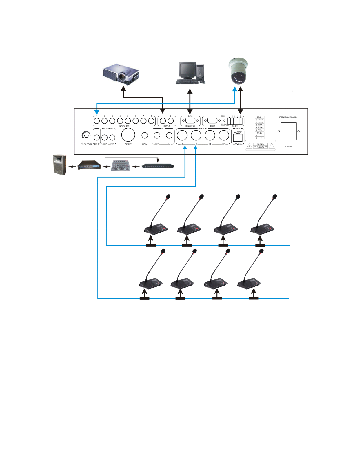
Part B. System connection and debug
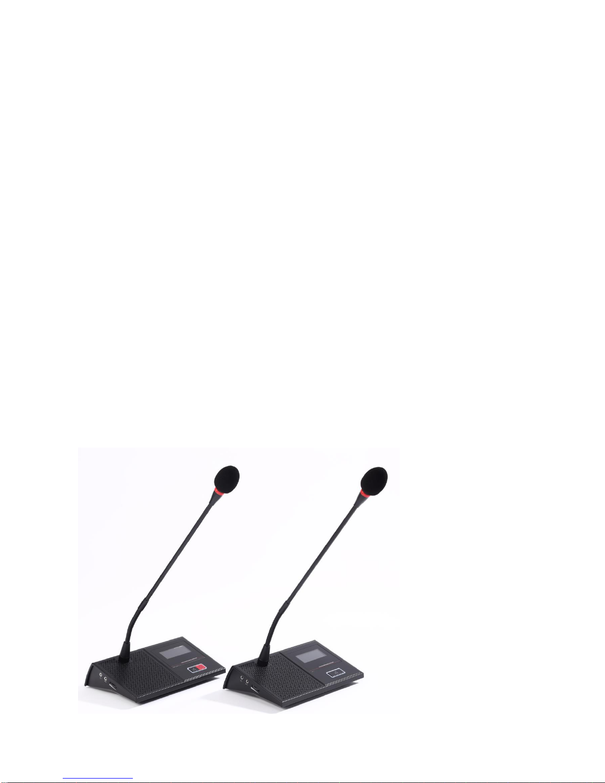
1. Put conference main unit and microphone to the council board.
2. Please connect RS-232 interface of main unit to RS232 interface of computer.
3. Connect the dome data cable to DATA port of main unit.
4. Install the conference software in the computer.
5. Install the video display card to the computer, the installation and setting method is in software
manual.
6. Connect projector or TV to computer ( when with vote function)
7. Please connect the male plug of extension cable (13M) to 8PIN port (marked DELEGATES) of
the main unit.
8. Please connect male plug of T type main cable to the female plug of extension cable, branch
cable connect to the 8PIN port of the microphone.
9. Connect the microphone by branch cable one by one in the system.
10. Please embedding the cable in the ground if the cable should not be saw in the meeting room.
(we will make the cable with size of conference projector drawing)
11. Please connect the EFX out port to balance input port of frequency shifter by audio cable,
connect the EFX in port to balance output port of frequency shifter by audio cable.
12. Please connect mixer to output port of main unit if user use mixer.
13. Please connect the amplifier to LINE port of main unit
14. Please connect the speaker to the amplifier.
15. Please connect the recorder to REC port of main unit
16. After connect the system well, turn off the power of the system (the main unit) and debug the
main unit volume (VOL.) to minimum position, other volume control to middle position.
17. Connect the power cable to the main unit and Power supplier, and then turn on the main unit to
check the power indicator.
18. Turn on one microphone; debug the volume by VOL control in the front panel of main unit to
make sure the system volume is suitable for speaking and listening.
19. Please test the function of main unit one by one first.
20. System working mode setting: Press MODE key of the main unit, the LCD will display the mode:
Free, FIFO, Limit, Host and PC mode. Please press SAVE key after user select the mode and
microphone number, then the LCD will display the system work mode one the LCD after save
the data.

5
1). Host mode:
a. Press MODE key to select “Host mode” on the LCD.
b. Press SAVE key to save the setting
c. Press MODE again to select the working mode: FREE, FIFO, LIMIT mode.
d. Press SAVE key to save the setting, if user selects FIFO or LIMIT mode, then continue to set
the number, if select FREE mode, then the setting is finished.
e. Press MODE key to LCD display NUMBER, and press number key to set the number (1-9).
f. Press SAVE key to save the setting
2). PC mode:
a. Press MODE key to select “PC MODE” on the LCD.
b. Press SAVE key to save the setting.
c.After setting the pc mode, please test the system with software.
★Technical Data
Model
Data
Main unit
Microphone unit
Voltage
AC220V
DC24V
(Supply by 8PIN cable)
Power
consumption
400W
2W
T.H.D.
〈0.05%
〈0.05%
Dimension
480X330X90mm
205X150X55mm / MIC pipe 450mm
S/N
〉75db
〉75db
Control port
RS-232 interface
Sensitivity
-56dB Wire microphone
-44dB ±2dB
Frequency
response
40Hz——16KHz
40Hz——16KHz
Weight
Kg
0.9Kg
Color
Grey
Gray
Installation
19-inch unit
Removable
We remain the right to modify any issue without notice in advance

6
★Schematic diagram
Table of contents
Popular Conference System manuals by other brands

AT&T
AT&T MERLIN LEGEND MLX-10 Non-Display Telephone user guide

AT&T
AT&T MERLIN LEGEND Release 2.0 Single-Line... user guide

Autani
Autani EnergyCenter autaniNet/EnOcean Bridge quick start guide

Grand Won
Grand Won GRANDHUB manual

Polycom
Polycom VSX 3000 quick start

David Clark
David Clark U9912-BSW user manual

Polycom
Polycom SoundStructure C16 Hardware installation guide

COMMUNICATIONS-APPLIED TECHNOLOGY
COMMUNICATIONS-APPLIED TECHNOLOGY ICRI-E Setup and operating procedures

Bosch
Bosch INTEGRUS Installation and operating manual

Worldcast Systems
Worldcast Systems APT IP Quick Start Notice

Studer
Studer Xcom-GSM quick guide

LaserBit
LaserBit PICO Plus Series user manual