manuals.online logo
Brands
  1. Home
  2. •
  3. Brands
  4. •
  5. YASKAWA
  6. •
  7. Control Unit
  8. •
  9. YASKAWA Varispeed f7 User manual

YASKAWA Varispeed f7 User manual

Sales and Service Network in Europe and Worldwide
European Headquarters
Yaskawa Electric Europe GmbH
Am Kronberger Hang 2
65824 Schwalbach - Germany
Tel.: +49 (0) 6196-569300
Fax: +49 (0) 6196-569398
EMail: [email protected]
www.yaskawa.de
France
Yaskawa Electric Europe GmbH
Z I des Béthunes
2, rue du Rapporteur
95310 St Ouen L’Aumône
France
Tel.: +33 (0) 1-39 09 09 00
Fax.: +33 (0) 1-30 37 29 02
UK
Yaskawa Electric Europe GmbH
Unit 2, Centurion Court
Brick Close, Kiln Farm
Milton Keynes
Bucks MK 11 3JA
UK
Tel.: +44 (0) 1908-565874
Fax.: +44 (0) 1908-565891
www.yaskawa.co.uk
Italy
Yaskawa Electric Europe GmbH
Via Emilia Ovest 95/F
41013 Castelfranco E. (MO)
Italy
Tel.: +39 (0) 59-922121
Fax.: +39 (0) 59-922168
www.yaskawa.it
Spain
Yaskawa Electric Europe GmbH
Errekalde etorbidea, 59
20018 Donostia San Sebastian
Spain
Tel.: +34 943-360832
Fax.: +34 943-360193
www.yaskawa.es
UK
Yaskawa Electric UK Ltd.
1 Hunt Hill, Orchardton Woods
Cumbernauld G68 9LF
United Kingdom
Tel.: +44 (0) 1236-735000
Fax.: +44 (0) 1236-458182
Worldwide Headquarters,
Japan, Tokyo
Yaskawa Electric Corporation
New Pier Takeshiba South Tower
1-16-1, Kaigan, Minatoku
Tokyo 105-6891
Japan
Tel.: +81 (0) 3-5402 4511
Fax.: +81 (0) 3-5402 4580
www.yaskawa.co.jp
Singapore
Yaskawa Electric (Singapore) PTE. Ltd.
151 Lorong Chuan, #04-01
New Tech Park Singapore 556741
Singapore
Tel.: +65 282 3003
Fax.: +65 289 3003
Shanghai
Yaskawa Electric (Shanghai) Co., Ltd.
4F No. 18 Aona Road
Waigaoqiao Free Trade Zone
Pudong New Area
Shanghai 200131
China
Tel.: +86 21 5866 3470
Fax.: +86 21 5866 3869
Korea
Yaskawa Electric Korea Corp.
Kfpa Building#1201
35-4 Youido-Dong
Yeongdungpo-Ku
Seoul 150-010
Tel.: +82-2-784-78 44
Fax.: +82-2-784-84 95
American Headquarters
Yaskawa Electric America Inc.
2121 Norman Drive South
Waukegan, IIlinois 60085
USA
Tel.: +1 847-8877000
Fax.: +1 847-8877370
www.yaskawa.com
Brasil
Yaskawa Electrico do Brasil
Avenida Fagundes Filho, 620-Saude
Sao Paulo – SP Brasil
CEP 04304-00
Tel.: +5511 5071 2552
Fax.: +5511 5581 8795
European Headquarters
Yaskawa Engineering
Europe GmbH
Am Kronberger Hang 2
65824 Schwalbach - Germany
Tel.: +49 (0) 6196-569520
Fax: +49 (0) 6196-888598
EMail: [email protected]
www.yaskawa.de
YEG-KAE-S616-55B Printed in Germany 4/2002
Feature 1:
Precise control, functionality and flexibility
Feature 2:
Ecologically friendly
Feature 3:
User-friendly installation
and operation
Reliable energy saving function
The energy-saving control approches the maximum efficiency. Highly-efficient,
energy-saving operations are realized for any application using either the vector
control or the V/f control.
Low noise operation
With the low noise carrier PWM control for heavy duty mode as well as with the high
carrier PWM control for normal duty mode a considerable quiet motor operation is
achievable.
Suppression of harmonic distorsion
All inverters whith an output power of 22 kW and higher have a double diode
supply, for 12 pulse input, which makes it possible to suppress the harmonics to
about 12%. They are also equipped with a built-in DC bus reactor. For the inverters
below 22 kW the DC bus reactor is available as option.
Note: 12-pulse input requires a special transformer
Main Features of Varispeed F7 Inverter
High grade and good concentricity
Yaskawa's open loop vector control allows an excellent torque characteristic at a
speed ratio of 1:100. Hence at 0.5Hz, for example, more than 200% of the rated
torque is available.
Three autotuning functions
• The proven autotuning function with motor rotating (no load) during
measurement.
• New method which wieds similarly good result with motor at a standstill.
• Measurement of the motor resistance for simple applications.
High slip braking (HSB)
Yaskawa’s intelligent function allows up to 3 times faster braking without the use of a
braking transistor or resistor.
Braking transistor
This transistor is built in as standard in inverters of up to 18.5kW,
and is available as an external option for higher outputs. In conjunction with an
external braking resistor it achieves very powerful braking.
Improved protective functions
The high speed overcurrent limiting function allows virtually uninterrupted operation (no overcurrent tripping, restart
after momentary power loss, motor stall prevention, attempted restart after malfunction, etc).
CASE (Custom Application Software Environment)
makes it easy to customize the Varispeed F7 to the user or application requirements if they are not covered by the extensive
standard functions.
Speed search function
The Varispeed F7 determines the speed and direction of rotation of a coasting motor, then brings it to the required reference
speed. This is carried out extremely smoothly in both directions.
Easy to operate
• The Varispeed F7 can be fully controlled using the digital operator. The
operator is equipped with a parameter copy function and can even be
used up to 3m away with a standard cable. The LED display can be
read easily, even at a considerable distance.
• An optional LCD operator with plain text in 7 different languages and
the same functions is available.
Clear hierarchy of menus for setting parameters
Easy operation for fast start up and maintenance.
Quick program
Simplifies the start-up procedure by showing the most important para-
meters only.
Modified Parameters
Easy troubleshooting by checking the parameters modified from the
factory defaults.
Easily maintained
• The control terminal block can be disconnected from the motherboard.
This enables replacement of the inverter without disconnecting the
controlwiring.
• The inverter fan switches off when the motor is at a standstill. If neces-
sary, it can be replaced without dismantling the unit.
Feature 4:
Global specification
CE mark
for Europe UL mark for Canada and the USA
250
200
150
100
50
0
Motor torque [%]
0.5 1.5 3 10
Motor torque [%]
Operating frequency [Hz]
Conformity with global standards for
worldwide use
Certified to UL/cUL and CE
Available worldwide
Worldwide service
Operation with commonly
used mains voltages
• Series for 400V (three phase)
380 to 480V +10% -15%
• Series for 200V (three phase)
200 to 240V +10% - 15%
Global fieldbus standards
supported
• RS-485/422 (MEMOBUS protocol)
supported as standard
• Optional cards available for Profibus-DP,
INTERBUS-S, CANopen and DeviceNet
(LONworks, CC Link & ControlNet)
Mains current
without suppression
of harmonic distorsion
Mains current with
12 pulse method
(%) 100
80
60
40
20
0 20 40 60 80 100 (%)
Damper control at 60Hz
Control with Varispeed F7
Load
Econimic efficiency
CUS
LISTED
Description
of digital operator
Overview of display and keypad
Varispeed F7
Varispeed F7
Data display
Menu button
Switches menu within
the hierarchy.
Local/Remote button
Changes over from control
with the digital operator to
control via the terminal block.
JOG button
Enables RUN with JOG speed,
which has highest priority.
FWD/REV button
Reverses the direction of
rotation of the motor.
Arrow up
button
Increases the parameter
number or data value.
Arrow down
button
Decreases the parameter
number or data value.
Digital operator
Status LEDs
One of these comes on to indicate
the inverter status.
ESC button
Returns to previous menu in the
hierarchy without saving.
Enter button
Saves parameter setting data.
Entering a parameter number in the
PRGM mode displays the associat-
ed data.
Reset button
Shifts the digit of a value that is
selected to be changed resets
operation when a fault has occured
(ecknowledgement)
Stop button
Stops the motor.
Run button
Starts the motor. The LED in the
top left corner of the button lights
up on to indicate that the motor is
running.
CIMR – F7C40P41
Inverter
Varispeed F7 series
No. Rated output of motor
0P4 0.55 kW
4P0 4.0 kW
7P5 7.5 kW
011 11 kW
045 45 kW
110 110 kW
160 160 kW
300 300 kW
Code Power supply
2three phase 200V AC
4three phase 400V AC
Code Protection
0IP00
1NEMA1/IP20
Specification/Nameplate
Code Specification
AJapanese standard
CEuropean standard
UAmerican standard
The radio interference filters tested by Yaskawa are listed below. The stipulations of the Operating Manual (YEG-TOE-S616-55.1) or
separate EMC documentation relating to their connection must be followed to achieve proper electromagnetic compatibility (EMC).
Radio interference suppression filters for conformity with the EMC Directive (CE)
DC reactor (optional) Braking resistor unit (optional)
+ 1 + 2 –B1 B2
S1
S2
S3
S4
S5
S6
S7
SN
U/T1
V/T2
W/T3 M
shielded cable shielded twisted pair cable
MP
AC Pulse train output
AM
FM
AC
AM
FM
20kΩ
20kΩ
Current display
Multi-functional analog output 1
Multi-functional analog output 2
(-10 to +10V 2mA/4 to 20mA)
E(G)
MA
MB
MC
M1
M2
M3
M4
M5
M6
Fault contact output
During Run
Zero speed
Frequency
agree 1
Multi-functional output digital output
(250V AC, 1A 30V DC, 1A)
0V
-V -15V 20mA
R+
R-
S+
S-
IG
Memobus communication
RS-485/422
2kΩ
2kΩ
+V -15V 20mA
A1 Analog input 1
A2 Analog input 2
AC
-10…+10V
4…20mA
RP Puls train input
E(G)
+24V
R/L1
S/L2
T/L3
Forward Run/Stop
Reverse Run/Stop
External fault
Fault reset
Multi-step speed
setting 1
Multi-step speed
setting 2
Jog frequency
selection
Multi-functional digital
inputs
SC
SP
Standard connection diagram for Varispeed F7
Dimensions
WxHxD (mm)
Current
(A) Weight
(kg)
Inverter model Filter model Fit under
yes/no
CIMR-F7C20P4
CIMR-F7C20P7 FS 5972-10-07 10 1.1 141x330x46 yes
CIMR-F7C21P5
CIMR-F7C22P2 FS 5972-18-07 18 1.3 141x330x46 yes
CIMR-F7C23P7
CIMR-F7C25P5 FS 5973-35-07 35 1.4 141x330x46 yes
CIMR-F7C27P5 FS 5973-60-07 60 3 206x355x60 yes
CIMR-F7C2011
CIMR-F7C2015 FS 5973-100-07 100 4.9 236x408x80 yes
CIMR-F7C2018
CIMR-F7C2022
CIMR-F7C2030 FS 5973-130-35 130 4.3 90x366x180 no
CIMR-F7C2037 FS 5973-160-40 160 6 120x451x170 no
CIMR-F7C2045 FS 5973-240-37 240 11 130x610x240 no
CIMR-F7C2055
CIMR-F7C2075
CIMR-F7C2090 Filters under development no
CIMR-F7C2110
CIMR-F7C40P4
CIMR-F7C40P7
CIMR-F7C41P5 FS 5972-10-07 10 1.1 141x330x46 yes
CIMR-F7C42P2
CIMR-F7C43P7
CIMR-F7C44P0
CIMR-F7C45P5 FS 5972-18-07 18 1.3 141x330x46 yes
CIMR-F7C47P5 FS 5972-21-07 21 1.8 206x355x50 yes
CIMR-F7C4011 FS 5972-35-07 35 2.1 206x355x50 yes
CIMR-F7C4015
CIMR-F7C4018 FS 5972-60-07 60 4 236x408x65 yes
CIMR-F7C4022
CIMR-F7C4030 FS 5972-70-52 70 3.4 80x329x185 no
CIMR-F7C4037
CIMR-F7C4045 FS 5972-100-35 100 4.5 90x326x150 no
CIMR-F7C4055 FS 5972-130-35 130 4.7 90x366x180 no
CIMR-F7C4075 FS 5972-170-40 170 6 120x451x170 no
CIMR-F7C4090 FS 5972-250-37 or 250 11.7 130x610x240 no
CIMR-F7C4110 FS 3359-250-28 250 7.0 230x300x125 no
CIMR-F7C4132 FS 5972-400-99 or 400 18.5 300x610x160 no
CIMR-F7C4160 FS 5972-410-99 410 10.5 260x386x115 no
CIMR-F7C4185 FS 5972-410-99 410 10.5 260x386x115 no
CIMR-F7C4220 FS 5972-600-99 600 11 260x386x135 no
CIMR-F7C4300 FS 5972-800-99 800 31 300x716x160 no
Line
Filter
Main contactor
Fuse
L1
L2
L3
PE
3-phase power supply
380 to 480 V
50/60 Hz
Figure 2
Dimensions:
(IP20 protection) (IP00 protection)
Figure 1
Standard specifications
*1: The recommended maximum connected load is specified for a four pole standard motor. Choose the version of the inverter that does not exceed
the rated current of the motor.
T
3
B 1 4-d
B
H 1
H 2
H 0
H 3
H
4
T 1
t1
B1
H 1
H
H2
t1
4-d
B T(5) (5)(5) T1
Varispeed F7
Varispeed F7 Varispeed F7
Varispeed F7
Voltage class
Inverter model CIMR-F7C
Recommended maximum
motor output (kW) *1
Rated output (kVA)
Rated current (A)
Max. output voltage
Max. output frequency
Rated input voltage and
frequency
Suppression
of harmonic
distorsion
DC bus
reactor
Double diode
12 pulse supply
Inverter
output
Mains input
200 V
20P4 20P7 21P5 22P2 23P7 25P5 27P5 2011 2015 2018 2022 2030 2037 2045 2055 2075 2090 2110
0.55 0.75 1.5 2.2 3.7 5.5 7.5 11 15 18.5 22 30 37 45 55 75 90 110
1.2 1.6 2.7 3.7 5.7 8.8 12 17 22 27 32 44 55 69 82 110 130 160
3.2 4.1 7 9.6 15 23 31 45 58 71 85 115 145 180 215 283 346 415
three phase 200 to 240V (proportional to input voltage)
150Hz in constant torque mode, 400Hz in variable torque mode
three phase, 200 to 240V, 50/60Hz
Optional Built in
not available Standard
Voltage class
Inverter model CIMR-F7C
Recommended maximum
motor output (kW) *1
Rated output (kVA)
Rated current (A)
Max. output voltage
Max. output frequency
Rated input voltage and
frequency
Suppression
of harmonic
distorsion
DC bus
reactor
Double diode
12 pulse supply
Inverter
output
Mains input
400 V
40P4 40P7 41P5 42P2 43P7 44P0 45P5 47P5 4011 4015 4018 4022 4030 4037 4045 4055 4075 4090 4110 4132 4160 4185 4220 4300
0.55 0.75 1.5 2.2 3.7 4 5.5 7.5 11 15 18.5 22 30 37 45 55 75 90 110 132 160 185 220 300
1.4 1.6 2.8 4 5.8 6.6 9.5 13 18 24 30 34 46 57 69 85 110 140 160 200 230 280 390 510
1.8 2.1 3.7 5.3 7.6 8.7 12.5 17 24 31 39 45 60 75 91 112 150 180 216 260 304 370 506 675
three phase 380 to 480V (proportional to input voltage)
150Hz in constant torque mode, 400Hz in variable torque mode
three phase, 380 to 480V, 50/60Hz
Optional Built in
not available Standard
General specifications
from -15 to +10%
from -5 to +5%
Sinusoidal pulse width modulation (open loop current vector control, V/f control,V/f control with pulse generator)
1:100 (open loop vector control)
±0.2% (25 ±10°C) (open loop vector control)
Digital reference: 0.01Hz, analog reference: 0.025/50Hz (11-bit plus sign)
0.01 Hz
4 to 20mA (250Ω), -10 to +10V (20kΩ),pulse train input
0.01 to 6000 seconds (4 different independent acceleration and deceleration times)
about 20% without braking resistor, about 125% with braking resistor,(braking chopper built in up to and including 18.5kW)
Fully user-definable
Electronic thermal overload relay (PTC evalution possible)
150% of inverter ratet current for 1 min. in heavy duty mode,120% of inverters rated current for 1 min in normal duty mode
Fault tripping occurs if the DC bus voltage exceeds 410V with a 200V, or 820V with a 400V inverter
Fault tripping occurs if the DC bus voltage drops to a value less than 190V at 200V inverters,or 380V at 400V inverters
Operation can be continuet if the power supply is restored within 2 sec
Controlled by thermistor
Stall prevention during acceleration and deceleration, and operation can be set separately
Protection provided by electronic circuit
The charging indicator lights up if the DC bus circuit voltage exceeds 50V
Seven inputs, of which 5 are fully user-definable with 48 different functions
1 change over contact for fault/ready signal; 3 NO contacts fully user-definable with 35 different functions
1 analog input -10V to +10V, 1 analog input -10V to +10V or 4 to 20 mA, 1 pulse train input,user defibable
2 analog outputs –10 to +10V, switchable to 4 to 20mA with 22 different functions,
1 user-definable pulse train output
5-character, 7-segment display,12 LED status indicators for forwards/reverse, local/remote control, alarm, ready, status of short menu,
standard menu, modified parameters, autotuning, start, stop.
9 buttons for displaying and programming the parameters and changing the speed, RUN button and STOP button
Copy and verify function included
An LCD digital operator with plain text in 7 languages and the same functions as the LED operator is available as an option
IP20 up to and including 18.5kW, IP00 (IP20 optional) from 22kW
Maximum of 95% (non-condensing)
IP20 inverters from -10 to +40°C, IP00 from -10 to +45°C
From -20 to +60°C (short-term in transit)
Indoors (rooms free from corrosive gases and dust)
Maximum of 1000m
Maximum of 9.8m/s2(1g) from 10 to 20Hz, maximum of 2m/s2(0.2g) from 20 to 50Hz
Allowable mains
voltage fluctuation
Allowable mains frequ. fluct.
Control method
Speed control range
Frequency accuracy
Resolution of
frequency setting
Output frequency resolution
Reference frequency signal
Acceleration/deceleration time
Braking torque
V/f characteristic
Motor protection
Overload
Overvoltage
Undervoltage
momentary power loss
Overheating of heat sink
Stall prevention limit
Earth fault
DC bus charging indication
Digital inputs
Digital outputs
Analog inputs
Analog outputs
Displays
Buttons
Copying function
Option
Case
Relative humidity
Ambient temperature
Storage temperature
Installation location
Height of installation location
Vibration
MainsControl/regulationProtective functions
Inputs and
outputs
Digital operator
Ambient conditions
Dimensions in mm
Heat loss
Voltage
class Model:
CIMR F7C BHTB1H1H2D1t1d
Weight
in kg Fig No
20P4 140 280 157 126 266 7 39 5 M5 3 1
20P7 140 280 157 126 266 7 39 5 M5 3 1
21P5 140 280 157 126 266 7 39 5 M5 3 1
22P2 140 280 157 126 266 7 39 5 M5 3 1
23P7 140 280 177 126 266 7 59 5 M5 4 1
25P5 140 280 177 126 266 7 59 5 M5 4 1
27P5 200 300 197 186 285 7.5 65.5 2.3 M6 6 1
2011 200 300 197 186 285 7.5 65.5 2.3 M6 7 1
2015 240 350 207 216 335 7.5 78 2.3 M6 11 1
2018 240 350 207 216 335 7.5 78 2.3 M6 11 1
2022 250 400 258 195 385 7.5 100 2.3 M6 21 2
2030 275 450 258 220 435 7.5 100 2.3 M6 24 2
2037 375 600 300 250 575 13 100 3.2 M10 57 2
2045 375 600 330 250 575 13 130 3.2 M10 63 2
2055 450 725 350 325 700 13 130 3.2 M10 86 2
2075 450 725 350 325 700 13 130 3.2 M10 87 2
2090 500 850 360 370 820 15 130 4.5 M12 108 2
2110 575 885 380 445 855 15 140 4.5 M12 150 2
40P4 140 280 157 126 266 7 39 5 M5 3 1
40P7 140 280 157 126 266 7 39 5 M5 3 1
41P5 140 280 157 126 266 7 39 5 M5 3 1
42P2 140 280 177 126 266 7 59 5 M5 4 1
43P7 140 280 177 126 266 7 59 5 M5 4 1
44P0 140 280 177 126 266 7 59 5 M5 4 1
45P5 140 280 177 126 266 7 59 5 M5 4 1
47P5 200 300 197 186 285 7.5 65.5 2.3 M6 6 1
4011 200 300 197 186 285 7.5 65.5 2.3 M6 6 1
4015 240 350 207 216 335 7.5 78 2.3 M6 10 1
4018 240 350 207 216 335 7.5 78 2.3 M6 10 1
4022 275 450 258 220 435 7.5 100 2.3 M6 21 2
4030 275 450 258 220 435 7.5 100 2.3 M6 21 2
4037 325 550 283 260 535 7.5 105 2.3 M6 36 2
4045 325 550 283 260 535 7.5 105 2.3 M6 36 2
4055 325 550 283 260 535 7.5 105 2.3 M6 36 2
4075 450 725 350 325 700 13 130 3.2 M10 88 2
4090 450 725 350 325 700 13 130 3.2 M10 89 2
4110 500 850 360 370 820 15 130 4.5 M12 102 2
4132 500 850 360 370 820 15 130 4.5 M12 120 2
4160 575 925 380 445 895 15 140 4.5 M12 160 2
4185 710 1305 415 540 1270 15 125,5 4.5 M12 160 2
4220 710 1305 415 540 1270 15 125,5 4.5 M12 160 2
4300 916 1475 416 730 1440 15 125,5 4.5 M12 160 2
200 V
400 V
Voltage class
Model: CIMR-E7C
Heat sink
Heat loss
in W Interior
Total
Voltage class
Model: CIMR-E7C
Heat sink
Heat loss
in W Interior
Total
200 V
400 V
20P4 20P7 21P5 22P2 23P7 25P5 27P5 2011 2015 2018 2022 2030 2037 2045 2055 2075 2090 2110
20 27 50 70 112 164 219 374 429 501 586 865 1015 1266 1588 2019 2437 2733
39 42 50 59 74 84 113 170 183 211 274 352 411 505 619 838 997 1242
59 69 100 129 186 248 332 544 612 712 860 1217 1426 1771 2207 2857 3434 3975
40P4 40P7 41P5 42P2 43P7 44P0 45P5 47P5 4011 4015 4018 4022 4030 4037 4045 4055 4075 4090 4110 4132 4160 4185 4220 4300
14 17 36 59 80 91 127 193 252 326 426 466 678 784 901 1203 1399 1614 2097 2388 2791 3237 3740 5838
39 41 48 56 68 70 82 114 158 172 208 259 317 360 415 495 575 671 853 1002 1147 1372 1537 2320
53 58 84 115 148 161 209 307 410 498 634 725 995 1144 1316 1698 1974 2285 2950 3390 3938 4609 5277 8158
Other manuals for Varispeed f7

8

Other YASKAWA Control Unit manuals

YASKAWA JEPMC-OP3C01-E User manual

YASKAWA

YASKAWA JEPMC-OP3C01-E User manual

YASKAWA FM 050 User manual

YASKAWA

YASKAWA FM 050 User manual

YASKAWA MP2000 Series User manual

YASKAWA

YASKAWA MP2000 Series User manual

YASKAWA Motoman MLX200 User manual

YASKAWA

YASKAWA Motoman MLX200 User manual

YASKAWA motoman NX100 User manual

YASKAWA

YASKAWA motoman NX100 User manual

YASKAWA FM 054 User manual

YASKAWA

YASKAWA FM 054 User manual

YASKAWA CANopen SI-S3/V User manual

YASKAWA

YASKAWA CANopen SI-S3/V User manual

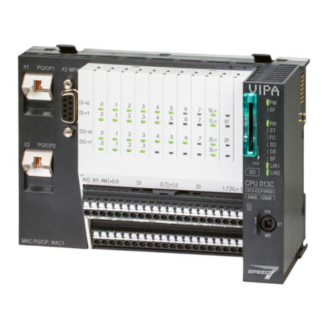
YASKAWA VIPA System SLIO User manual

YASKAWA

YASKAWA VIPA System SLIO User manual

YASKAWA VIPA System SLIO User manual

YASKAWA

YASKAWA VIPA System SLIO User manual

YASKAWA SLIO CP 042-1IO00 User manual

YASKAWA

YASKAWA SLIO CP 042-1IO00 User manual

YASKAWA MECHATROLINK Sigma 2 Series User manual

YASKAWA

YASKAWA MECHATROLINK Sigma 2 Series User manual

YASKAWA CM085 User manual

YASKAWA

YASKAWA CM085 User manual

YASKAWA IM 053MT User manual

YASKAWA

YASKAWA IM 053MT User manual

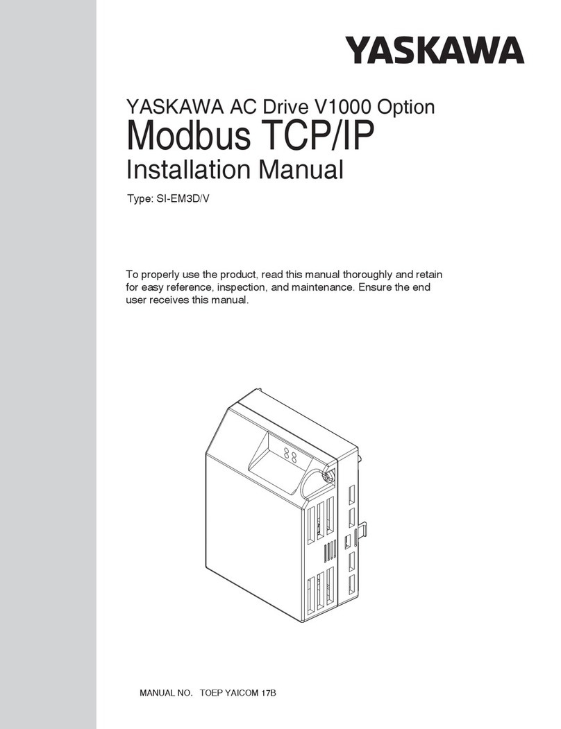
YASKAWA AC Drive V1000 Option SI-EM3/V User manual

YASKAWA

YASKAWA AC Drive V1000 Option SI-EM3/V User manual

YASKAWA GPD 506/P5 User manual

YASKAWA

YASKAWA GPD 506/P5 User manual

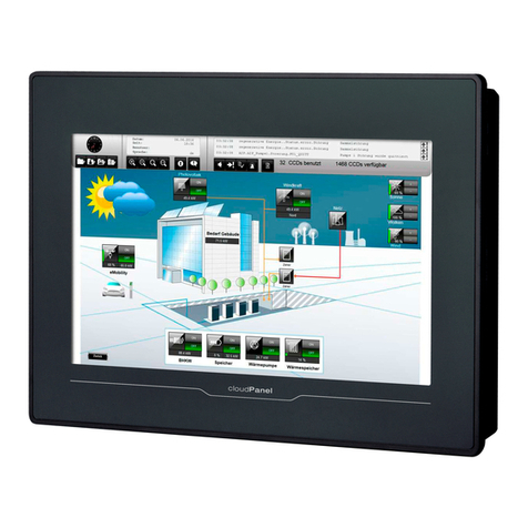
YASKAWA VIPA HMI cloudPanel H41-L1A41-0 User manual

YASKAWA

YASKAWA VIPA HMI cloudPanel H41-L1A41-0 User manual

YASKAWA DO-A3 User manual

YASKAWA

YASKAWA DO-A3 User manual

YASKAWA CANopen SI-S3 User manual

YASKAWA

YASKAWA CANopen SI-S3 User manual

YASKAWA SI-EM3 User manual

YASKAWA

YASKAWA SI-EM3 User manual

YASKAWA U1000 Series User manual

YASKAWA

YASKAWA U1000 Series User manual

YASKAWA S-II Series User manual

YASKAWA

YASKAWA S-II Series User manual

YASKAWA CM092 User manual

YASKAWA

YASKAWA CM092 User manual

YASKAWA V1000 SI-EM3D/V User manual

YASKAWA

YASKAWA V1000 SI-EM3D/V User manual

YASKAWA VIPA System 200V User manual

YASKAWA

YASKAWA VIPA System 200V User manual

Popular Control Unit manuals by other brands

Aqua Medic T controller twin Operation manual

Aqua Medic

Aqua Medic T controller twin Operation manual

Pro-face GP-37W3 Series user manual

Pro-face

Pro-face GP-37W3 Series user manual

Blu Stream ACM500 user manual

Blu Stream

Blu Stream ACM500 user manual

Alfalaval 9611-99-5750 Mounting instructions

Alfalaval

Alfalaval 9611-99-5750 Mounting instructions

Icom UR-FR5100 instructions

Icom

Icom UR-FR5100 instructions

Oriental motor ASTEP AR Series operating manual

Oriental motor

Oriental motor ASTEP AR Series operating manual

Delta MULTICHOICE R22000 manual

Delta

Delta MULTICHOICE R22000 manual

red lion CSTC manual

red lion

red lion CSTC manual

Data Video RMC-180 instruction manual

Data Video

Data Video RMC-180 instruction manual

AutomationDirect D2-DCM user manual

AutomationDirect

AutomationDirect D2-DCM user manual

Tripp Lite Power Accessory Module PAM-3 instruction sheet

Tripp Lite

Tripp Lite Power Accessory Module PAM-3 instruction sheet

IBC control F21075301 manual

IBC control

IBC control F21075301 manual

Lincoln A Series manual

Lincoln

Lincoln A Series manual

DSE 560 operating manual

DSE

DSE 560 operating manual

Metso Neles L4 Series Intallation, Maintenance and Operating Instructions

Metso

Metso Neles L4 Series Intallation, Maintenance and Operating Instructions

Baker Hughes Masoneilan DSH Series instruction manual

Baker Hughes

Baker Hughes Masoneilan DSH Series instruction manual

Intel AXXTPME3 Hardware user's guide

Intel

Intel AXXTPME3 Hardware user's guide

Enerpac MHV-1 manual

Enerpac

Enerpac MHV-1 manual

manuals.online logo
manuals.online logoBrands
  • About & Mission
  • Contact us
  • Privacy Policy
  • Terms and Conditions

Copyright 2025 Manuals.Online. All Rights Reserved.