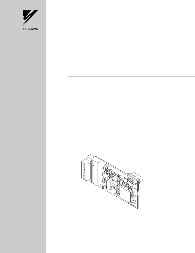
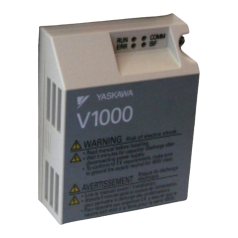
YASKAWA SI-P3V User manual

MANUAL NO. SIEP C730600 23B
Technical Manual
PROFIBUS-DP
Type SI-P3/V
YASKAWA AC Drive-V1000 Option
To properly use the product, read this manual thoroughly and retain
for easy reference, inspection, and maintenance. Ensure the end user
receives this manual.

This Page Intentionally Blank

YASKAWA ELECTRIC SIEP C730600 23B V1000 Option PROFIBUS-DP Technical Manual 3
Table of Contents
1 PREFACE AND SAFETY . . . . . . . . . . . . . . . . . . . . . . . . . . . . . . . . . . . . . . . . . . . . . . . . 4
2 PRODUCT OVERVIEW. . . . . . . . . . . . . . . . . . . . . . . . . . . . . . . . . . . . . . . . . . . . . . . . . . 7
3 RECEIVING . . . . . . . . . . . . . . . . . . . . . . . . . . . . . . . . . . . . . . . . . . . . . . . . . . . . . . . . . . . 8
4 PROFIBUS-DP OPTION COMPONENTS . . . . . . . . . . . . . . . . . . . . . . . . . . . . . . . . . . . 9
5 INSTALLATION PROCEDURE . . . . . . . . . . . . . . . . . . . . . . . . . . . . . . . . . . . . . . . . . . 12
6 PROFIBUS-DP OPTION DRIVE PARAMETERS . . . . . . . . . . . . . . . . . . . . . . . . . . . . . 17
7 CONVENTIONAL FORMATS . . . . . . . . . . . . . . . . . . . . . . . . . . . . . . . . . . . . . . . . . . . . 18
8 PARAMETER PROCESS DATA OBJECT FORMATS . . . . . . . . . . . . . . . . . . . . . . . . 26
9 TROUBLESHOOTING . . . . . . . . . . . . . . . . . . . . . . . . . . . . . . . . . . . . . . . . . . . . . . . . . 37
10 SPECIFICATIONS. . . . . . . . . . . . . . . . . . . . . . . . . . . . . . . . . . . . . . . . . . . . . . . . . . . . 39
Copyright © 2007 YASKAWA ELECTRIC CORPORATION
All rights reserved. No part of this publication may be reproduced, stored in a retrieval system, or transmitted,
in any form or by any means, mechanical, electronic, photocopying, recording, or otherwise, without the prior
written permission of Yaskawa. No patent liability is assumed with respect to the use of the information
contained herein. Moreover, because Yaskawa is constantly striving to improve its high-quality products, the
information contained in this manual is subject to change without notice. Every precaution has been taken in
the preparation of this manual. Yaskawa assumes no responsibility for errors or omissions. Neither is any
liability assumed for damages resulting from the use of the information contained in this publication.

4 YASKAWA ELECTRIC SIEP C730600 23B V1000 Option PROFIBUS-DP Technical Manual
1 Preface and Safety
Yaskawa manufactures products used as components in a wide variety of industrial systems and equipment. The selection
and application of Yaskawa products remain the responsibility of the equipment manufacturer or end user. Yaskawa
accepts no responsibility for the way its products are incorporated into the final system design. Under no circumstances
should any Yaskawa product be incorporated into any product or design as the exclusive or sole safety control. Without
exception, all controls should be designed to detect faults dynamically and fail safely under all circumstances. All
systems or equipment designed to incorporate a product manufactured by Yaskawa must be supplied to the end user with
appropriate warnings and instructions as to the safe use and operation of that part. Any warnings provided by Yaskawa
must be promptly provided to the end user. Yaskawa offers an express warranty only as to the quality of its products in
conforming to standards and specifications published in the Yaskawa manual. NO OTHER WARRANTY, EXPRESS OR
IMPLIED, IS OFFERED. Yaskawa assumes no liability for any personal injury, property damage, losses, or claims
arising from misapplication of its products.
Applicable Documentation
The following manuals are available for the PROFIBUS-DP Option:
Terms
Note: Indicates a supplement or precaution that does not cause drive damage.
Registered Trademarks
• PROFIBUS-DP is a registered trademark of PROFIBUS International.
• Other company names and product names listed in this manual are registered trademarks of those companies.
Option Unit
Yaskawa AC Drive -V1000 Option PROFIBUS-DP Installation Manual
Manual No.: TOBPC73060023
Read this manual first.
The installation manual is packaged with the PROFIBUS-DP Option and contains a basic overview of wiring,
settings, functions, and fault diagnoses.
Yaskawa AC Drive -V1000 Option PROFIBUS-DP Technical Manual
Manual No.: SIEPC73060023
The technical manual contains detailed information and command registers.
To obtain the technical manual access these sites:
U.S.: http://www.yaskawa.com
Europe: http://www.yaskawa.eu.com
Japan: http://www.e-mechatronics.com
Other areas: contact a Yaskawa representative.
Yaskawa Drive
Yaskawa AC Drive-V1000 Technical
Manual
To obtain instruction manuals for Yaskawa products access these sites:
U.S.: http://www.yaskawa.com
Europe: http://www.yaskawa.eu.com
Japan: http://www.e-mechatronics.com
Other areas: contact a Yaskawa representative.
For questions, contact the local Yaskawa sales office or the nearest
Yaskawa representative.
Yaskawa AC Drive-V1000 Quick Start
Guide
Drive: Yaskawa AC Drive -V1000 Series
PROFIBUS Option: Yaskawa AC Drive -V1000 Option PROFIBUS-DP
STOP
(Hz)
(Hz)
(A)
(V)
V1000
ᵄᢙᜰ
ᱜォㅒォㆬᛯ
ജᵄᢙ
ജ㔚ᵹ
ജ㔚
ࡕ࠾࠲
ࡌࡈࠔࠗ
࠶࠻ࠕ࠶ࡊ
ࡄࡔ࠲⸳ቯ
ࠝ࠻࠴ࡘ࠾ࡦࠣ
ᝪ߃ઃߌޔㆇォߩ೨ߦߪᔅߕขᛒ⺑ᦠࠍ⺒ߎߣޕ
ㅢ㔚߅ࠃ߮㔚Ḯㆤᢿᓟ
5
ಽએౝߪࡈࡠࡦ࠻ࠞࡃࠍ
ᄖߐߥߎߣޕ
400V
⚖ࠗࡦࡃ࠲ߩ႐วߪޔ㔚Ḯߩᕈὐ߇ធ
ߐࠇߡࠆߎߣࠍ⏕ߔࠆߎߣޕ㧔ޓޓኻᔕ㧕
ߌ߇㧚ᗵ㔚ߩ߅ߘࠇ߇ࠅ߹ߔޕ
ෂޓ㒾
1 Preface and Safety
YASKAWA ELECTRIC SIEP C730600 23B V1000 Option PROFIBUS-DP Technical Manual 5
Supplemental Safety Information
Read and understand this manual before installing, operating, or servicing this option unit. The option unit must be
installed according to this manual and local codes.
The following conventions are used to indicate safety messages in this manual. Failure to heed these messages could
result in serious or possibly even fatal injury or damage to the products or to related equipment and systems.
General Safety
DANGER
Indicates a hazardous situation, which, if not avoided, will result in death or serious injury.
WARNING
Indicates a hazardous situation, which, if not avoided, could result in death or serious injury.
CAUTION
Indicates a hazardous situation, which, if not avoided, could result in minor or moderate injury.
NOTICE
Indicates an equipment damage message.
General Precautions
• The diagrams in this section may include option units and drives without covers or safety shields to illustrate details. Be sure to reinstall covers
or shields before operating any devices. The option board should be used according to the instructions described in this manual.
• Any illustrations, photographs, or examples used in this manual are provided as examples only and may not apply to all products to which this
manual is applicable.
• The products and specifications described in this manual or the content and presentation of the manual may be changed without notice to
improve the product and/or the manual.
• When ordering a new copy of the manual due to damage or loss, contact your Yaskawa representative or the nearest Yaskawa sales office and
provide the manual number shown on the front cover.
DANGER
Heed the safety messages in this manual.
Failure to comply will result in death or serious injury.
The operating company is responsible for any injuries or equipment damage resulting from failure to heed the warnings
in this manual.
NOTICE
Do not expose the drive to halogen group disinfectants.
Failure to comply may cause damage to the electrical components in the option unit.
Do not pack the drive in wooden materials that have been fumigated or sterilized.
Do not sterilize the entire package after the product is packed.
Do not modify the drive circuitry.
Failure to comply could result in damage to the drive and will void warranty.
YASKAWA is not responsible for any modification of the product made by the user. This product must not be
modified.

1 Preface and Safety
6YASKAWA ELECTRIC SIEP C730600 23B V1000 Option PROFIBUS-DP Technical Manual
Option Unit Label Warnings
Warning information is displayed on the option unit as shown in the figure below. Follow all warnings and safety
instructions when using the product.
When using the drive in an area that may require displaying warning information in Japanese or Chinese, a sticker is
provided with the PROFIBUS-DP Option. This sticker can be placed over the English and French warnings on the front
of the PROFIBUS-DP Option.
Figure 1
Figure 1 Warning Labels
Warning Contents
V1000
Warning
information
AVERTISSEMENT
Lire le manuel avant l'installation.
Attendre 5 minutes apres la coupure de l'alimentation,
pour permettre la decharge des condensateurs.
Pour repondre aux exigences , s assurer que le
neutre soit relie a la terre, pour la serie 400V.
WARNING
Read manual before installing.
Wait 5 minutes for capacitor discharge after
disconnecting power supply.
To conform to ޓrequirements, make sure
to ground the supply neutral for 400V class.
Risk of electric shock.
Risque de decharge
electrique.

2 Product Overview
YASKAWA ELECTRIC SIEP C730600 23B V1000 Option PROFIBUS-DP Technical Manual 7
2 Product Overview
About This Product
PROFIBUS is an open digital communication system supporting a wide range of fast, time-critical applications.
PROFIBUS-DP (Decentral Periphery) is one of the three PROFIBUS variants. DP is dedicated to fast data
communication between systems and peripherals at a field level. This PROFIBUS-DP Option connects a drive to a field
network using the PROFIBUS-DP protocol.
PROFIBUS-DP is included into the European Fieldbus Standard EN 50170.
The network is primarily used in process and factory automation.
By installing the PROFIBUS-DP Option to a drive, it is possible to do the following from a PROFIBUS-DP master
device:
• operate the drive
• monitor the operation status of the drive
• change parameter settings
Applicable Models
The PROFIBUS-DP Option can be used with the drive models in Table 1.
Table 1 Applicable Models
Drive Software Version <1>
CIMR-VAA
<1> See “PRG” on the drive nameplate for the software version number.
≥ 1010

8 YASKAWA ELECTRIC SIEP C730600 23B V1000 Option PROFIBUS-DP Technical Manual
3 Receiving
3 Receiving
Please perform the following tasks after receiving the PROFIBUS-DP Option:
• Inspect the PROFIBUS-DP Option for damage.
If the PROFIBUS-DP Option appears damaged upon receipt, contact the shipper immediately.
• Verify receipt of the correct model by checking the information on the nameplate (see Figure 2).
• If you receive the wrong model or the PROFIBUS-DP Option does not function properly, contact your supplier.
Contents and Packaging
Table 2 Contents of Package
Tool Requirements
Note: Tools required to prepare PROFIBUS cables for wiring are not listed in this manual.
Description: Option Unit Ground Cables Warning Labels Installation Manual
_
Quantity: 1 4 1 1
A Phillips screwdriver (M3, M3.5 to M6 <1>) metric or (#1, #2 <1>) U.S. standard size is required to install the PROFIBUS-DP Option.
<1> Screw sizes vary by drive capacity. Select a screwdriver that matches the drive capacity.
MANUAL

4 PROFIBUS-DP Option Components
YASKAWA ELECTRIC SIEP C730600 23B V1000 Option PROFIBUS-DP Technical Manual 9
4 PROFIBUS-DP Option Components
PROFIBUS-DP Option
Figure 2
Figure 2 Option Unit
Note: For details on the LEDs, Refer to PROFIBUS-DP Option LED Display on page 10.
Dimensions
The installed PROFIBUS-DP Option adds 27 mm (1.06 in.) to the total depth of the drive. (Figure 3)
Figure 3
Figure 3 Dimensions
Communication connector
The drive has a 9 pin D-sub connector for installing the option card. Once installed, the drive can connect to a
PROFIBUS network.
A – LED (Comm: green)
<1> Cables are not connected to the PROFIBUS-DP Option and are packaged separately in
the box.
H–Nameplate
B – LED (BF: red) I – Function Earth cable
connection (FE)
C – Option cover J – Mounting clip
D – LED (ERR: red) K – Cable <1>
E – LED (RUN: green) L – Through-hole for cable
F – PROFIBUS-DP PCB M – Communication cable
connector (9-pin D-SUB)
G – Attachment screw hole for
option cover
N – Option board connector
N
J
G
F
J
I
K
L
PROFIBUS-DP with cover removed
Underside
M
SI-P3
FE
AE
DB
C
PROFIBUS-DP with cover attached
H
RUN
ERR
COMM
BF
27 mm (1.06 in.)

4 PROFIBUS-DP Option Components
10 YASKAWA ELECTRIC SIEP C730600 23B V1000 Option PROFIBUS-DP Technical Manual
Figure 4
Figure 4 Communication connector location
Table 3 Communication connector (9-pin D-SUB)
PROFIBUS-DP Option LED Display
Table 4 LED Display
PROFIBUS Connector Pin Signal Description
1 Shield Connected to the metal-shell (no direct FG-connection)
2– –
3 RxD/TxD-P Receive/Transmit data; line B (red)
4 CNTR-P Control signal for repeaters (direction control)
5 DGND Data ground (reference voltage to VP)
6 VP Power supply output for bus termination (for termination resistor)
7– –
8 RxD/TxD-N Receive/Transmit data; line A (green)
9– –
LED Display Communication
Status Meaning
Color Status
RUN
(Power) Green
ON Power is on Power is being properly supplied to SI-P3/V, and SI-P3/V has completed its
hardware self-diagnostics check
OFF Power is off
• The drive has no power supply
• SI-P3/V and drive are not connected properly and/or there is no power
supplied to the SI-P3/V
• An internal, self-diagnostic error occurred in the SI-P3/V
ERR
(Option Error) Red
ON SI-P3/V error Self-diagnostics error occurred in the SI-P3/V
Flashing Drive connection error Connection error between SI-P3/V and drive. This includes node address
setting errors to parameter F6-30 on the drive side
OFF Normal operation Drive and SI-P3/V are properly connected
COMM
(Communication
Status)
Green
ON Communication
connected Normal send/receive between SI-P3/V and PROFIBUS-DP master
OFF No data exchange There is a problem establishing communication between SI-P3/V and the
PROFIBUS-DP master
BF
(PROFIBUS-DP
Error)
Red
ON
Waiting for
communication
procedure setting
Communication-related parameters are being set or initialized by the
PROFIBUS-DP master.
Flashing Communication setting
error Communication parameter error from PROFIBUS-DP master
OFF Normal operation LED is off once the PROFIBUS-DP master is finished setting
communication-related parameters
1
5
6
9
Bottom View
7
8
2
3
4

4 PROFIBUS-DP Option Components
YASKAWA ELECTRIC SIEP C730600 23B V1000 Option PROFIBUS-DP Technical Manual 11
Table 5 Understanding LED Display
{: On / : Flashing / ×: Off
Setting Node Address
Set drive parameter F6-30 to a unique node address (Range 0 to 125) on the network.
LED Communication Status Possible Cause Solution
RUN ERR COMM BF
×× ××No power
The drive has no power Check all wiring to the drive, then turn the power
on
SI-P3/V is not properly connected
to the drive, and therefore is not
receiving enough power
• Shut the drive off and check that the PROFIBUS
DP Option is properly connected
• Turn the power back on again
{×××
• Checking connection
with the drive
• Waiting for data from
the master
• SI-P3/V is reading the node
address or parameter
configuration
• Waiting for initial input data
from master device
–
×{××
SI-P3/V Self-diagnostics
error
The PROFIBUS-DP Option is
damaged
Cycle power to the drive. If the LED status does
not change, replace the PROFIBUS-DP Option
×××
Problem connecting to the
drive
• Problem initializing the drive
and SI-P3/V
• Incorrect node address
• Cycle power to the drive. If the LED status does
not change, replace the PROFIBUS-DP Option
• Check the node address setting in the drive
(parameter F6-10)
{××{Waiting for data from the
master device
Waiting for data from the master
device (Set_Parm_Message or
Chk_Cfg_Message)
• Check the network settings in the master
• Make sure the master device is operating
normally
• Check the terminal resistance settings on the data
line
• Look for any problems with the data line, or if
the connector
• Check that the data lines are properly connected
to the drive
{××
Data is incorrect or
PROFIBUS-DP Option
timed out waiting for data
The communication procedure in
the master is set incorrectly
• Check the communication procedure settings in
the master
{×{×Sending or receiving data – –

12 YASKAWA ELECTRIC SIEP C730600 23B V1000 Option PROFIBUS-DP Technical Manual
5 Installation Procedure
Section Safety
DANGER
Electrical Shock Hazard
Do not connect or disconnect wiring while the power is on.
Failure to comply will result in death or serious injury.
Disconnect all power to the drive, wait at least five minutes after all indicators are off, measure the DC bus
voltage to confirm safe level, and check for unsafe voltages before servicing to prevent electric shock. The
internal capacitor remains charged even after the power supply is turned off. The charge indicator LED will
extinguish when the DC bus voltage is below 50 Vdc.
WARNING
Electrical Shock Hazard
Do not remove option board cover while the power is on.
Failure to comply could result in death or serious injury.
The diagrams in this section may include option units and drives without covers or safety shields to show
details. Be sure to reinstall covers or shields before operating any devices. The option board should be used
according to the instructions described in this manual.
Do not allow unqualified personnel to use equipment.
Failure to comply could result in death or serious injury.
Maintenance, inspection, and replacement of parts must be performed only by authorized personnel familiar
with installation, adjustment, and maintenance of this product.
Do not use damaged wires, place excessive stress on wiring, or damage the wire insulation.
Failure to comply could result in death or serious injury.
NOTICE
Damage to Equipment
Observe proper electrostatic discharge procedures (ESD) when handling the option unit, drive, and
circuit boards.
Failure to comply may result in ESD damage to circuitry.
Never shut the power off while the drive is outputting voltage.
Failure to comply may cause the application to operate incorrectly or damage the drive.
Do not operate damaged equipment.
Failure to comply may cause further damage to the equipment.
Do not connect or operate any equipment with visible damage or missing parts.
Do not use unshielded cable for control wiring.
Failure to comply may cause electrical interference resulting in poor system performance.
Use shielded twisted-pair wires and ground the shield to the ground terminal of the drive.

5 Installation Procedure
YASKAWA ELECTRIC SIEP C730600 23B V1000 Option PROFIBUS-DP Technical Manual 13
Connection Diagram
Figure 5 Connection Diagram
PROFIBUS-DP Termination
Because the option card does not have a termination resistor, a termination resistance must be set using a switch on the 9
pin D-sub connector. Make sure that only the D-sub connector for the last or end drive in the network has a terminating
resistor. If any other drive on the network has a terminating resistor, communication problems may occur.
Most 9 pin D-sub connectors have a function for disconnecting the output side of the cable. Use only the input side cable
entry when connecting both ends of the network. If the connector is reversed, then communication will not be possible
between devices. Most connectors have arrows indicating the input and output sides.
Terminating resistors are shown in Figure 6 can only be used. for baud rates below 1.5 Mbps. 1.5 Mbps and higher baud
rates require termination with resistors as shown in Figure 7
Figure 5
Figure 6 PROFIBUS Cable Connection with Termination Resistors
Properly connect all pins and connectors.
Failure to comply may prevent proper operation and possibly damage equipment.
Check wiring to ensure that all connections are correct after installing the option unit and connecting
any other devices.
Failure to comply may result in damage to the option unit.
<1> The FE terminal on the PROFIBUS-DP Option is fitted with a ground cable that should be connected to the ground terminal on the drive.
Bus termination ON = incoming and outgoing cables not connected.
Bus termination OFF = incoming and outgoing cables connected.
NOTICE
V1000
9-pin D-SUB Connector
For the last node on the bus,
turn on the termination resistor switch.
SI-P3/V
RTS
DGND
VP
A-line
B-line
390Ω220Ω390Ω
1B
1A
3
8
4
6
5
2B
2A
CN5
FE
<1>
PROFIBUS Cable PROFIBUS Cable Connector
(Red)
(Green)
(Red)
(Green)
(Shell)
To PROFIBUS-DP
Master
To the next slave
(Shell)
ON
OFF
Outgoing Cable
Incoming Cable
Switch
Bus termination
9-pin D-sub Connector
OO
O

5 Installation Procedure
14 YASKAWA ELECTRIC SIEP C730600 23B V1000 Option PROFIBUS-DP Technical Manual
Figure 6
Figure 7 Cable Termination of the PROFIBUS-DP Option Cable to EN50170
(pin numbers for a 9-pin D-sub connector)
Prior to Installing the Option Unit
Prior to installing the PROFIBUS-DP Option, wire the drive and make necessary connections to the drive terminals.
Refer to the YASKAWA AC Drive Quick Start Guide for information on wiring and connecting the drive. Verify that the
drive operates normally without the option installed.
Installing the Option Unit
Remove the front cover of the drive before installing the PROFIBUS-DP Option. Follow the directions below for proper
installation.
1. Switch off the power supply to the drive.
DANGER! Electrical Shock Hazard - Do not connect or disconnect wiring while the power is on. Failure to comply will result in death
or serious injury. Before installing the PROFIBUS-DP Option, disconnect all power to the drive. The internal capacitor remains charged
even after the power supply is turned off. The charge indicator LED will extinguish when the DC bus voltage is below 50 Vdc. To
prevent electric shock, wait at least five minutes after all indicators are off and measure the DC bus voltage level to confirm safe level.
2. Remove the front cover. The original drive front cover may be discarded because it will be replaced by the
PROFIBUS-DP Option cover in step 7.
Figure 7
Figure 8 Remove Front Cover
3. Remove the bottom cover and connect the PROFIBUS-DP Option ground cable to the ground terminal.
Figure 8
Figure 9 Connect Ground Cable
Note: The four different ground cables packaged with the PROFIBUS-DP Option connect to different models. Select the proper ground
cable from the PROFIBUS-DP Option kit depending on drive size.
390 Ω
B - Data line
DGND (pin 5)
RxD/TxD-N (pin 8)
RxD/TxD-P (pin 3)
VP (pin 6)
A - Data line
220 Ω
390 Ω
Ground terminal
Ground cable
Bottom cover

5 Installation Procedure
YASKAWA ELECTRIC SIEP C730600 23B V1000 Option PROFIBUS-DP Technical Manual 15
Figure 9
Figure 10 Ground Cable
Note: Cover removal for certain larger models with a Terminal Cover:
-Single-Phase 200 V Class: CIMR-VBA0006 to BA0018
-Three-Phase 200 V Class: CIMR-V2A0008 to 2A0069
-Three-Phase 400 V Class: All models
Remove the terminal cover before removing the bottom cover to install the PROFIBUS-DP Option. Replace the terminal cover
after wiring the PROFIBUS-DP Option.
Figure 10
Figure 11 Models with Terminal Cover
4. Reattach the bottom cover.
5. Connect the PROFIBUS-DP Option to the drive. Properly secure the tabs on the left and right sides of the PROFIBUS-
DP Option to the drive case.
Figure 11
Figure 12 Attach PROFIBUS-DP Option
6. Connect the ground cable from the drive ground terminal to the PROFIBUS-DP Option ground. When wiring the
PROFIBUS-DP Option, pass the ground cable through the inside of the drive bottom cover, then pass the ground cable
into the through-hole at the front of the PROFIBUS-DP Option.
Figure 12
Figure 13 Ground Cable Connection
A – Option unit connection: screw size = M3
B – Drive-side connection: screw size = M3.5 to M6
AB
Tabs should line up
Tabs should line up
Ground
cable
Drive ground
terminal
Pass the ground
cable through
the bottom cover
of the drive.
Through-hole
for ground cable
Ground cable

5 Installation Procedure
16 YASKAWA ELECTRIC SIEP C730600 23B V1000 Option PROFIBUS-DP Technical Manual
7. Attach the PROFIBUS-DP Option cover to the front of the PROFIBUS-DP Option.
Figure 13
Figure 14 Attach Cover
Note: When using the drive in an area that may require displaying warning information in Japanese or Chinese, a label is provided with
the Profibus-DP Option. This label can be placed over the English and French warnings on the front of the Profibus-DP Option.
Communication Cable Specifications
To ensure proper performance, Yaskawa recommends using PROFIBUS-DP-dedicated cables that fulfill the
specifications in Table 6. For more information on cables, refer to the PROFIBUS-DP website at http://
www.profibus.com.
Cable Requirements
Table 6 Communication Cable Requirements
Cable Length
Communication speed determines maximum permissible cable length. Table 7 shows the specifications for Type A bus
cables.
Table 7 Cable Length
GSD Files
For easy network implementation of drives equipped with an SI-P3/V, a GSD file can be obtained from:
U.S.: http://www.yaskawa.com
Europe: http://www.yaskawa.eu.com
Japan: http://www.e-mechatronics.com
Other areas: Contact a Yaskawa representative.
Condition Specifications
Impedance 135 to 165 Ω at a frequency of (3 to 20 MHz)
Capacity 30 pF/m maximum
Loop Resistance 110 Ω/km maximum
Core Cross-Section 0.34 mm2minimum
Core Diameter 0.64 mm minimum
Communication speed
(kbps) Distance per segment (m) Communication speed (kbps) Distance per segment (m)
9.6 1200 500 400
19.2 1200 1500 200
45.45 1200 3000 100
93.75 1200 6000 100
187.5 1000 12000 100
Tabs should line up

6 PROFIBUS-DP Option Drive Parameters
YASKAWA ELECTRIC SIEP C730600 23B V1000 Option PROFIBUS-DP Technical Manual 17
6 PROFIBUS-DP Option Drive Parameters
Confirm the proper setting of all parameters in Table 8 before starting network parameters.
Table 8 Parameter Settings
No. Name Description Default
b1-01
<1>
<1> To start and stop the drive through the PROFIBUS-DP network, set b1-02 to “3”. To control the frequency reference of the drive via the
PROFIBUS-DP network, set b1-01 to “3”.
<2> If F6-03 is set to 3, then the drive will continue to operate when an EF0 fault is detected. Take proper safety measures, such as installing an
emergency stop switch.
<3> Software versions 1012 and later have F6-07 and F6-08 both set to 1.
<4> All node addresses must be unique. Node addresses 0, 1, and 2 are typically reserved for control, maintenance, and diagnostic equipment. The
ERR light will illuminate when 0 or greater than 125 is entered.
<5> Power must be cycled in order for any setting changes to take affect.
<6> CIMR-VC drives do not have the terminal S7 (Multi-function digital input command 7).
Frequency Reference Selection
Selects the frequency reference input source
0: Operator - Digital preset speed d1-01 to d1-17
1: Terminals - Analog input terminal A1 or A2
2: MEMOBUS/Modbus communications
3: Option PCB
4: Pulse Input (Terminal RP)
1
b1-02
<1> Run Command Selection
Selects the run command input source
0: Digital Operator - RUN and STOP keys
1: Digital input terminals S1 to S7 <6>
2: MEMOBUS/Modbus communications
3: Option PCB
1
F6-01 Operation Selection after
Communications Error
Determines drive response when a bUS error is detected during
communications with the PROFIBUS-DP Option
0: Ramp to Stop
1: Coast to Stop
2: Fast-Stop
3: Alarm Only <2>
1
F6-02 External Fault Detection Conditions (EF0)
Sets the condition for external fault detection (EF0)
0: Always detected
1: Detected only during operation
0
F6-03 Stopping Method for External Fault from
Communication Option Board
Determines drive response for external fault input (EF0) detection
during PROFIBUS communication
0: Ramp to Stop
1: Coast to Stop
2: Fast-Stop
3: Alarm Only <2>
1
F6-07
<3> NetRef/ComRef Selection Function 0: Multi-step speed reference disabled (F7 mode)
1: Multi-step speed reference allowed (V7 mode) 1
F6-08
<3> Reset Communication Related Parameters
Determines which communication-related parameters are set back to
their original default values when the drive is initialized
0: Do not reset F6- and F7- parameters when the drive is
initialized using parameter A1-03
1: Rest F6- and F7- parameters when the drive is initialized
using parameter A1-03
Setting this parameter does not affect communication-related parameters
0
F6-30
<4> <5> Node Address 0 to 125 0
F6-31 Clear Mode Selection
Selects the action to take when a "Clear Mode" command is received
0: Resets back to 0
1: Maintains the previous value
0
F6-32
<5> PROFIBUS Map Selection 0: PPO Type
1: Conventional 0

18 YASKAWA ELECTRIC SIEP C730600 23B V1000 Option PROFIBUS-DP Technical Manual
7 Conventional Formats
Conventional Formats
The configuration tool of PROFIBUS-DP master sets the input and output data length of SI-P3/V from Extended Data 1
(32 bytes), Extended Data 2 (12 bytes), and Basic Data (6 bytes).
Conventional formats have two message types: High-speed I/O Data and MEMOBUS/Modbus message.
Set parameter F6-32 to “1” to use conventional formats.
High-Speed I/O Data
High-speed I/O data is directly transferred to or from the drive and can control the drive. For example, when the drive is
set for PROFIBUS-DP communications, the drive Run/Stop and Frequency Reference commands are typically
transferred to the drive within 2 ms after being received by the option.
MEMOBUS/Modbus Message
MEMOBUS/Modbus message data is transferred to the drive using MEMOBUS/Modbus messages. All drive parameters
and data can be accessed through MEMOBUS/Modbus. Because the data in this message type is transferred to the drive
after the SI-P3/V receives and edits it, more time is required to return the data to the master. The master must synchronize
the timing of sending and receiving the data by handshaking.
Memory Maps
The following memory maps show the I/O data bytes.
Basic and Extended Register Maps
Table 9 Basic Data Register Map Detail
Table 10 Extended Data 1 Register Map
Basic Data
(6 bytes)
Extended Data 1
(32 bytes)
Extended Data 2
(12 bytes)
High-speed I/O Data Bytes 0 to 5 Bytes 0 to 15 Bytes 0 to 3
MEMOBUS/Modbus Data – Bytes 16 to 31 Bytes 4 to 11
Output (Master Device to Drive) Input (Drive to Master Device)
Byte
<1> Unit depends on the setting of o1-03 (Digital Operator Display Scaling). When the drive is operating in the V/f Control mode, the drive's output
frequency becomes the input data.
<2> Data is displayed in units of either 0.01 A for drives 7.5 kW and smaller, or in units of 0.1 A for drives 11 kW and larger. This is the same
regardless of whether the drive is set for Normal Duty or Heavy Duty operation.
Description Byte Description
0 Operation Command (High Byte) 0 Drive Status (High Byte)
1 Operation Command (Low Byte) 1 Drive Status (Low Byte)
2 Frequency Reference (High Byte) 2 Motor Speed (High Byte) <1>
3 Frequency Reference (Low Byte) 3 Motor Speed (Low Byte) <1>
4Reserved 4 Output Current (High Byte) <2>
5 5 Output Current (Low Byte) <2>
Output (Master Device to Drive) Input (Drive to Master Device)
Byte Description Byte Description
0 Operation Command (High Byte) 0 Drive Status (High Byte)
1 Operation Command (Low Byte) 1 Drive Status (Low Byte)
2 Frequency Reference (High Byte) 2 Motor Speed (High Byte) <3>
3 Frequency Reference (Low Byte) 3 Motor Speed (Low Byte) <3>

7 Conventional Formats
YASKAWA ELECTRIC SIEP C730600 23B V1000 Option PROFIBUS-DP Technical Manual 19
Table 11 Operation Command
4
Reserved
4 Torque Reference Monitor (High Byte) <4>
5 5 Torque Reference Monitor (Low Byte) <4>
66
Reserved
77
8 8 Frequency Reference (High Byte)
9 9 Frequency Reference (Low Byte)
10 Analog Output Channel 1 (High Byte) <1> 10 Output Frequency (High Byte)
11 Analog Output Channel 1 (Low Byte) <1> 11 Output Frequency (Low Byte)
12 Reserved 12 Output Current (High Byte) <5>
13 13 Output Current (Low Byte) <5>
14 Digital Output (High Byte) <2> 14 Analog Input Channel 1 (High Byte)
15 Digital Output (Low Byte) <2> 15 Analog Input Channel 1 (Low Byte)
16 MEMOBUS/Modbus Function Code 16 MEMOBUS/Modbus Function Code
17 MEMOBUS/Modbus Starting Register Address
(High Byte) 17 MEMOBUS/Modbus Starting Register Address
(High Byte)
18 MEMOBUS/Modbus Starting Register Address
(Low Byte) 18 MEMOBUS/Modbus Starting Register Address
(Low Byte)
19 MEMOBUS/Modbus Number of Data 19 MEMOBUS/Modbus Number of Data
20 MEMOBUS/Modbus Data 1 (High Byte) 20 MEMOBUS/Modbus Data 1 (High Byte)
21 MEMOBUS/Modbus Data 1 (Low Byte) 21 MEMOBUS/Modbus Data 1 (Low Byte)
22 MEMOBUS/Modbus Data 2 (High Byte) 22 MEMOBUS/Modbus Data 2 (High Byte)
23 MEMOBUS/Modbus Data 2 (Low Byte) 23 MEMOBUS/Modbus Data 2 (Low Byte)
24 MEMOBUS/Modbus Data 3 (High Byte) 24 MEMOBUS/Modbus Data 3 (High Byte)
25 MEMOBUS/Modbus Data 3 (Low Byte) 25 MEMOBUS/Modbus Data 3 (Low Byte)
26 MEMOBUS/Modbus Data 4 (High Byte) 26 MEMOBUS/Modbus Data 4 (High Byte)
27 MEMOBUS/Modbus Data 4 (Low Byte) 27 MEMOBUS/Modbus Data 4 (Low Byte)
28
Reserved
28
Reserved29 29
30 30
31 Handshaking Register 31 Handshaking Register
<1> To select drive analog output channel for communications, set H4-01 (Multi-Function Analog Output Terminal AM) to 000 (through-mode).
<2> Drive digital output ON/OFF during communications, set H2-01 (Terminal MA, MB and MC Function Selection (relay)), H2-02 (Terminal P1
Function Selection (open-collector)), and H2-03 (Terminal P2 Function Selection (open-collector)) to F (through-mode).
<3> Unit depends on the setting of o1-03 (Digital Operator Display Scaling). Input data is 0 when the drive is set for V/f Control.
<4> Cannot be used when setting A1-02 (Control Method Selection) to 0 (V/f Control without PG).
<5> Data is displayed in units of either 0.01 A for drives 7.5 kW and smaller, or in units of 0.1 A for drives 11 kW and larger. This is the same
regardless of whether the drive is set for Normal Duty or Heavy Duty operation.
Command Signal Description
0H5-12 = 0: Forward Run/Stop, 1: FRUN
H5-12 = 1: Run/Stop, 1: RUN
1H5-12 = 0: Reverse Run/Stop, 1: RRUN
H5-12 = 1: Forward/Reverse, 1: REV
2 Multi-function digital input command 3
3 Multi-function digital input command 4
4 Multi-function digital input command 5
5 Multi-function digital input command 6
6 Multi-function digital input command 7 <1>
7 Reserved
8 External Fault, 1: Fault (EF0)
9 Fault Reset, 1: Fault Reset
A
Reserved
B
C
D
Output (Master Device to Drive) Input (Drive to Master Device)
Byte Description Byte Description

7 Conventional Formats
20 YASKAWA ELECTRIC SIEP C730600 23B V1000 Option PROFIBUS-DP Technical Manual
Table 12 Drive Status: U1-12
Table 13 Extended Data 2 Register Map
MEMOBUS/Modbus Message Area
In this area, a MEMOBUS/Modbus message is transferred to the SI-P3/V unit, and the parameters in the drive can be set,
read, and monitored. Up to four data items can be written or read at one time.
Because the SI-P3/V unit edits the MEMOBUS/Modbus message internally and transfers it to the drive after receiving
the message, more time is required to return the message. Use the handshaking register to synchronize sending or
receiving of the data between the PROFIBUS-DP master and the SI-P3/V unit. For details on the handshaking register,
refer to Handshaking Register on page 23.
• Execute an Enter command to write a parameter to the drive. Execution of the Enter command validates the written
data. For the details of the Enter command. Refer to the Enter Command in Appendix C of the V1000 Technical
Manual.
EFault Trace and Fault History Reset
1: Fault information is reset by raising edge of this bit
FBaseblock command
1: External Baseblock
<1> CIMR-VC drives do not have Multi-function digital input command 7.
Drive Status Description
0 1: During run
1 1: During zero speed
2 1: During reverse run
3 1: During fault reset signal input
4 1: During speed agree
5 1: Drive ready
61:Alarm
7 1: Fault
8 1: During operation error (oPE)
9 1: During momentary power loss
A 1: NetCtrl status
B 1: MA-MB relay closed
C 1: Photocoupler output 1 closed
D 1: Photocoupler output 2 closed
E 1: Motor 2 selected
F Reserved
Output (Master Device – Drive) Input (Drive – Master Device)
Byte
<1> Unit depends on the setting of o1-03 (Digital Operator Display Scaling). When the drive is operating in the V/f Control mode, the drive's
output frequency becomes the input data.
Description Byte Description
0 Operation Command (High Byte) 0 Drive Status (High Byte)
1 Operation Command (Low Byte) 1 Drive Status (Low Byte)
2 Frequency Reference (High Byte) 2 Motor Speed (High Byte) <1>
3 Frequency Reference (Low Byte) 3 Motor Speed (Low Byte) <1>
4 MEMOBUS/Modbus Function Code 4 MEMOBUS/Modbus Function Code
5 MEMOBUS/Modbus Starting Register Address (High Byte) 5 MEMOBUS/Modbus Starting Register Address (High Byte)
6 MEMOBUS/Modbus Starting Register Address (Low Byte) 6 MEMOBUS/Modbus Starting Register Address (Low Byte)
7 MEMOBUS/Modbus Data Length 7 MEMOBUS/Modbus Data Length
8 MEMOBUS/Modbus Data 1 (High Byte) 8 MEMOBUS/Modbus Data 1 (High Byte)
9 MEMOBUS/Modbus Data 1 (Low Byte) 9 MEMOBUS/Modbus Data 1 (Low Byte)
10 Reserved 10 Reserved
11 Handshaking Register 11 Handshaking Register
Command Signal Description
Other manuals for SI-P3V
2
Table of contents
Other YASKAWA Recording Equipment manuals

YASKAWA
YASKAWA J1000 CIMR-JC series User manual

YASKAWA
YASKAWA VS mini V7 User manual

YASKAWA
YASKAWA SI-T/ V7 User manual

YASKAWA
YASKAWA DeviceNet SI-N3 User manual

YASKAWA
YASKAWA 46S03153-0010 User manual

YASKAWA
YASKAWA SI-232/J User manual

YASKAWA
YASKAWA A1000 Series User manual

YASKAWA
YASKAWA Varispeed f7 User manual

YASKAWA
YASKAWA MECHATROLINK-II V1000 User manual

YASKAWA
YASKAWA CANopen SI-S3 User manual