YASKAWA Varispeed f7 User manual

YASKAWA
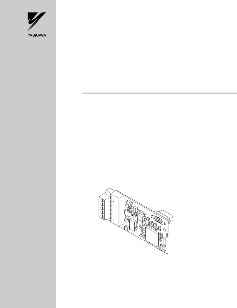
Varispeed G7/F7 OPTION CARD
MECHATROLINK COMMUNICATIONS INTERFACE CARD
USER'S MANUAL
YA S K AWA
MANUAL NO. SIBP C730600 08A
Model: SI-T

Copyright ©2004 YASKAWA ELECTRIC CORPORATION
All rights reserved. No part of this publication may be reproduced, stored in a retrieval system,
or transmitted, in any form, or by any means, mechanical, electronic, photocopying, recording,
or otherwise, without the prior written permission of Yaskawa. No patent liability is assumed
with respect to the use of the information contained herein. Moreover, because Yaskawa is con-
stantly striving to improve its high-quality products, the information contained in this manual is
subject to change without notice. Every precaution has been taken in the preparation of this
manual. Nevertheless, Yaskawa assumes no responsibility for errors or omissions. Neither is
any liability assumed for damages resulting from the use of the information contained in this
publication.

3
Introduction
Thank you for purchasing a Current Vector Control General-purpose Varispeed G7/F7
Inverter and a SI-T MECHATROLINK-I/MECHATROLINK-II Communications Interface
Card (called “SI-T Card” below).
This manual describes the operation and specifications of the SI-T Card, which connects to
the MECHATROLINK-I/MECHATROLINK-II high-speed field network for exchanging
data. Be sure that you have read and understood this manual before attempting to operate the
SI-T Card.
For details on operating the Inverter itself, refer to the Varispeed G7/F7 Series Instruction
Manual (TOE-S616-60.1, TOE-S616-55.1).
Yaskawa Electric, Inc.
General Precautions
• The diagrams in this manual may be indicated without covers or safety shields in order to show
details. Be sure to restore covers or shields before operating the Inverter, and operate the Inverter
according to the instructions provided in this manual.
• The products and specifications described in this manual or the contents and presentation of the
manual may be changed without notice to improve the product and/or the manual.
• When ordering a new copy of the manual due to damage or loss, contact your Yaskawa represen-
tative or the nearest Yaskawa sales office and provide the manual number shown on the front
cover.
• Any modifications to the product by the customer invalidate the warranty, and Yaskawa accepts no
responsibility for the results of any modifications

4
Safety Precautions
Carefully read this manual and all other documentation provided with the product before
attempting to install, operate, inspect, or perform maintenance on the product. Within this
manual, safety-related precautions are classified a “warnings” and “cautions.”
Indicates precautions that, if not heeded, could possibly result in loss of life or seri-
ous injury.
Indicates precautions that, if not heeded, could result in relatively less serious or
minor injury, or damage to the equipment.
Failure to heed even a precaution classified as a caution can result in serious consequences
depending on the situation. All precautions contain important information, so make sure that
they are followed carefully.
Indicates important information that the user should make careful note of, even though it is
not classified as a caution.
WARNING
CAUTION
IMPORTANT

5
Confirmations upon Delivery
Installation and Wiring
Settings
• Never use an Option Card that is damaged or missing components.
Doing so can result in injury.
• Never touch the inside of the Inverter with your hands.
Doing so can result in electric shock.
• Before installing or removing the Option Card, or performing wiring operations, always turn OFF the
power to the Inverter and wait until the specified period of time has elapsed after all the Inverter
indicators have turned OFF. (The time is shown on the Inverter’s front cover.)
Failure to do so can result in electric shock.
• Do not allow cables to be damaged, subjected to stress, placed under heavy objects, or pinched.
Doing so can result in electric shock, faulty operation, or damage to the equipment.
CAUTION
WARNING
• Never touch the Option Card terminals directly with your hands.
Doing so can result in damage from static electricity.
• Insert the connectors securely.
Failure to do so can result in damage or faulty operation of devices.
• Do not carelessly change the Inverter’s settings.
Doing so can result in damage or faulty operation of devices.
CAUTION
CAUTION

6
Warranty Information
Free Warranty Period and Scope
Warranty Period
This product is warranted for twelve months after being delivered to Yaskawa's customer or
if applicable eighteen months from the date of shipment from Yaskawa's factory, whichever
comes first.
Scope of Warranty
Inspections
Periodic inspections must be conducted by the customer. However, upon request, Yaskawa
or one of Yaskawa's Service Centers can inspect the product for a fee. In this case, if after
conferring with the customer, a Yaskawa product is found to be defective due to Yaskawa
workmanship or materials and the defect occurs during the warranty period, then this fee
will be waived and the problem remedied free of charge.
Repairs
If a Yaskawa product is found to be defective due to Yaskawa workmanship or materials and
the defect occurs during the warranty period, Yaskawa will provide a replacement, repair the
defective product, and provide shipping to and from the site free of charge.
However, if the Yaskawa Authorized Service Center determines that the problem with a
Yaskawa product is not due to defects in Yaskawa's workmanship or materials, then the cus-
tomer will be responsible for the cost of any necessary repairs. Some problems that are out-
side the scope of this warranty are:
• Problems due to improper maintenance or handling, carelessness, or other reasons where
the customer is determined to be responsible.
• Problems due to additions or modifications made to a Yaskawa product without
Yaskawa's understanding.
• Problems due to the use of a Yaskawa product under conditions that do not meet the rec-
ommended specifications.
• Problems caused by natural disaster or fire.
• Or other problems not due to defects in Yaskawa workmanship or materials.
Warranty service is only applicable within Japan.
However, after-sales service is available for customers outside of Japan for a reasonable fee.
Contact your local Yaskawa representative for more information.
Exceptions
Any inconvenience to the customer or damage to non-Yaskawa products due to Yaskawa's
defective products whether within or outside the warranty period are NOT covered by this
warranty.
7
Restrictions
• The SI-T Card was not designed or manufactured for use in devices or systems that may
directly affect or threaten human lives or health.
• Customers who intend to use the product described in this manual for devices or systems
relating to transportation, health care, space aviation, atomic or electric power, or under-
water use must contact their Yaskawa representatives or the nearest Yaskawa sales office
beforehand.
• This product has been manufactured under strict quality-control guidelines. However, if
this product is to be installed in any location where failure of this product could involve
or result in a life-and-death situation or loss of human life or in a facility where failure
may cause a serious accident or physical injury, safety devices must be installed to mini-
mize the likelihood of any accident.

8
CONTENTS
Introduction - - - - - - - - - - - - - - - - - - - - - - - - - - - - - - - - - - - - - - - - - - 3
Safety Precautions - - - - - - - - - - - - - - - - - - - - - - - - - - - - - - - - - - - - - 4
Warranty Information - - - - - - - - - - - - - - - - - - - - - - - - - - - - - - - - - - - - 6
Restrictions - - - - - - - - - - - - - - - - - - - - - - - - - - - - - - - - - - - - - - - - - - 7
1 Overview - - - - - - - - - - - - - - - - - - - - - - - - - - - - - - - - - - - - - 10
2 Checking the Product - - - - - - - - - - - - - - - - - - - - - - - - - - - - 10
2.1 Type and Code No. - - - - - - - - - - - - - - - - - - - - - - - - - - - - - - 10
2.2 Parts List - - - - - - - - - - - - - - - - - - - - - - - - - - - - - - - - - - - - - 11
3 Component Names and Settings - - - - - - - - - - - - - - - - - - - - 11
3.1 Component Names - - - - - - - - - - - - - - - - - - - - - - - - - - - - - - 11
3.2 Communications Connectors - - - - - - - - - - - - - - - - - - - - - - - 12
3.3 LED Indicators - - - - - - - - - - - - - - - - - - - - - - - - - - - - - - - - -12
3.4 Switch Setting - - - - - - - - - - - - - - - - - - - - - - - - - - - - - - - - - - 13
4 Installation and Wiring - - - - - - - - - - - - - - - - - - - - - - - - - - - 15
4.1 Installing the SI-T Card - - - - - - - - - - - - - - - - - - - - - - - - - - -15
4.2 MECHATROLINK Communications Cables - - - - - - - - - - - - - 17
5 Transmission Interface - - - - - - - - - - - - - - - - - - - - - - - - - - - 18
5.1 MECHATROLINK-II Cyclic Transmissions - - - - - - - - - - - - - - 18
5.2 Basic Format of Data Transfer - - - - - - - - - - - - - - - - - - - - - - 19
5.3 Communications Phases - - - - - - - - - - - - - - - - - - - - - - - - - - 20
5.4 Application Layer Specifications - - - - - - - - - - - - - - - - - - - - - 21
6 Initial Setup - - - - - - - - - - - - - - - - - - - - - - - - - - - - - - - - - - - 22
7 MECHATROLINK-II Commands - - - - - - - - - - - - - - - - - - - - 23
7.1 Main Commands - - - - - - - - - - - - - - - - - - - - - - - - - - - - - - - - 23
7.2 Sub-commands - - - - - - - - - - - - - - - - - - - - - - - - - - - - - - - - -37
7.3 Status Details - - - - - - - - - - - - - - - - - - - - - - - - - - - - - - - - - - 42
8 Protective Operations - - - - - - - - - - - - - - - - - - - - - - - - - - - - 44
8.1 Fault Detection Processing - - - - - - - - - - - - - - - - - - - - - - - - - 44
8.2 Alarm Processing - - - - - - - - - - - - - - - - - - - - - - - - - - - - - - - 45

9
9 Specifications - - - - - - - - - - - - - - - - - - - - - - - - - - - - - - - - - - 50
Revision History

10
1 Overview
The SI-T Card is an interface card that connects to the MECHATROLINK-I or
MECHATROLINK-II high-speed field network for communicating with the host controller.
By installing the SI-T Card to a Varispeed G7/F7-series Inverter, various applications are
enabled; monitoring of the run/stop status and the operating conditions as well as the changing
and the referencing of the settings for the Inverter constants from the host controller.
The SI-T Card can be installed in the following Inverters.
• Varispeed G7-series Inverter, software No. 656X.
• Varispeed F7-series Inverter (SPEC:E or later), software No.103X.
Note: “X” indicates the design revision order.
Varispeed G7/F7 Inverter with an SI-T Card does not conform to CE Marking, although the Varispeed
G7/F7 Inverter itself conforms to CE Marking.
2 Checking the Product
Check the following items as soon as the product is delivered.
Contact your Yaskawa representative immediately if any failure should be found concerning the
above items.
2.1 Type and Code No.
The following shows the type and code No. on the center of the SI-T Card.
Type: SI-T
Code No.: ETC61862X-S016X
Note: “X” indicates the design revision order.
IMPORTANT
Item Method
Is there any discrepancy between the shipment and
what was ordered?
Check the type and code No. printed on the center of the
Card. (Refer to 2.1 and 3.1.)
Has the product been damaged in any way? Inspect the entire exterior of the Card for any damage that
may have occurred during shipping.
Are the contents of the package correct? Check the contents shown in the following table. (Refer to
2.2.)

3 Component Names and Settings
11
2.2 Parts List
The SI-T Card contains the following parts.
3 Component Names and Settings
3.1 Component Names
The following diagram shows the SI-T Card external appearance and component names.
Parts Name Qty
SI-T Communications Interface Card 1
Grounding cable (Already mounted on the SI-T Card) 1
Instruction Manual (This manual) 1
Code No.
Type
Communications
connectors
Rotary switch
DIP switch
LED

12
3.2 Communications Connectors
The communications connectors (CN1-1 and CN1-2) connect the SI-T Card to the commu-
nications lines of the MECHATROLINK-I or MECHATROLINK-II. The following table
shows the pin numbers and their functions.
3.3 LED Indicators
The LED indicators indicate the status of the communications of the MECHATROLINK-I
or MECHATROLINK-II and the SI-T Card.
However, these indicates are for maintenance checks at Yaskawa. Use the Digital Operator
to check the status.
Connector Pin No. Signal Name I/O Function
CN1-1 1(NC) −Not used.
2SRD−I/O Send/receive data (-)
3 SRD+ I/O Send/receive data (+)
4(NC) −Not used.
Shell Shield −Not used.
CN1-2 1(NC) −Not used.
2SRD−I/O Send/receive data (-)
3 SRD+ I/O Send/receive data (+)
4(NC) −Not used.
Shell Shield −Not used.
Name Display Explanation
Color Status
RUN Green Lit Normal operation
−Not lit Communications CPU stopped, resetting hardware, RAM check
error, DPRAM check error, station address setting error, or
Inverter model code error
ERR Red Lit Watchdog timeout error, communications error, diagnosis error, or
resetting hardware
Red Blinking ROM check error (once)*, RAM check error (twice)*, DPRAM
check error (3 times)*, communications ASIC self-diagnosis error
(4 times) *, ASIC RAM check error (5 times)*, station address set-
ting error (6 times) *, Inverter model code error (7 times) *
*: Indicates the number of blinking.
−Not lit No communications error or self-diagnosis error
TX Green Lit Sending data
−Not lit Sending of data stopped, hardware reset
RX Green Lit Searching for receiving carrier
−Not lit No receiving carrier found, resetting hardware

3 Component Names and Settings
13
3.4 Switch Setting
DIP Switch
The following table shows the SI-T Card DIP switch settings.
* 1. Invalid if S1-1 is OFF (4 Mbps) and S1-2 is ON (32-byte data transmission).
* 2. For maintenance. Always leave this switch OFF.
Rotary Switch
The following table shows the SI-T Card rotary switch settings.
Note: Although the range that can be set by S1-3 and S2 is from 20 to 3F,
20 and 3F are invalid (the ERR LED indicator blinks six times).
Therefore, the actual setting range is from 21 to 3E.
Refer to the following section Station-number Setting for details.
Name Label Status Function Factory
Setting
Baud rate S1-1 OFF 4 Mbps (MECHATROLINK-I)*1 ON
ON 10 Mbps (MECHATROLINK-II)
Data length S1-2 OFF 17-byte data transmission (MECHATROLINK-I/
MECHATROLINK-II)
ON
ON 32-byte data transmission (MECHATROLINK-II)*1
Station
address
S1-3 OFF Set the10’s digit of the station number to 2. Invalid if
the maximum number of units including the S2 of
the rotary switch is 20.
OFF
ON Set the 10’s digit of the station number to 3. Invalid
if the maximum number of units including the S2 of
the rotary switch is 3F.
Maintenance S1-4 OFF Normally OFF*2 OFF
ON Not used.
Label Status Function Factory Setting
S2 0 to F Set the 1’s digit of the station number: X0H-XFH.
Invalid if the maximum number of units including the
S1-3 is 20 or 3F.
1
1432
OFF
1
2
3
4
5
6
7
8
9
A
B
C
D
E
F
0

14
Station-number Setting
A station number is set by both the S1-3 DIP switch and the S2 rotary switch. Station num-
bers from 21 to 3E are valid. Although 20 or 3F can be set as a station number, do not use
these settings because they will be faulty.
S1-3:Set the 10’s digit of the station number.
OFF = 2 (2X)
ON = 3 (3X)
S2: Set the 1’s digit of the station number.
0 = 0 (X0)
1 = 1 (X1)
x x
x x
F = F (XF)
Switch Setting and Station Number
SI-3 S2 Station
Number
S1-3 S2 Station
Number
OFF 0 Fault ON 0 30
OFF 1 21 ON 1 31
OFF 2 22 ON 2 32
OFF 3 23 ON 3 33
OFF 4 24 ON 4 34
OFF 5 25 ON 5 35
OFF 6 26 ON 6 36
OFF 7 27 ON 7 37
OFF 8 28 ON 8 38
OFF 9 29 ON 9 39
OFF A 2A ON A 3A
OFF B 2B ON B 3B
OFF C 2C ON C 3C
OFF D 2D ON D 3D
OFF E 2E ON E 3E
OFF F 2F ON F Fault

4 Installation and Wiring
15
4 Installation and Wiring
Route the MECHATROLINK communications cables separately from the main circuit wiring and
other power lines.
4.1 Installing the SI-T Card
Use the following procedure to mount the SI-T Card after removing the Inverter’s Digital
Operator and front cover.
1. Turn OFF the Inverter’s main-circuit power supply.
2. Confirm that all the indicators on the Inverter have turned OFF, wait until the specified
period of time has elapsed (the time is shown on the Inverter’s front cover), and then
remove the Digital Operator and the front cover. Verify that the CHARGE lamp is unlit.
3. Remove the Option Clip (the clip to secure option C or D) on the Inverter. The Clip can
be easily pulled out by pinching its projections.
4. Install the SI-T Card on the option C connector 2CN (60 pins) on the Inverter control
board. Secure the Card by inserting the spacers on the control board into the spacer
mounting holes (three holes) of the Card until hearing a “click.” (Refer to A in Fig.1.)
Note: The SI-T Card (option C) and option D cannot be used at the same
time.
5. Insert the Option Clip to its original position.
6. Connect the Card grounding cable to the control circuit terminal E (G) on the Inverter
control board.
7. After the Card is installed, connect the communications cables and set the DIP switches.
(Refer to 3.4 and 4.2.)
8. Remount the Digital Operator and the front cover.
• Before installing or removing the Option Card, or performing wiring operations, always turn OFF the
power to the Inverter and wait until the specified period of time has elapsed after all the Inverter
indicators have turned OFF. (The time is shown on the Inverter’s front cover.)
Failure to do so can result in electric shock.
WARNING
IMPORTANT

16
Fig. 1 Installation of the SI-T Card
4CN:
Option A connector
2CN:
Option C connector
3CN:
Option D connector
Control terminal
Option A
A
SI-T Card
Option Clip
(to secure option C or D)

4 Installation and Wiring
17
4.2 MECHATROLINK Communications Cables
Wiring
Wire the MECHATROLINK communications cables to the communications connector
(CN2).
• For communications cables, use special shielded twisted-pair cables for MECHATROLINK com-
munications.
Recommended cable: JEPMC-W603- *
* is the length (m).
With USB connector with core
• Install MECHATROLINK communications cables apart from main-circuit wiring and other elec-
trical and power lines
• Connect the terminator (model No.: JEPMC-W6022) on the end of the communication lines.
• Maximum transmission distance is 50 m.
• Minimum wiring distance between stations is 0.5 m.
Communications Wiring Example
The following diagram is an example of communications wiring around the Inverters.
Fig. 2 Connection Diagram with Varispeed G7/F7 (3-phase, 200 VAC, 0.4 kW)
IMPORTANT
NC
SRD-
D-
SRD+
SLD
MECHATROLINK
controller
Inverter
3-phase, 200 VAC,
0.4 kW
M
SI-T
3-phase power supply
200 to 230 VAC
R
S
T
U
V
W
E
If there are noise influences on communication,
remove the grounding cable.
*
E
SRD-
SRD+
NC
SLD
SRD-
SRD+
NC
SLD

18
5 Transmission Interface
5.1 MECHATROLINK-II Cyclic Transmissions
As a MECHATROLINK-I/MECHATROLINK-II slave, the SI-T exchanges control data and
I/O data with a control device, such as a controller. Communications with the controller are
executed by sending response data timed to the reception of command data for the local sta-
tion address from the controller in each transmission cycle. The formats for the command
and response data follow the specifications for the MECHATROLINK Inverter commands.
Controller: MP2300 Controller (Example)
CPU
Cyclic transmission
MECHATROLINK-II
MP2300IO
I/O (Slave)
SI-T
G7/F7 Inverter
(Slave) SGDS Servo (Slave)
PC: SigmaWin (Example)

5 Transmission Interface
19
5.2 Basic Format of Data Transfer
The basic format for transferring data is as follows.
The size of the header for a data link layer is fixed at two bytes.
By setting pin 2 on DIP switch S1, either 17 bytes (17-byte data transmission) or 32 bytes
(32-byte data transmission) can be selected as the data size for the data link layer. If 32-byte
data transmission is selected, only the first 29 bytes are used as application data.
* The first 30 bytes are used only when the INV_I/O sub-command is used.
Basic format of data transfer (17-byte data transmission)
Basic format of data transfer (32-byte data transmission)
Command data
Station address
Control code
Command code
−
Data
WDT
Response data
Header of
data link layer
Data link layer data
and application layer
Station address+00H
+01H
+02H
+03H
+04H
+06H
+11H
+12H
+00H
+01H
+02H
+03H
+04H
+11H
+12H
Control code
Response code
Alarm
Status
Data
EWDT
Command data
Station address
Control code
Command code
−
Data
−
Data
Not used.
Data
Not used.
WDT
Sub-command Sub-command
Sub-status
Response data
Header of data link layer
Application layer
Data in data link layer
Station address
+00H
+01H
+02H
+03H
+04H
+11H
+12H
+13H
+14H
+1FH
+21H
+00H
+01H
+02H
+03H
+04H
+11H
+12H
+13H
+14H
+1FH
+21H
Control code
Response code
Alarm
Status
Data
EWDT

20
5.3 Communications Phases
The SI-T changes status as described here when a command code or fault is received from
the master.
For details on MECHATROLINK communications phases, refer to the High-speed Field
Network MECHATROLINK System User’s Manual (SIE-S800-26.1).
Phase 1: Initial status after power ON
Operation proceeds with a default transmission cycle of 2 ms. The transmission cycle is
changed to the time indicated in the synchronous frame when a CONNECT command is
received from the master. Then the phase moves to phase 2 or phase 3 after a response to the
CONNECT command is returned.
Even if a transfer fault is detected in phase 1, no fault notification is provided.
Phase 2: Asynchronous communications
All SI-T commands can be used. Phase 2 starts to count the watchdog timer in the commu-
nications frame. The phase moves to phase 3 when a SYNC_SET command is received, and
it moves to phase 1 when a DISCONNECT command is received.
Phase 3: Synchronous communications
Watchdog timer faults in the communications frame are detected. If the DISCONNECT
command is received, the phase moves to phase 1. If a reception fault or a watchdog timer
fault is detected, the phase moves to phase 2.
Power ON
Phase 1 (Initial status)
Phase 2 (Asynchronous communications status)
Phase 3 (Synchronous communications status)
Connecting
CONNECT command
(Asynchronous communications)
Set Synchronization
(SYNC_SET command)
Communications fault
(Watchdog timer fault)
Connecting: CONNECT command
(Synchronous communications)
Disconnecting:
DISCONNECT command
Disconnecting:
DISCONNECT command
Other manuals for Varispeed f7
8
This manual suits for next models
2
Table of contents
Other YASKAWA Recording Equipment manuals

YASKAWA
YASKAWA A1000 Series User manual

YASKAWA
YASKAWA CM086 User manual

YASKAWA
YASKAWA 46S03153-0010 User manual

YASKAWA
YASKAWA SI-P3V User manual

YASKAWA
YASKAWA CANopen SI-S3 User manual

YASKAWA
YASKAWA MECHATROLINK-II V1000 User manual

YASKAWA
YASKAWA J1000 CIMR-JC series User manual

YASKAWA
YASKAWA DeviceNet SI-N3 User manual

YASKAWA
YASKAWA VS mini V7 User manual

YASKAWA
YASKAWA SI-T/ V7 User manual