2
GENERAL
This equipment should only be installed
by trained and qualified personnel who are
familiar with absorption chillers. All
precautions in these instructions, as well as
on tags and labels attached to the unit, must
be observed to ensure the safety of the
personnel and maintain warranty validation.
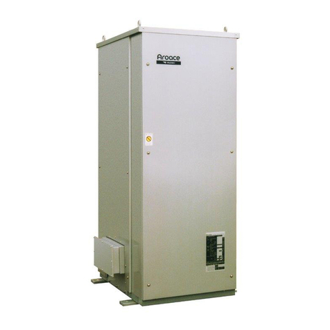
Each Yazaki absorption chiller or chiller-
heater has been evacuated, charged with
lithium bromide and water solution, and run
tested prior to leaving the factory.
Field wiring connections are located on
the left side of the unit when facing the front
of the unit, except on the WFC-SC50, which
has them located at the rear of the unit. In
all sizes, piping connections are all located at
the rear of the unit.
After the equipment has been installed, a
Yazaki Authorized Service Provider (ASP)
must check the installation and supervise or
conduct the initial startup and operation of
the unit.
CAUTION
THE YAZAKI WARRANTY WILL BE
VOIDED IF THE FOLLOWING
RESTRICTIONS ARE NOT OBSERVED:
1. DO NOT OPEN ANY SERVICE VALVES
WITHOUT A PROPER EVACUATION
ASSEMBLY ATTACHED TO THEM AS SUCH
ACTION WILL RESULT IN LOSS OF
VACUUM AND INTRODUCTION OF GASES
TO THE INTERIOR OF THE MACHINE
WHICH COULD CAUSE CORROSION.
2. ALWAYS HANDLE THE EQUIPMENT WITH
CARE AND MAINTAIN IN A NEAR-
VERTICAL POSITION DURING RIGGING. IF
THE EQUIPMENT MUST BE TILTED,
CAREFULLY FOLLOW INSTRUCTIONS
PROVIDED WITHIN THIS DOCUMENT.
3. DO NOT ATTEMPT TO START THE
SYSTEM WITHOUT SUPERVISION FROM A
YAZAKI AUTHORIZED SERVICE PROVIDER
(ASP).
MODEL DESIGNATION
WFC-S C 10
Water-Fired Chiller with Integrated Solution Pump
C - Cooling Only Design; H –Heat/Cool Design
Cooling Capacity: 10 –10 rated tons
20 –20 rated tons
30 –30 rated tons
50 –50 rated tons
ACCESSORIES
Provided with the Chiller/Chiller-Heater: Optional Accessories:
ACT-3 Maintenance Checker (1) Arotrend Remote Monitoring
Eye bolts (4) FS2 Cooling Water Flow Switch
Shims (6) {except on WFC-SC50} LON Adapter for BMS Interface
Installation Instructions (1) WFC-S Service Manual
Operating Instructions (1) WTI Inlet Chilled/Hot Water Sensor
L-Anchor Plates {with WFC-SC50 Only} Heat Medium Bypass Valve Kits
