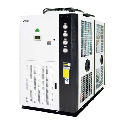
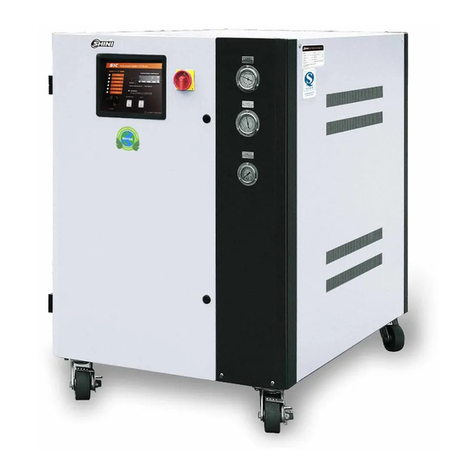
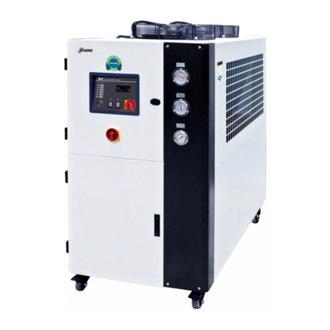
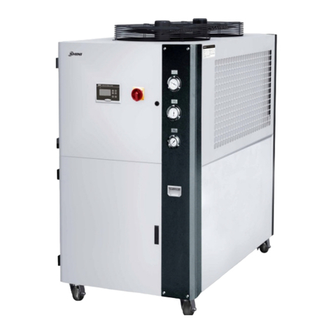
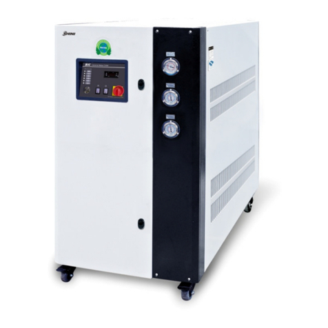
Shini SICC-A Series User manual

SICC-A Series
Air-cooledCentral WaterChiller
Date:Apr, 2013
Version: Ver.B(English)


3(61)
Contents
1. General Description..................................................................................9
1.1 CodingPrinciple.................................................................................10
1.2 Feature...............................................................................................10
1.3 TechnicalSpecifications.....................................................................12
1.3.1 SICC-A SeriesOutline Dimensions.........................................12
1.3.2 TheIllustrativeDrawingofSICC-A ModulesGrouping............15
1.3.3 Specification............................................................................19
1.4 SafetyRegulations.............................................................................20
1.4.1 NoticeItemsforSafeOperation..............................................20
1.4.2 SafetySignsand Labels..........................................................21
1.4.3 Signsand Labels.....................................................................21
1.5 ExemptionClause..............................................................................22
2. StructureCharacteristics and WorkingPrinciple.................................23
2.1.1 WorkingPrinciple.....................................................................23
2.1.2 WorkingFlowInstruction.........................................................23
2.2 ElectricalDiagram..............................................................................24
2.2.1 MainCircuit (SICC-60A)..........................................................24
2.2.2 ControlCircuit (SICC-60A)......................................................25
2.2.3 ElectricalComponentsLayout (SICC-60A)..............................26
2.2.4 ElectricalComponentsList (SICC-60A)...................................27
2.2.5 MainCircuit (SICC-90A)..........................................................28
2.2.6 ControlCircuit (SICC-90A)......................................................29
2.2.7 ElectricalComponentsLayout (SICC-90A)..............................30
2.2.8 ElectricalComponentsList (SICC-90A)...................................31
2.2.9 MainCircuit (SICC-120A)........................................................32
2.2.10 ControlCircuit (SICC-120A)....................................................34
2.2.11 ElectricalComponentsLayout (SICC-120A)............................35
2.2.12 ElectricalComponentsList (SICC-120A).................................36
3. Installation and Debugging.....................................................................37
3.1 Installation NoticeItems.....................................................................37
3.2 Select Installation Site........................................................................38

4(61)
3.3 BearingPlatform................................................................................39
3.4 Hangingand Transportingof theUnit................................................40
3.5 WaterSystemTubing.........................................................................41
3.6 Combined Installation ofModules......................................................43
3.7 EssentialsforElectricWiring..............................................................43
3.8 PowerConnection..............................................................................44
4. Operation Guide......................................................................................45
4.1 ControlPanel.....................................................................................45
4.2 TheMakeUpand Layersofthe DisplayInterface.............................45
4.2.1 TheMakeupoftheDisplayInterface......................................45
4.2.2 InterfacesShow.......................................................................45
4.3 MainWorkingInterface......................................................................46
4.3.1 InterfaceDemonstration..........................................................46
4.4 SelectingInterfaceofSystemFunction..............................................46
4.4.1 InterfaceDemonstration..........................................................47
4.4.2 InterfaceOperation..................................................................47
4.5 SystemParameterSetup Interface....................................................47
4.5.1 InterfaceDemonstration..........................................................47
4.5.2 InterfaceOperation..................................................................47
4.6 InquiryParametersofthe Module......................................................47
4.6.1 InterfaceDemonstration..........................................................47
4.6.2 InterfaceOperation..................................................................48
4.7 SystemTimeSetup............................................................................48
4.7.1 InterfaceDemonstration..........................................................48
4.7.2 InterfaceOperation..................................................................48
4.8 SystemConfiguration.........................................................................48
4.8.1 InterfaceDemonstration..........................................................48
4.8.2 InterfaceInstruction.................................................................48
4.8.3 InterfaceOperation..................................................................49
4.9 Unit RunningSettings........................................................................50
4.9.1 InterfaceDemonstration..........................................................50
4.9.2 InterfaceOperation..................................................................50
4.10ParameterSetting..............................................................................50
4.10.1 InterfaceDemonstration..........................................................50

5(61)
4.10.2 InterfaceOperation..................................................................50
4.11Unit RunningSetup............................................................................51
4.11.1 InterfaceDemonstration1.......................................................51
4.11.2 InterfaceDemonstration2.......................................................51
4.11.3 InterfaceInstruction.................................................................51
4.11.4 InterfaceOperation..................................................................51
4.12InquiryModuleTemperature..............................................................52
4.12.1 InterfaceDemonstration..........................................................52
4.12.2 InterfaceInstruction.................................................................52
4.12.3 InterfaceOperation..................................................................52
4.13InquiryFaults......................................................................................52
4.13.1 InterfaceDemonstration..........................................................52
4.13.2 InterfaceInstruction.................................................................53
4.14TheConfiguration ofModuleUnit.......................................................53
5. Trouble-shooting.....................................................................................57
6. Maintenance and Repair.........................................................................58
6.1 DailyRepair and CheckItems............................................................59
6.2 MonthlyPeriodicalCheckingItems....................................................59
6.3 MonthlyPeriodicalChecking..............................................................59
6.4 MaintenanceSchedule.......................................................................60
6.4.1 About theMachine...................................................................60
6.4.2 Installation &Inspection...........................................................60
6.4.3 DailyChecking.........................................................................60
6.4.4 WeeklyCheck..........................................................................60
6.4.5 MonthlyCheck.........................................................................60
6.4.6 TrimonthlyChecking................................................................60
6.4.7 Check Half-yearly....................................................................61
6.4.8 YearlyChecking.......................................................................61
6.4.9 3yearChecking.......................................................................61
TableIndex
Table1-1 Specification...................................................................................19
Table2-1 ElectricalComponentsList (SICC-60A).........................................27

6(61)
Table2-2 ElectricalComponentsList (SICC-90A).........................................31
Table2-3 ElectricalComponentsList (SICC-120A).......................................36
PictureIndex
Picture1-1 SeriesOutline Dimensions(SICC-60A).......................................12
Picture1-2 SeriesOutline Dimensions(SICC-90A).......................................13
Picture1-3 SeriesOutline Dimensions(SICC-120A).....................................14
Picture1-4 The IllustrativeDrawingofSICC-A ModulesGrouping................15
Picture1-5 SICC-60A RefrigeratingPerformanceCurves.............................16
Picture1-6 SICC-90A RefrigeratingPerformanceCurves.............................17
Picture1-7 SICC-120A RefrigeratingPerformanceCurves...........................18
Picture2-1 WorkingPrinciple.........................................................................23
Picture2-2 MainCircuit (SICC-60A)..............................................................24
Picture2-3 ControlCircuit (SICC-60A)...........................................................25
Picture2-4 ElectricalComponentsLayout (SICC-60A)..................................26
Picture2-5 MainCircuit (SICC-90A)..............................................................28
Picture2-6 ControlCircuit (SICC-90A)...........................................................29
Picture2-7 ElectricalComponentsLayout (SICC-90A)..................................30
Picture2-8 MainCircuit 1(SICC-120A).........................................................32
Picture2-9 MainCircuit 2(SICC-120A).........................................................33
Picture2-10 ControlCircuit (SICC-120A).......................................................34
Picture2-11 ElectricalComponentsLayout (SICC-120A)..............................35
Picture3-1 InstallationSpace........................................................................38
Picture3-2 PlatformInstallation.....................................................................39
Picture3-3 Hangingand TransportingoftheUnit..........................................40
Picture3-4 SameDirection Way1.................................................................42
Picture3-5 SameDirection Way2.................................................................42
Picture3-6 CombinedInstallationof Modules................................................43
Picture3-7 EssentialsforElectricWiring.......................................................44
Picture4-1 ControlPanel...............................................................................45
Picture4-2 InterfacesShow...........................................................................46
Picture4-3 MainWorkingInterface................................................................46
Picture4-4 SelectingInterfaceof SystemFunction........................................47

7(61)
Picture4-5 SystemParameterSetupInterface..............................................47
Picture4-6 InterfaceDemonstration...............................................................47
Picture4-7 InterfaceDemonstration...............................................................48
Picture4-8 SystemConfiguration...................................................................48
Picture4-9 Unit RunningSettings..................................................................50
Picture4-10 ParameterSetting......................................................................50
Picture4-11 Unit RunningSetup 1.................................................................51
Picture4-12 Unit RunningSetup 2.................................................................51
Picture4-13 InquiryModuleTemperature......................................................52
Picture4-14 Sub-interface1..........................................................................52
Picture4-15 Sub-interface2..........................................................................53
Picture4-16 Sub-interface3..........................................................................53

8(61)

9(61)
1. General Description
Read thismanualcarefullybeforeoperationtopreventdamageofthe
machine orpersonalinjuries.
SICC-Aseriesareapplicableforcoolingmouldstoreduceproductsmoldingcycle,
alsotheyareavailableinthecoolingof equipmentsinordertomaintainanormal
temperature.Besides,theyaresuitableforotherindustrieswiththe needof
cooling.
Model: SICC-90A

10(61)
1.1CodingPrinciple
S
I
CC
-
xxxA
-
xx
Refrigerant:
Nocode=R22R1=R407CR2=R410A
First ThreeCodes:Refrigerating Capacity(kW)
A=Air Cooled
Shini CentralWater Chillers
CE=CEConformity
Note:
1.2Feature
1)Standardconfiguration
●Modularized design makesit easiertocombinemoduleunits1to15.
Coolingcapacitycan beenlarged byincreasingthe numberofmodulesor
chooseappropriatemodulestoconnect toexistingsystem.
●Thewaterrouteof the modulescan be linked vialinkingone moduletothe
inlet/outlet watertube.Noneed toinstall theinlet/outletwatertubeforeach
modulealone.Thesoft rubbertubeisused toconnectthe modules, thusitis
veryconvenient toconstruct.
●Adoptsimportedcomponentslikescroll compressor, expansionvalvewhich
ensurestableperformance.The wholeunit will not stopdue toone module
failure.
●Whenthe wholeunit isrunning, the microcomputerwill autoadjust the
performanceof eachmoduleoropen /shutrespectivemoduleunit
accordingtosystemload.Themoduleunitadoptsdoublecompressorsand
itspoweradjustablerangeisenlarged aftercombinationtosaveuppower
wheneverpossible.
●Wiredcontrolsystemenablesthe mainunitanditscontrollertobeseparated
fromeachother.
2)Accessoryoption
●OptionalRS485 communication realizesthe remotemonitoringand network
function.

11(61)
All serviceworkshouldbe carried out byaperson withtechnicaltrainingor
correspondingprofessionalexperience.The manualcontainsinstructionsforboth
handlingand servicing.Chapter6, whichcontainsserviceinstructionsintendedfor
serviceengineers. Otherchapterscontaininstructionsforthedailyoperator.
Anymodificationsofthemachinemustbe approved bySHINI inordertoavoid
personalinjuryand damagetomachine.Weshall not beliableforanydamage
causedbyunauthorized changeof themachine.
Ourcompanyprovidesexcellent after-salesservice. Shouldyou haveanyproblem
duringusingthemachine,pleasecontactthecompanyorthelocalvendor.
HeadquarterandTaipeifactory
Tel:(886)226809119
ShiniPlastics Technologies(Dongguan), Inc
Tel:(86)769 81116600
ShiniPlastics TechnologiesIndiaPvt.Ltd.
Tel:(91)250 3021166

12(61)
1.3Technical Specifications
1.3.1SICC-A SeriesOutline Dimensions
Picture1-1 Series OutlineDimensions (SICC-60A)

13(61)
Picture1-2 Series OutlineDimensions (SICC-90A)

14(61)
Picture1-3 Series OutlineDimensions (SICC-120A)

15(61)
1.3.2TheIllustrativeDrawingofSICC-A ModulesGrouping
Picture1-4 TheIllustrativeDrawing ofSICC-AModules Grouping

16(61)
Picture1-5 SICC-60ARefrigerating Performance Curves

17(61)
Picture1-6 SICC-90ARefrigerating Performance Curves

18(61)
Picture1-7 SICC-120ARefrigerating PerformanceCurves

19(61)
1.3.3Specification
Table1-1 Specification
kW
kcal/hr
kW
kW
kg
60
51,600
8.5 2
0.07 2
15
10.3
27
5
1.68
26,000
2163
975
2230
SICC-60A
dB(A) 71
720
760
kW
A
A
19
33
140
77,400
90
2163
1170
2230
1.68
39,000
15.5
39.2
5
13.6 2
0.07 2
18
SICC-90A
72
820
870
28
48
175
103,200
120
2163
1825
2230
3.72
52,000
20.6
49
5
18.8 2
0.09 2
36
SICC-120A
74
1300
1350
37
61
230
m3/hr
inch
kPa
kW
m3/hr
mm
mm
mm
kg
kg
---
---
---
---
---
Model
Type
CrankCase
Heater
Power
Type
Filling
Quantity
Type
Cooling
Flow
Pressure
Loss
Water
Coupler
Type
Blower
Power
Air
Quantity
Items
3Φ,400/ 460VAC,50 / 60Hz
TotalPower
Running
Current
Startup Current
HermeticScroll
Closed Shell andTube Evaporator
Tube-finAir-cooledCondenser
Refrigeration
Capacity
Power
CompressorRefrigerantEvaporatorCondenser
Height(H)
Width(W)
Depth(D)
Machine
Dimensions
Before
Packing
After
Packed
NoiseLevel
dB(A)
Weight
R22(R407COptionalyAvailable)
1kW=860kcal/hr1RT=3,024 kcal/hr10,000 Btu/hr=2,520 kcal/hr
Measures
Exchange
Note: 1) The coolingpower referstothe following conditions:We reservetheright tochange
outdoor drybulb temperature35℃, temperatureatspecificationswithout prior notice.
cooling waterinlet is12℃and 7℃atitsoutlet.
2) ChangetouseR407Cenvironment friendlyrefrigerant
is available asoption, but therefrigerationcapacitycan
be decreasedby5%.

20(61)
1.4SafetyRegulations
Strictlyabide bythe followingsafetyregulationstoprevent damageofthe
machine orpersonalinjuries.
1.4.1NoticeItemsforSafeOperation
Read the followingregulationsbeforeinstallation orusingunderthe
consideration ofsafety.
1)Donot dropwaterinthe electricalpart toavoidinsulation damage.
2)Putdeviceconnecttoground accordingtoelectrician operatingregulation to
avoidcreepage.
3)Anytubesorelectricaldevicemount onair conditionermustbe installed by
professionaltechnicians.
4)Pleaseinstall unitsinflatandventilativeplaceand keepsuitabledistances.
5)Keepawayfromfiresource,suchaswaterheater.gasandelectricstove.
6)Avoidbeingexposedtoweather.
7)Constructaccordingtoinstallationinstructionsand notice.
8)Thistype ofair-conditionerisdesigned foradults.Keepchildren awayfromit.
9)Anydeedstryingtochangeitsspecificationaredangerous.
10)Don'tuseevaporablesolvents,oil ortoluene toavoidaccidents.
11)Ensurethismachinenot topress on the electricalwirestoavoidcreepage
and burning.
12)Donot touchthemachinewithwet handsincaseofaccident.
13)Underno circumstancesshouldyou trytorepair the waterchiller. Because
the untrained maycausegreaterdamagesorfailures.Pleaseinquirelocal
serviceagents.
14)Donotpourwaterordetergent onthesurfaceofmachine when cleaningit.
Pleasewipe it withclothorneutraldetergent.
15)Donotplacethingson the uppersurfaceofthe waterchillerinordertoavoid
dangerduringrunning.
16)Connectthewaterchillertospecialelectricitysupply.It isforbidden toshare
circuit withotherdevices.
17)Donotchangeorrepairthe electricalwireswithout authority.
18)Donotinsertanythingintoair outlet of thewaterchillertoavoiddamageor
danger.
This manual suits for next models
3
Table of contents
Other Shini Chiller manuals
Popular Chiller manuals by other brands

Cooper & Hunter
Cooper & Hunter CH-FK18SWK2 Installation & owner's manual

Cooper & Hunter
Cooper & Hunter CH-CH8SNM Service manual

innove
innove Glass Chiller user manual

CIAT
CIAT LJA Series User brochure

Fulgor Milano
Fulgor Milano FBC 4005 TC X manual

Wesper
Wesper SLS 1202 Installation and maintenance manual