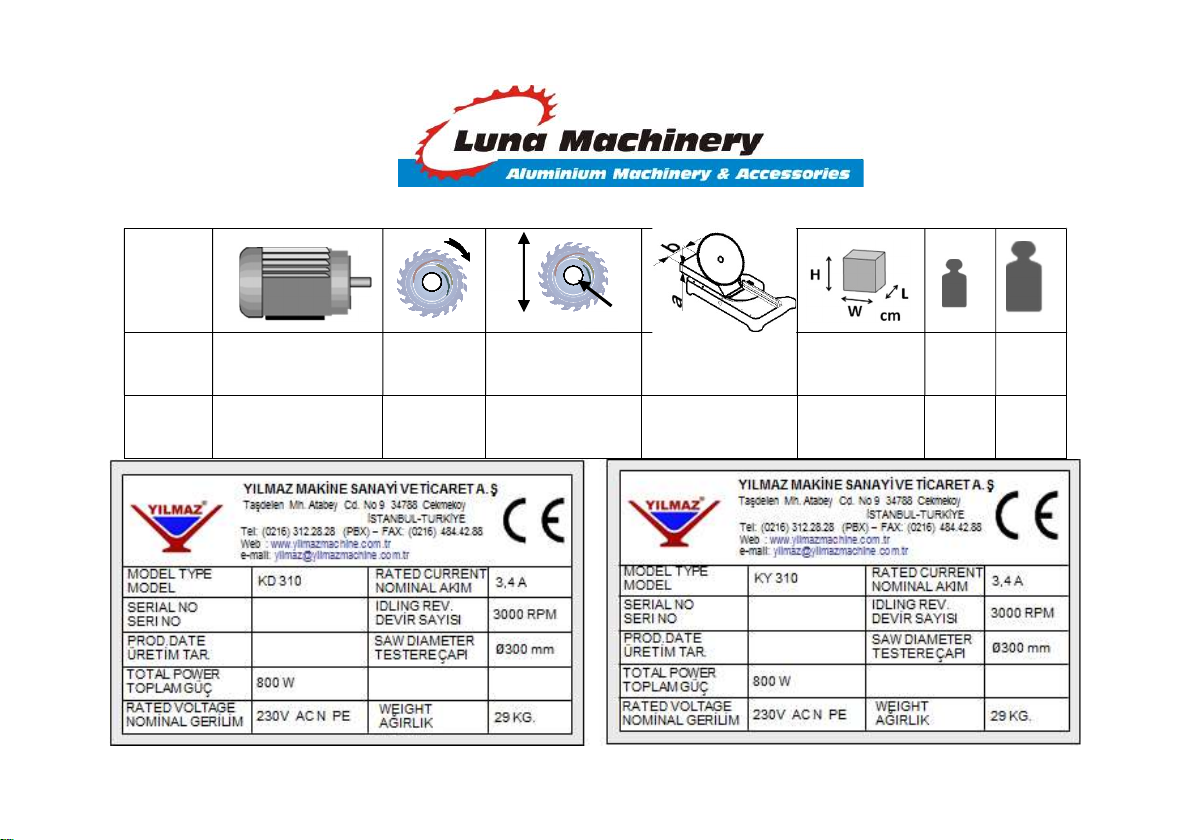
YILMAZ Luna Machinery KD 310 User manual

1
d
D
KY KD 310 - TECHNICAL FEATURES
kg kg
KD 310 800 W 50 Hz
230 V AC N PE
3000
dev/dak.
RPM
D = 300 mm
d = 30 / 32 mm --
W
= 63
L = 52
H = 48
26 29
KY 310 800 W 50 Hz
230 V AC N PE
3000
dev/dak.
RPM
D = 300 mm
d = 30 / 32 mm
a : 50 mm
b : 130 mm
W
= 63
L = 52
H = 48
26 29

2
CUTTING DIAGRAM

3
DIMENSIONS

4
PART LIST
RESİM-FIGURE-РИСУНОК 1

5
RESİM-FIGURE-РИСУНОК 2

6
RESİM-FIGURE-РИСУНОК 3

7
NO
номер
STOK KODU
/ CODE
ПОРЯДОК КОД
ADET
/
QTY
КОЛИЧЕСТВО
NO
номер
STOK KODU
/ CODE
ПОРЯДОК КОД
ADET
/
QTY
КОЛИЧЕСТВО
1
2TU012610
-
0
151
1
124
2TU011110
-
1697
2
2
1PL030000
-
0024
4
129
1PL010000
-
0049
1
5
3UA250030
-
0009
1
132
3UA770030
-
0013
1
8
1PL010000
-
0
011
1
135
2TU011110
-
0146
1
12
3UA030030
-
0001
1
138
1SK010000
-
0002
1
14
2TU012610
-
0020
1
139
2TU011710
-
0004
1
26
2TU011110
-
0145
4
140
1SC021000
-
0027
1
29
2TU012610
-
0079 (KD 310)
1
144
3UA250030
-
0002
1
29
2TU012610
-
0087 (KY 310)
1
147
1PL010000
-
0057
1
30
2TU011441
-
1542
(KY 310)
1
148
1YY021000
-
0004
2
35
3UA040030
-
0013 (KY 310)
1
149
2TU011210
-
0177
2
45
3UA090030
-
0004
1
57
2TU012610
-
0019
1
64
3UA770030
-
0020
1
77
3UB030030
-
0001
1
85
3UB030030
-
0002
1
92
1PL010000
-
0107
1
93
1EL010
000
-
0011
1
115
1PL010000
-
0048
1
123
2TU012610
-
0081
1

8
HOLE DIMENSIONS FOR CONVEYOR CENNECTION

9
PARÇA
NO
PART NO
НОМЕР
RESİM
FIGURE
РИСУНОК
STOK KODU / CODE
ПОРЯДОК КОД
5
3UA250030-0009
8
1PL010000-0011
12
3UA030030-0001
14
2TU012610-0020
26
2TU011110-0145

10
29
2TU012610-0079 (KD 310)
2TU012610-0087 (KY 310)
35
3UA040030-0013 (KY 310)
45
3UA090030-0004
57
2TU012610-0019
64
3UA770030-0020
77
3UB030030-0001

11
85
3UB030030-0002
92
1PL010000-0107
93
1EL010000-0011
1EL020000-0022 (KD/KY 310B)
1EL040000-0500 (KD/KY 310B)

12
1EL190000-0400 (KD/KY 310B)
1EL020000-0012 (KD/KY 310B)
1EL180000-0001
115
1PL010000-0048
123
2TU012610-0081

13
129
1PL010000-0049
132
3UA770030-0013
138
1SK010000-0002
139
2TU011710-0004
144
3UA250030-0002

14
147
1PL010000-0057
148
1YY021000-0004

15
ENGLISH
CONTENTS
1. General information
1.1. Introduction
1.2. Service Information
2. Safety
2.1. Safety Symbols and Their Meanings
2.2. Accidents Prevention
2.3. General Safety Information
3. Machine’s Description
4. Transport of the Machine
5. Installation of the Machine
5.1. Preparation
5.2. Connecting to Power Source
6. Machine’s Safety Information
7. Operation
7.1 Preparation
7.2 Operation
7.3 Angular cutting
7.4 Angular cutting (KY 310)
8. Maintenance, Service and Repair
8.1 Maintenance
8.2 Changing the cutting tool
9. Warranty conditions

16
1. GENERAL INFORMATION
1.1. Introduction
The user’s manual given by the manufacturer contains necessary information about the machine parts. Each machine
operator should read these instructions carefully, and the machine should be operated after fully understanding them.
Safe and efficient use of the machine for long term depends on understanding and following the instructions contained in
this manual. The technical drawings and details contained in this manual constitute a guide for the operator.
1.2. Service Information
In case of any technical problem please contact your nearest YILMAZ dealer, or YILMAZ head office through the above
mentioned phone, fax or e-mail address.
Technical labels with the model description of the machine are fixed onto the front side of each machine.
The machine’s serial number and manufacturing year are stipulated on the technical label.
Average life usage of production is 10 years. If you have any further failure and complaint, please inform to our
below mentioned technical service by verbal or written

17
AUTHORIZED TECHNICAL SERVICE CENTER ADDRESS
TAŞDELEN MH. ATABEY CD. No 9 34788 ÇEKMEKÖY – İSTANBUL / TÜRKİYE
Tel 0216 312 28 28 Pbx.
Fax 0216 484 42 88
E-mail [email protected] / [email protected].au
Web www.yilmazmachine.com.tr / www.lunamac.com.au
For minimize the documantation, It is wery necessary to mention below details at the agreements signed with suppliers and
dealers of the purchased machines
Machine model Voltage and frequency
Machine’s serial number Date of purchase
Description of the machine fault Name of dealer where machine was purchased
Average daily operation period

18
2. SAFETY
2.1. Safety Symbols and Their Meanings
Read the user guide
Ensure safe working position, always keep your
balance.
Wear ear protectors
Elektrical excitation
Wear safety goggles
Don’t place your hands between parts in motion..
If the power cable should be damaged
during operation, don't touch and unplug it.
Never use damaged power cables.
High temperature warning
During saw blade change operations, use
protective gloves
Keep your fingers clear of the movable parts of
the glide arm.
The above symbol DANGER WARNING,
warns you against specific dangers, and you
have definitely to read them..
The IMPORTANT symbol above is one telling to
apply special care and to be careful at carrying
out the specified operation

19
2.2. Accidents Prevention
2.2.1 Our machines are manufactured in accordance with CE safety directives, which cover national and international
safety directives.
2.2.2 It is the task of the employer to warn his staff against accident risks, to train them on prevention of accidents, to
provide for necessary safety equipment and devices for the operator’s safety.
2.2.3 It is the task of the employer to warn his staff against accident risks, to train them on prevention of accidents, to
provide for necessary safety equipment and devices for the operator’s safety.
2.2.4 Machine should be operated only by staff members, who have read and understood the contents of this manual.
2.2.5 All directives, recommendations and general safety rules contained in this manual have to be observed fully.
The machine cannot be operated in any way for purposes other than those described herein. Otherwise, the
manufacturer shall not be deemed responsible for any damages or injuries. And such circumstances would lead
to the termination of the warranty
2.3. General Safety Information
2.3.1 The power cable should be led in such a way that nobody can step on it or nothing can be placed on it. Special
care has to be taken regarding the inlet and outlet sockets
2.3.2 Don’t overload machines for drilling and cutting. Your machine will operate more safely with power supply in
accordance with the stipulated values.
2.3.3 Use correct illumination for the safety of the operator. (ISO 8995-89 Standard The lighting of indoor work
system)

20
2.3.4 Do not leave any things on the machine.
2.3.5 Don’t use any materials other than those recommended by the manufacturer for cutting operations on the
machine.
2.3.6 Ensure that the work piece is clamped appropriately by the machine's clamp or vice
2.3.7 Ensure safe working position, always keep your balance.
2.3.8 Keep your machine always clean for safe operation. Follow the instructions at maintenance and replacement of
accessories. Check the plug and cable regularly. If damaged, let it replace by a qualified electrician. Keep
handles and grips free of any oil and grease.
2.3.9 Unplug first, before conducting and maintenance works.
2.3.10 Ensure that any keys or adjustment tools have been removed before operating the machine..
2.3.11 If you are required to operate the machine outside, use only appropriate extension cables.
2.3.12 Repairs should be carried out by qualified technicians only. Otherwise, accidents may occur.
2.3.13 Before starting a new operation, check the appropriate function of protective devices and tools, ensure that they
work properly. All conditions have to be fulfilled in order to ensure proper operation of your machine. Damaged
protective parts and equipment have to be replaced or repaired properly (by the manufacturer or dealer).
2.3.14 Don’t use machines with improper functioning buttons and switches
2.3.15 Don’t keep flammable, combustive liquids and materials next to the machine and electric connections.
This manual suits for next models
1
Table of contents
Other YILMAZ Cutter manuals