Yingli Solar YGE G/G 60CL/F Series User manual

Yingli Solar G/G Modules, Installation and User Manual page 1
This manual applies to G/G modules (“G/G modules”,
also commonly known as Double Glass Modules.
Hereinafter referred to as PV modules) manufactured
by Yingli Green Energy Holding Co. Ltd. (“Yingli Solar”),
and is explicitly written for qualified professionals
(“Installer” or “Installers”), including without limitation
licensed electricians and RAL Certified PV Installers.
INTRODUCTION
Thank you for choosing Yingli Solar as your PV module provider. We appreciate
your business! This manual contains important information pertaining to the
electrical and mechanical installation and maintenance of PV modules, and
contains safety information that you must read carefully and be familiar with
before handling, installing, and/or maintaining Yingli Solar PV modules.
Yingli Solar does not assume responsibility and expressly disclaims liability for
losses, damages, or expenses arising out of, or in any way connected with this
Installation and User Manual. Yingli Solar assumes no responsibility for any
infringement of patents or other rights of third parties, which may result from
using Yingli Solar PV modules. No license is granted expressly or by implication
or under any patent or patent rights. The information in this manual is believed
to be reliable, but does not constitute an expressed or implied warranty. Yingli
Solar reserves the right to make changes to its PV modules and other products,
their specifications or this manual without prior notice.
Yingli Solar and its subsidiaries are not liable for any damages caused by
inappropriate installation, use or maintenance of Yingli Solar PV modules,
including without limitation damages, losses and expenses caused by non-
observance of the instructions of this manual or caused by or in connection with
products of other manufacturers.
Yingli Solar PV modules are designed to meet the requirements for the standards
IEC 61215 and IEC 61730, application class A. Modules rated for use in this
application class may be used in systems operating at greater than 50 V DC
or 240 W, where general contact access is anticipated. Modules qualified for
safety through IEC 61730-1 and IEC 61730-2 and within this application class are
considered to meet the requirements for safety class II. In the course of the PV
module certification process, the compliance of this manual with the certification
requirements has been verified by an independent certification laboratory.
This Installation and User Manual is available in dierent languages. In cases of
discrepancy between versions, the English language version shall control.
Failure to comply with the requirements listed in this manual will invalidate the
Limited Warranty for PV modules as provided by Yingli Solar at the time of sale
to the direct customer. Additional recommendations are provided to enhance
safety practices and performance results. Please provide a copy of this manual
to the PV system owner for their reference, and inform them of all relevant
aspects of safety, operation and maintenance.
SAFETY
General
You must understand and follow all applicable local, state and federal
regulations and standards for building construction, electrical design, fire and
safety, and must check with local authorities to determine applicable permitting
requirements before attempting to install or maintain PV modules.
Rooftop PV systems should only be installed on houses that have been formally
analyzed for structural integrity, and confirmed to be capable of handling the
additional load of PV system components, including PV modules, by a certified
building specialist or engineer.
For your safety, do not attempt to work on a rooftop until safety precautions
have been identified and taken, including without limitation
fall protection measures, ladders or stairways, and personal
protective equipment.
For your safety, do not install or handle PVmodules under
adverse conditions, including without limitation strong or gusty winds, and wet
or frosted roof surfaces.
PV modules are photovoltaic products made of tempered glass, encapsulant,
ribbon, cells and junction boxes. Figure 1 is an illustration of the PV module
components.
Figure 1: Module components and cross-section of the laminated assembly
Electrical
PV modules can produce current and voltage when exposed to light of any
intensity. Electrical current increases with higher light
intensity. DC voltage of 30 Volts or higher is potentially lethal.
Contacting live circuitry of a PV system operating under light
can result in lethal electric shock.
De-energize PV modules by removing them entirely from light
or by covering their front and rear surfaces with an opaque material. Regard the
safety regulations for live electrical equipment when working with modules that
are exposed to any light. Use insulated tools and do not wear metallic jewelry
while working with PV modules.
In order to avoid arcing and electrical shock, do not disconnect electrical
connections under load. Faulty connections can also result in arcing and
electrical shock. Keep connectors dry and clean, and ensure that they are in
proper working condition. Never insert metallic objects into the connectors, or
Connector CableJunction box Cell
YINGLISOLAR.COM
YINGLI SOLAR G/G MODULES
Installation and User Manual
Revision date July 15th, 2018 | Applicable for IEC certified products | The second edition
File name: Corporate Logo with Tagline / Vertical.ai

Yingli Solar G/G Modules, Installation and User Manual page 2
modify them in any way in order to secure an electrical connection.
Do not touch or handle PV modules with broken glass or separated frames,
unless the modules are disconnected and you are wearing proper personal
protective equipment. Avoid handling PV modules when they are wet unless
cleaning the PV modules as directed in this manual. Never touch electrical
connections that are wet without protecting yourself with insulated gloves.
Transport and Handling
Yingli Solar PV modules must be transported in the supplied packaging only,
and kept in the packaging until they are ready to be installed. At time of receipt,
please verify that the delivered product is in fact the product ordered. The
product name, subname and serial number of each laminate are clearly marked
on the outside of each packing box.
Protect pallets against movement and exposure to damage during transportation.
Do not exceed the maximum allowable height of pallets to be stacked, as
indicated on the pallet packaging. Secure pallets from falling over. If pallets are
stored temporarily outside please place a protective covering over the pallet to
protect it from direct weathering and do not stack pallets.
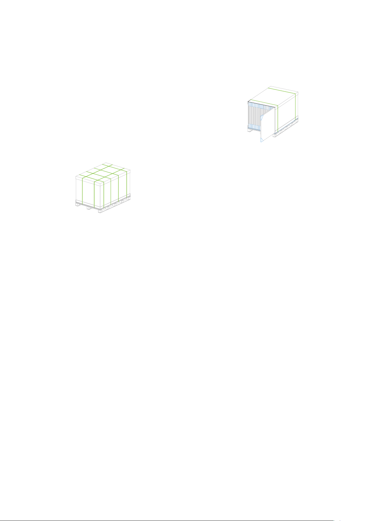
Figure 2: Pallet of PV modules
At the installation site, take care to keep modules and their electrical contacts
clean and dry before installation. If connector cables are left in damp conditions
then the contacts may corrode. Any module with corroded contacts should not
be used. Yingli Solar PV modules are heavy, and should be handled with care,
so non-slip gloves are required when handling and installation. Please never
use the junction box or cables as a grip. Do not exert mechanical stress on the
cables. Never steps on PV modules or drop or place heavy objects on them.
Be careful when placing PV modules on hard surfaces, and secure them from
falling. Broken glass can result in personal injury. PV modules with broken glass
cannot be repaired and must not be used. Broken or damaged PV modules must
be handled carefully and disposed of properly.
For unpacking frameless PV modules from supplied packaging, firstly, remove
the pallet lid after removing security straps, and then remove the carton, paper
corner and foam rubber. Remove PV modules one at a time by sliding them up
the channel in the package with both hands (see Figure 3). You may need to
secure the remaining PV modules in the pallet packaging to prevent them from
falling over.
Figure 3: Packaging structure of frameless PV modules
For unpacking framed PV modules ensure that the pallet stands firm and that it
isn´t inclined in such a way that modules can slide out during
the unpacking process (opening side shouldn´t face downwards). Cut the two
longitudinal and the two inner transverse security straps. Carefully cut and
remove the cardboard of one short side of the box including the corresponding
part of the upper lid and the bottom lid (see Figure 4). Pay attention to not
damage the modules during the cutting process. Thirdly cut the two inner
security straps around the modules, remove the two paper corners and pull
slowly out the modules one by one. You may need to secure the remaining PV
modules in the pallet packaging to prevent them from falling over.
Figure 4: Cutting cardboard and pull out modules
Check PV modules for damage due to transportation before installation. Do not
install damaged modules. Please contact the company you have purchased the
Yingli Solar PV modules for information or complaints.
PV module surfaces are susceptible to damage that could aect the performance
or safety of the module. Do not damage or scratch the PV module surfaces, and
do not apply paint or adhesive to any of the surfaces, including the frame. For
your safety, do not disassemble or modify the modules in any way. Doing so may
degrade performance or cause irreparable damage and will void any applicable
warranties.
If it is necessary to store PV modules prior to installation, the PV modules
should remain inside the packaging and protected from exposure that could
compromise the durability of the packaging.
Fire
Yingli Solar PV modules have a class A fire resistance rating in accordance with
the IEC 61730-2 certification, while the materials of modules for class A please
refer to the test report and CDF document. When PV modules are mounted
on the rooftops, the roof must have a fire resistant covering suitable for this
application. PV modules are electrical generating devices that may aect the
fire safety of a building.
The use of improper installation methods and/or defective parts may result
in the unexpected occurrence of an electrical arc during operation. In order to
mitigate the risk of fire in this event, PV modules should not be installed near
flammable liquids, gases or locations with hazardous materials.
In the event of a fire, PV modules may continue to produce a dangerous
voltage, even if they have been disconnected from the inverter, partly or entirely
destroyed, or the system wiring has been compromised or destroyed. In the
event of fire, inform the fire crew about the particular hazards from the PV
system, and stay away from all elements of the PV system during and after a fire
until the necessary steps have been taken to make the PV system safe.
APPLICATION INFORMATION
Application Restrictions
Yingli Solar PV modules must be mounted on appropriate structures, positioned
on buildings, the ground, or other places suitable for PV modules (e.g. carports,
building facades or PV trackers). PV modules must not be mounted on moving
vehicles of any kind. Yingli Solar PV modules must not be installed in locations
where they could be submerged in water.
Yingli Solar PV modules must not be sited in locations where aggressive
substances, such as salt or salt-water, or any other type of corrosive agent, could
aect the safety and/or performance of the PV modules.

Yingli Solar G/G Modules, Installation and User Manual page 3
Artificially concentrated light must not be directed on the front and rear surfaces
of PV modules.
Design Recommendations
Yingli Solar recommends that PV modules shall be mounted at a minimum tilt
angle of 10 degrees to allow for proper self-cleaning from normal rain showers.
PV modules are recommended to be installed at an optimized tilt angle to
maximize the energy output. It is roughly equal to the latitude of the project
site as a rule of thumb, facing the equator. But always to design based on local
situations to find out the optimum one.
Partial or complete shading of a PV module or modules can significantly reduce
system performance. Yingli Solar recommends minimizing the amount of shade
throughout the year to increase the amount of energy produced by the PV
modules.
Lightning protection is recommended for PV systems that are to be installed in
locations with high probability of lightning strikes.
High system voltages could be induced in the event of an indirect lightning
strike, which could cause damage to PV system components. The open area
of wire loops should be minimized (see Figure 5), in order to reduce the risk of
lightning induced voltage surges.
Figure 5: Wire loop design recommendation
Climate Conditions
PV modules may be installed in the following conditions for more than 30 years.
In addition to the required IEC certification, PV modules have also been tested to
verify resistance to ammonia fumes that may be present around barns sheltering
cattle, as well as suitability for installation in humid (coastal) areas and areas of
high sand storms.
Table 1: Environment of installation
ELECTRICAL INSTALLATION
Electrical Configuration
Under normal conditions, a PV module is likely to experience conditions that
produce more current and/or voltage than reported at Standard Test Conditions
(Irradiance: 1000 W/m2, 25°C cell temperature and AM 1.5). The short-circuit
current (ISC) should be multiplied by a factor of 1.25 based on the highest
ambient temperature recorded, and the open-circuit voltage (VOC) should be
multiplied by a factor of up to 1.25 based on the lowest ambient temperature
recorded for the installation location when determining component voltage
ratings, conductor current ratings, fuse sizes, and size of controls connected to
the PV output.
This maximum voltage should not be exceeded at any time and, as the voltage of
the module increases, above datasheet values, at operating temperatures below
25°C, then these need to be taken into account when designing a PV system.
Voltages are additive when PV modules are connected directly in series, and
module currents are additive when PV modules are connected directly in parallel
(see Figure 6). PV modules with dierent electrical characteristics must not be
connected directly in series. The use of unsuitable third-party electronic devices
connected to PV modules may lead to mismatching, and must be installed
according to the manufacturer’s specified instructions.
Figure 6: Electrical diagrams of series and parallel wiring
The maximum voltage of the system must be less than the maximum certified
voltage, 1500V typically, and the maximum input voltage of the inverter and
of the other electrical devices installed in the system. To ensure that this is the
case, the open circuit voltage of the array string needs to be calculated at the
lowest expected ambient temperature for the location. This can be done by
using the following formula.
Max System voltage ≥N * Voc * [1 + βVoc * (Tmin-25)]
When the modules connect in parallel, the output current will be equal to the
sum of each branch current. It is suggested that every series module string
should be fused prior to be connected with other strings. Please refer to the
applicable regional and local codes for additional fuse requirements.
An appropriately rated overcurrent protection device must be used when the
reverse current could exceed the value of the maximum fuse rating of the
module. An overcurrent protection device is required for each series string if
more than two series strings are connected in parallel.
Cables and Wiring
Yingli Solar PV modules are provided with two (2) stranded, sunlight resistant
outputcablesthatareterminatedwithPVconnectors readyformostinstallations.
The positive (+) terminal has a female connector while the negative (-) terminal
has a male connector. The module wiring is intended for series connections [i.e.
female (+) to male (-) interconnections, as shown in Figure 7], but can also be
used to connect suitable third-party electrical devices that may have alternative
wiring configurations so long as the manufacturer’s instructions are followed.
Use field wiring with suitable cross-sectional areas that are approved for use at
the maximum short-circuit current of the PV module. Yingli Solar recommends
to use only sunlight resistant waterproof cables qualified for direct current (DC)
wiring in PV systems. The minimum wire size should be 4 mm2.
Ideal Wiring Loop Greater Risk of Lightning
Induced Voltage Surge
Series Wiring (Voltage Additive)
Parallel Wiring (Current Additive)
Operating temperature -40°C to +85°C
Storage temperature -20°C to +50°C
Humidity < 85%RH
Altitude ≤2000m
Notes:
The modules have been evaluated by TUV according to IEC61215 for a maximum positive design loading
of 3600 Pa, and negative design loading 1600 Pa, with 1.5 times safety factor.
The mechanical load bearing is dependent upon the mounting methods used and failure to follow the
instructions in this manual may result in dierent capabilities to withstand snow and wind loads.
The system installer must ensure that the installation methods used meet these requirements and any
local codes and regulations.
Where NNumber of modules in series
Voc Open circuit voltage of each module (refer to product label or datasheet)
βVoc Thermal coefcient of open circuit voltage for the module (refer to datasheet)
Tmin The lowest ambient temperature

Yingli Solar G/G Modules, Installation and User Manual page 4
Table 2: Required minimum field wiring specifications
Testing standard Wire size Temperature rating
Required minimum eld wiring EN 50618 4 mm2-40 ºC to +90 ºC
Cables should be fixed to the mounting structure in such a way that mechanical
damage of the cable and/or the module is avoided. Do not apply stress to
the cables, the minimum cable bending radius should be 40 mm. For fixing,
use appropriate means, such as sunlight resistant cable ties and/or wire
management clips specifically designed to attach to the mounting structure.
While the cables are sunlight resistant and waterproof, where possible, avoid
direct sunlight exposure and water immersion of the cables.
Connectors
Keepconnectorsdryand clean,and ensurethatconnector
caps are hand tight before connecting the modules. Do
not attempt making an electrical connection with wet,
soiled or otherwise faulty connectors. Avoid sunlight
exposure and water immersion of the connectors. Avoid
connectors resting on the ground or roof surface.
Faulty connection can result in arcs and electrical shock. Check that all electrical
connections are securely fastened. Make sure that all locking connectors are
fully engaged and locked.
Modules must not be interconnected using connectors from dierent
manufacturers and/or of dierent types. If modules having such dierent
connectors need to be interconnected, a qualified professional may replace
connectors according to the manufacturers’ specified instructions such that an
interconnection can be made with connectors from the same manufacturer and
the same type.
Figure 7: Connector of the plugs
Bypass Diodes
The junction boxes used with Yingli Solar PV modules contain bypass diodes
wired in parallel with the PV cell strings. In the case of partial shading, the
diodes bypass the current generated by the non-shaded cells, thereby limiting
module heating and performance losses. Bypass diodes are not overcurrent
protection devices.
Bypass diodes divert current from the cell strings in the event of partial
shading. See Figure 8 for a diagram showing how the cell strings are electrically
connected with the diodes. In the event of a known or suspected diode failure,
installers or maintenance providers should contact the company which the PV
modules were purchased from. Never attempts to open the junction box of a
Yingli Solar PV module yourself.
Figure 8: Electrical circuitry of cells and bypass diodes
PV Array Grounding
For optimal performance, Yingli Solar recommends that the negative pole of the
PV array be connected to ground.
Equipment Grounding
The frame of the PV module, as well as any exposed non-current-carrying metal
parts of fixed equipment that are able to become energized by the PV system,
must be connected to the equipment grounding conductor (EGC) in order to
prevent electrical shock. Even when applicable regulations, code requirements
and standards do not require safety-related grounding, Yingli Solar recommends
grounding all PV module frames in order to ensure the voltage between
electrically conductive equipment and earth ground is zero in all circumstances.
Proper equipment grounding is achieved by bonding all exposed non-current-
carrying metal equipment continuously to one another using an appropriately
sized EGC or racking system that can be used for integrated grounding (see
Option B in Grounding Methods below).
Yingli Solar PV modules employ a coated aluminum frame for corrosion
resistance. In order to properly ground the module frame, the coating must be
penetrated.
The potential for corrosion due to the electrochemical action between dissimilar
metals in contact is minimized if the electrochemical voltage potential between
the dissimilar metals is low. The grounding method must not result in the direct
contact of dissimilar metals with the aluminum frame of the PV module that
will result in galvanic corrosion. An addendum to UL Standard 1703 “Flat Plate
Photovoltaic Modules and Panels” recommends metal combinations not exceed
an electrochemical potential dierence of 0.5 Volts.
The frames have pre-drilled holes marked with a grounding sign, as illustrated
in Figure 9. These holes should be used for grounding purposes and must not be
used for mounting the PV modules. Do not drill additional holes into the frames.
Figure 9: Grounding hole detail
The following grounding methods are available:
Option A: Screw assembly (see Figure 10)
• A grounding screw assembly must be attached to a designated grounding hole
location using only stainless steel hardware. Insert a M5 stainless steel screw
firstly through the stainless steel cup washer, and then through the grounding
hole.
• Loosely engage a stainless steel backing nut and toothed lock washer to the
screw.
• Bend the EGC into an omega (Ω) shape to tightly fit between the partially
installed screw head and cup washer. The EGC shall be exclusively in contact
with stainless steel.
• Tighten the screw to 4.0 N·m torque. The toothed lock washer should be
visibly engaged to the frame.
• Route the appropriately sized EGC in such a way as to avoid contact with the
aluminum module frame.
Fully Engage and Lock
Cap
+–
Grounding Holes

Yingli Solar G/G Modules, Installation and User Manual page 5
Figure 10: Grounding screw assembly detail
Option B: Racking manufacturer integrated grounding methods
Yingli Solar PV modules can be grounded by bonding PV modules to a grounded
racking system. Integrated grounding methods must be certified for grounding
PV modules and must be installed in accordance with the specified instructions
of their respective manufacturers.
Option C: Additional third-party grounding devices
Yingli Solar PV modules can be grounded using third-party grounding devices so
long as they are certified for grounding PV modules and the devices are installed
according to the manufacturer’s specified instructions.
MECHANICAL INSTALLATION
Yingli Solar PV modules have been certified for a maximum positive design
loading of 3600 Pa, and negative design loading 1600 Pa, with 1.5 times safety
factor.
Never steps on the module or put heavy objects on it to avoid microcracks of the
cells.
Mounting structures and other mechanical parts must be designed and approved
to withstand the design wind and snow loads apply for a particular site. Yingli
Solar PV modules must not be subjected to forces from the substructure,
including forces caused by thermal expansion.
In order to maintain the fire class rating, the distance between the PV module
back surface and the roof surface shall be at least 100 mm. This spacing also
allows air flow to cool the PV module. Install PV modules with a minimum spacing
of 10 mm between neighboring modules to allow for thermal expansion.
The fire rating of a PV module is valid only when mounted in the manner specified
in the mechanical mounting instructions of this installation manual.
The installation shall follow the instructions below. If the installation method is
dierent from this manual, please contact Yingli engineers for approval. Please
find the installation drawings in the “Module Supplement”.
Frameless PV Module Mounting Mode
• Clamps selection
The manufacture of the clamp is responsible for providing an appropriate clamp
and installation manual. Clamps length shall not be less than 120 mm, and the
installation depth shall be greater than 12 mm. In order to protect the glass,
clamps shall have two protective layers of EPDM rubber, and the thickness of
each layer of the rubber shall not be less than 3 mm. Minimum dimensions are
shown in figure 11.
Figure 11: Detail of a clamp
• Bill of material
Table 3: Installation accessories
• Mounting method
Step 1:
Place the clamps on the support beams at correct positions according to
the module size. The exact values can be found in the “Module Supplement”
according to the module size (see Figue 13).
Figure 13: Primary fixation clamp
Step 2:
Insert the module into the clamps and tighten the bolts (It’s recommended to fix
the clamps by M8 screws and tighten the screw with 16 N•m ~ 20 N•m torque,
see Figure 14).
Figure 14: Tighten clamp
Successively fasten clamps and connect frameless G/G modules (see Figure 15).
Figure 15: Frameless G/G array
Name Dimesion (mm) Material
Upper clamp Length * Width
120×50
Aluminium alloy 6063 T5
EPDM rubber
Lower clamp Length * Width
120×60
Aluminium alloy 6063 T5
EPDM rubber
Beam Width * Height * Wall thickness
41×41×2.0 Galvanized steel
Nut Suitable for M8 screw Plastic
SUS 304
Inside hexagonal bolt
M8 screw
Spring washer
Flat washer
SUS 304
Figure 12: Installation accessories
Upper Clamp EPDM RubberLower Clamp
Inside Hexagonal BoltBeam Nut
C type steel installation

Yingli Solar G/G Modules, Installation and User Manual page 6
Framed PV Module Mounting Mode
• Clamps selection
The manufacture of the clamp is responsible for providing an appropriate clamp
and installation manual. Clamps length shall not be less than 50 mm (see Figure
16).
Figure 16: Detail of a clamp
• Bill of material
Table 4: Installation accessories
•Portrait orientation mounting method
Step 1:
Place the clamps on the support beams at correct positions according to the
module size. The exact values can be found in the “Module Supplement”.
Step 2:
Place the inside hexagonal bolt into the clamp and screw it partly in the nut. Then
insert the two into the beam.
Figure 18: Primary fixation clamp
Step 3:
Place the modules and tighten the bolts (It’s recommended to fix the clamps by
M8 screws and tighten the screw with 16 N•m ~ 20 N•m torque, see Figure 19).
Figure 19: Tighten clamp
Step 4:
Connect the frames by grounding wires (It’s recommended to fix by M5 screw
and tighten the screw with 4 N•m torque), then make it earthing reliably.
Successively fasten clamps and connect framed PV modules (see Figure 20).
Figure 20: Framed G/G array
MAINTENANCE
General
Yingli Solar recommends that PV systems be periodically inspected by the
installer or other qualified person.
The purpose of the PV system inspection is to ensure that all system
components are functioning properly. At a minimum, this inspection should
confirm the following:
• All cables and connector attachments are undamaged and properly secured
• No sharp objects are in contact with the PV module surfaces
• PV modules are not shaded by unwanted obstacles and/or foreign material
• Mounting and grounding components are tightly secured with no corrosion
Defects should be addressed immediately.
Cleaning
Over time, dirt and dust can accumulate on the glass surface of the module,
reducing its power output. Yingli Solar recommends periodic cleaning of PV
modules to ensure maximum power output, especially in regions with low
precipitation.
In order to reduce the potential for electrical and thermal shock, Yingli Solar
recommends cleaning PV modules during early morning or late afternoon
hours when solar radiation is low and the modules are cooler, especially in
regions with hotter temperatures.
Name Dimesion (mm) Material
Clamp Width * Height * Wall thickness
40×10×3.0 Aluminium alloy 6063 T5
Beam Width * Height * Wall thickness
41×41×2.0 Galvanized steel
Nut Suitable for M8 screw Plastic
SUS 304
Grounding wire Length * Sectional area
150×4.0 mm2Copper
Inside hexagonal bolt
M8 screw
Spring washer
Flat washer
SUS 304
Figure 17: Installation accessories
Clamp
Inside Hexagonal BoltNut
Beam
Grounding Wire

Yingli Solar G/G Modules, Installation and User Manual page 7
Yingli Green Energy Holding Co., Ltd.
Service hotline: +86-312-2188055
Complaints hotline: +86-312-8922216
YINGLISOLAR.COM
© Yingli Green Energy Holding Co., Ltd. Installation Manual_G/G_IEC_EN_20180715_V02
Never attempts to clean a PV module with broken glass or other signs of
exposed wiring, as this presents a shock hazard.
Clean the glass surface of the PV modules with a soft brush using soft, clean
water with a recommended pressure less than 690 kPa, which is typical of most
municipal water systems. Water with high mineral content may leave deposits
on the glass surface and is not recommended.
Yingli Solar PV modules may contain a hydrophilic anti-reflective coating on
the glass surface to enhance power output and reduce dirt and dust buildup. In
order to avoid module damage, do not clean PV modules with a power washer
or pressure washer. Do not use steam or corrosive chemicals to facilitate
the cleaning of modules. Do not use aggressive tools or abrasive materials
that could scratch or damage the glass surface. Failure to comply with these
requirements may adversely aect the PV module performance.
Yingli Solar PV modules are designed to withstand high snow loads. However, if
removing snow is desired to enhance production, use a brush to gently remove
snow. Do not try to remove frozen snow or ice from PVmodules.
DECOMMISSIONING
The dismantling of PV systems must be performed with the same care and
safety precautions used during the initial installation. The PV system can
generate hazardous voltage even after the system has been disconnected.
Follow safety regulations for working with live electrical equipment.

Yingli Solar G/G Modules, Installation and User Manual page 8
YINGLI SOLAR G/G MODULES
Module Supplement
Revision date July 15th, 2018 | Applicable for IEC certified products | The second edition
File name: Corporate Logo with Tagline / Vertical.ai
ELECTRICAL CHARACTERISTICS
Nameplate ratings are average values. The electrical characteristics are within +/- 10 percent of the indicated values of Isc, Voc, and Pmax under
Standard Test Conditions (irradiance of 1000 W/m2, AM 1.5 spectrum, and a cell temperature of 25°C). Refer to module datasheets for specic power
output tolerances. Note that not necessarily all power classes are available for all module series given in the rst column of Table 3. Please refer to Table
1 to see which power classes actually exist for which module series.
Table 2: Connection points of modules
Modules that require
Six (4) connection points
Modules that require
Six (6) connection points
YGE G/G 60CL/F YGE G/G 72CL/F
YLM G/G 60CL/F YLM G/G 72CL/F
Table 3: Electrical characteristics
Series Module Pmax Vmpp Impp Voc Isc
Max. system
voltage
Max. series fuse
rating
[W] [V] [A] [V] [A] [V] [A]
YGE G/G 60CL/F
YL260PG2530L/F-1 260 30.3 8.59 37.7 9.09 1500 15
YL265PG2530L/F-1 265 30.5 8.70 37.8 9.18 1500 15
YL270PG2530L/F-1 270 30.7 8.80 37.9 9.27 1500 15
YL275PG2530L/F-1 275 31.0 8.90 37.9 9.35 1500 15
YL280PG2530L/F-1 280 31.2 8.98 38.0 9.43 1500 15
YL285PG2530L/F-1 285 31.4 9.08 38.1 9.52 1500 15
YGE G/G 72CL/F
YL315PG2536L/F-1 315 36.8 8.56 45.7 9.12 1500 15
YL320PG2536L/F-1 320 37.0 8.64 46.0 9.18 1500 15
YL325PG2536L/F-1 325 37. 3 8.72 46.3 9.24 1500 15
YL330PG2536L/F-1 330 37.5 8.80 46.6 9.30 1500 15
YL335PG2536L/F-1 335 37.8 8.86 46.9 9.36 1500 15
YL340PG2536L/F-1 340 38.0 8.95 47.2 9.42 1500 15
YLM G/G 60CL/F
YL275DG2530L/F-2 275 31.7 8.70 38.3 9.11 1500 15
YL280DG2530L/F-2 280 32.0 8.77 38.5 9.16 1500 15
YL285DG2530L/F-2 285 32.3 8.83 38.7 9.21 1500 15
YL290DG2530L/F-2 290 32.6 8.90 38.9 9.26 1500 15
YL295DG2530L/F-2 295 32.9 8.97 39.1 9.31 1500 15
YL300DG2530L/F-2 300 33.2 9.04 39.3 9.36 1500 15
This supplement refers to modules of the following types:
Table 1: Module types
FAMILY YGE G/G 60CL/F YGE G/G 72CL/F YLM G/G 60CL/F YLM G/G 72CL/F
TYPE
YL260PG2530L/F-1 YL315PG2536L/F-1 YL275DG2530L/F-2 YL330DG2536L/F-2
YL265PG2530L/F-1 YL320PG2536L/F-1 YL280DG2530L/F-2 YL335DG2536L/F-2
YL270PG2530L/F-1 YL325PG2536L/F-1 YL285DG2530L/F-2 YL340DG2536L/F-2
YL275PG2530L/F-1 YL330PG2536L/F-1 YL290DG2530L/F-2 YL345DG2536L/F-2
YL280PG2530L/F-1 YL335PG2536L/F-1 YL295DG2530L/F-2 YL350DG2536L/F-2
YL285PG2530L/F-1 YL340PG2536L/F-1 YL300DG2530L/F-2 YL355DG2536L/F-2

Yingli Solar G/G Modules, Installation and User Manual page 9
Table 4: Other characteristics
Isc Voc Pmax
Tolerance ±3% ±3% 0-5 Wp
Temperature coecient (% / °C) 0.05 -0.32 -0.42
YLM G/G 72CL/F
YL330DG2536L/F-2 330 37.1 8.90 45.2 9.46 1500 15
YL335DG2536L/F-2 335 37.4 8.96 45.4 9.51 1500 15
YL340DG2536L/F-2 340 37.7 9.02 45.6 9.56 1500 15
YL345DG2536L/F-2 345 38.0 9.08 45.8 9.61 1500 15
YL350DG2536L/F-2 350 38.3 9.14 46.0 9.66 1500 15
YL355DG2536L/F-2 355 38.6 9.20 46.2 9.71 1500 15

Yingli Solar G/G Modules, Installation and User Manual page 10
CLAMP INSTALLATION DRAWINGS OF PV MODULES
UNITS: mm
YGE G/G 60CL YGE G/G 72CL
YLM G/G 60CL YLM G/G 72CL
992
1975
360635635350
200
992
1975
360635635350
200
360953345
992
1658
200
992
360953345
1658
200

Yingli Solar G/G Modules, Installation and User Manual page 11
CLAMP INSTALLATION DRAWINGS OF PV MODULES
UNITS: mm
YGE G/G 60CF YGE G/G 72CF
YLM G/G 60CF YLM G/G 72CF
998 32
1981
998
Drainage holes
8-3×8
Grounding holes
8-Ø6
1981
365633633350
100
998
1981
32
1981
998
Drainage holes
8-3
×
8
Grounding holes
8-Ø6
365633633350
100
998
1664
32
1664
998
365949350
Drainage holes
8-3×8
100
Grounding holes
8-Ø6
998
1664
32
1664
998
365949350
Drainage holes
8-3
×
8
100
Grounding holes
8-Ø6
Frame Cross Section
10
32
10.8
SECTION A-A
Drainage holes
Grounding holes
Mounting area
10
32
10.8
SECTION A-A
Drainage holes
Grounding holes
Mounting area
This manual suits for next models
27
Table of contents
Other Yingli Solar Solar Panel manuals
Popular Solar Panel manuals by other brands

Maxeon
Maxeon SunPower Performance SPR-P6-555-UPP Safety and installation instructions

SunEarth
SunEarth RexRack installation manual

Viessmann
Viessmann VITOSOL-F Service instructions

Trina Solar
Trina Solar DUOMAX Series user manual

Chicago Electric
Chicago Electric 96350 25W Operation instructions

BenQ
BenQ PM200M00 installation guide