manuals.online logo
Brands
  1. Home
  2. •
  3. Brands
  4. •
  5. YOKOGAWA
  6. •
  7. Industrial Equipment
  8. •
  9. YOKOGAWA AR-LP User manual

YOKOGAWA AR-LP User manual

User’s
Manual
1
2-9-32, Naka-cho Musashino-shi, Tokyo 180-8750 Japan
https://www.yokogawa.com/ns/ar/
You can download the latest manuals from the following website:
Thank you for purchasing the arresters.
Please read through this manual before use for correct handling.
IM 77M02B11-01EN
3rd Edition: Apr. 01, 2022(YK)
CAUTIONARY NOTES FOR SAFE USE OF
THE PRODUCT
This User’s Manual should be carefully read before installing
and operating the product. The following symbol is used on the
product and in this manual to ensure safe usage.
This symbol is displayed on the product when it is
necessary to refer to the User's Manual for information
on personal and instrument safety. This symbol is
displayed in the User's Manual to indicate precautions
to avoid danger to the operator, such as an electric
shock.
The following symbols are used only in this manual.
Draws attention to essential information for
understanding the operations and/or functions of the
product.
CAUTION
The arrester may deteriorate or break if it receives
surges. Arresters that have deteriorated below a
specific level or are broken, may fail to meet their
protection performance level and must therefore be
replaced. When replacing such arresters, replace both
the main unit and the terminal block. It should be noted
that the arrester may fail to safeguard the equipment
under protection if it receives any surges exceeding its
tolerance limit, such as direct lightning strokes.
QR Code
The product has a QR Code pasted for efficient plant
maintenance work and asset information management.
It enables confirming the specifications of purchased products
and user’s manuals.
For more details, please refer to the following URL.
https://www.yokogawa.com/qr-code
* QR Code is a registered trademark of DENSO WAVE
INCORPORATED.
CHECKING PRODUCT SPECIFICATIONS
AND PACKAGE
Check that the package contains the following items:
• AR-LP: 1
• Tag number label: 1
• Terminal cover: 2
• User's Manual (this manual)
1. MOUNTING AND WIRING
WARNING
Wiring should be done after ensuring the break of each
cable.
1.1 Mounting
Mount the arrester referring the figure below.
Unit: mm
24
90
M4 screw
Panel
19
24.5
465
36-M4
Oval hole
8-ø5.5×10
483
441.6
73
89
99
50
76.2
24.7
16.5
Ɣ)5.3DQHO
1.2 External Dimensions
Unit: mm
23.5
63.5
55
8.5 (3.8)
When the latch is lowered.
26.528.5
90 53
100
DIN rail
AR8-01
(DIN rail adapter)
Main unit-fixing
screw
100
104
106
Model AR-LP
Arrester for 2-wire System
Pulse Signal (50 V DC)
2IM 77M02B11-01EN 3rd Edition Apr. 01, 2022-00
1.3 Terminal Arrangement
Protect-side
terminal
Surge-side
terminal
A
B
C
1
2
3
+
í
Not Connected
+
í
Not Connected
Grounding
terminal
A
C
B
12
3
1.4 Wiring
NOTE
Use of arresters ignoring the specifications may cause
electric shock, overheating or damage.
1. Input signal value applied to the arrester should
meet the required specifications.
2. The external wiring to the terminals and wiring to
ground are as specifications.
Flexible twisted wire and durable round crimp-on terminal (JIS C
2805) are recommended to use.
(1) Signal cable
Nominal cross-sectional area of conductor: 0.5 to 0.75 mm2.
Example of suitable cable: Vinyl code (VJF) (JIS C 3306) for
electronic instrument.
(2) Grounding cables
Nominal cross-sectional area of conductor: 2.0 mm2or more
for grounding.
Example of suitable cable: 600V vinyl insulated cable (IV)
(JIS C 3307), Vinyl insulated cable
(KIV) (JIS C 3316) for electronic
instrument
1.5 Grounding
Interconnect the ground terminals of the arrester and the
instrument to be protected. Touch ground from the arreter side
as shown in the figure below. Install the arrester and instrument
as close as possible, and make the cable as short as possible.
The wires for interconnect grounding should have lower effective
resistance than ground resistance.
• Make sure to earth ground the ground terminal through
minimum resistance.
• The grounding method must comply with the grounding
system defined by rules and standards of the country or the
region.
It also should meet the grounding requirements of the
instrument to be protected.
NOTE
Wire tightening torque for arrester should not be 1.2
N•m or more.
(1)
Interconnect Grounding
(2)
Interconnect Grounding
(when using shield line)
Arrester
Instrument
Arrester
Instrument
Apply the grounding system which is
defined by the rules and standards
of the country or the region.
Short bar
(for grounding terminal connection)
Grounding for serial installation of
arresters is to connect grounding
terminals of neighboring arresters to
each other and touch ground at one
point from last arrester according.
Make sure to earth ground the ground terminal through minimum resistance.
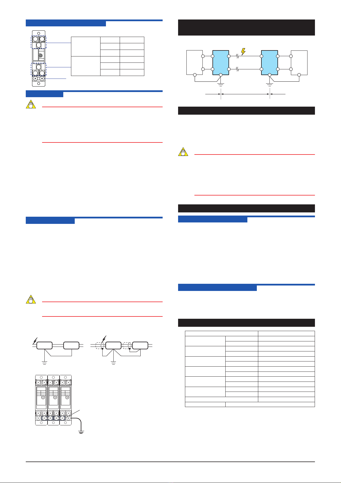
2. CONNECTION OF ARRESTERS WITH
INSTRUMENTS TO BE PROTECTED
Pulse
Generator
Pulse Signal
Convertor
AR-LP AR-LP
A
B
1
2
1
2
A
BGND
Ground Terminal Ground Terminal
Protect side Protect side
Surge side
Lightning
Surge
+
í
3. ENVIRONMENTAL CONDITIONS
Ambient temperature: −10 to +60°C
Relative humidity: 5 to 90% RH (No condensation)
Altitude at installation site: Max. 2000 m above sea level
Installation category based on IEC/EN61010-1: II, pollution
degree: 2 (see Note.)
NOTE
The “Installation Category” implies the regulation for
impulse withstand voltage. It is also called the
“Overvoltage category”.“ II ” applies to electrical
equipment.“Pollution level” describes the degree
to which a solid, liquid or gas which deteriorates
dielectric strength is adhering.“2” applies to a normal
indoor atmosphere.
4. MANTENABCE
4.1 Arrester Checking
The arrester main body and terminal base are connected by plug-
in. Circuit between surge side and protect side would not be open
even if the main body is removed from the socket on terminal
base by loosing main unit-fixing screw. To check the arrester
performance, remove the main body from the socket and check
it by using the AR2-CK (arrester checker: option). If the arrester
cannot be used because the main body is deteriorated or broken,
be sure to replace both the main body and the terminal block.
The terminal block may be damaged by receiving surges. The
replacement of only the main body may fail to meet its protection
performance level.
4.2 Arrester check period
To protect the instrument from damage by induced lightning, the
arrester should be checked periodically at least once a year. In
areas where lightning occurs frequently, check should be done
more often particularly after thunderstorms.
5. HARDWARE SPECIFICATION
Use 2-wire System Pulse Signal
*
Maximum continuous
operating voltage (Uc)
Between lines 50 V DC
Between ground 50 V DC
Permissible current
leakage
Between lines 10 μA or less (at 50 V DC)
Between ground 10 μA or less (at 50 V DC)
Instrument side voltage
limit (10 kV, 1.2/50 μA)
Between lines 90 V or less
Between ground 250 V or less
*Voltage protection
level (Up)
Between lines 350 V or less
Between ground 350 V or less
*Impulse durability
(8/20 μA)
Category C1 500 A
Category C2 5000 A
Discharge starting
voltage
Between lines 74 V DC or more
Between ground 74 V DC or more
*Rated current 2 A DC
JIS compliant JIS C 5381-21 (Category: C1, C2)
*: Description compliant with JIS C 5381-21.

Other YOKOGAWA Industrial Equipment manuals

YOKOGAWA Centum V Installation and operation manual

YOKOGAWA

YOKOGAWA Centum V Installation and operation manual

YOKOGAWA FD20 User manual

YOKOGAWA

YOKOGAWA FD20 User manual

YOKOGAWA ProSafe-RS User manual

YOKOGAWA

YOKOGAWA ProSafe-RS User manual

YOKOGAWA PH8HS User manual

YOKOGAWA

YOKOGAWA PH8HS User manual

YOKOGAWA Green Series User manual

YOKOGAWA

YOKOGAWA Green Series User manual

YOKOGAWA PR20 User manual

YOKOGAWA

YOKOGAWA PR20 User manual

YOKOGAWA SMARTDAC+ User manual

YOKOGAWA

YOKOGAWA SMARTDAC+ User manual

YOKOGAWA ys100 series Parts list manual

YOKOGAWA

YOKOGAWA ys100 series Parts list manual

YOKOGAWA VJHR Series User manual

YOKOGAWA

YOKOGAWA VJHR Series User manual

YOKOGAWA ProSafe-RS User manual

YOKOGAWA

YOKOGAWA ProSafe-RS User manual

YOKOGAWA ISC40PR User manual

YOKOGAWA

YOKOGAWA ISC40PR User manual

YOKOGAWA FF20 User manual

YOKOGAWA

YOKOGAWA FF20 User manual

YOKOGAWA DAQSTATION DX100 User manual

YOKOGAWA

YOKOGAWA DAQSTATION DX100 User manual

YOKOGAWA AE100D User manual

YOKOGAWA

YOKOGAWA AE100D User manual

YOKOGAWA PH8HF User manual

YOKOGAWA

YOKOGAWA PH8HF User manual

Popular Industrial Equipment manuals by other brands

Graphic Whizard Graphic Whizard GW 6000 instruction manual

Graphic Whizard

Graphic Whizard Graphic Whizard GW 6000 instruction manual

Georg Fischer Signet 2630-X instructions

Georg Fischer

Georg Fischer Signet 2630-X instructions

Siemens SIRIUS 3RA233-8X.30-1 Series Original operating instructions

Siemens

Siemens SIRIUS 3RA233-8X.30-1 Series Original operating instructions

ABB HT608838 Operation manual

ABB

ABB HT608838 Operation manual

Rotary RWC1200 Leverless Pro Operation & maintenance manual

Rotary

Rotary RWC1200 Leverless Pro Operation & maintenance manual

Viessmann 8432 Operation manual

Viessmann

Viessmann 8432 Operation manual

Intimus 20000 S operating instructions

Intimus

Intimus 20000 S operating instructions

Tsubaki TKP25H15 instruction manual

Tsubaki

Tsubaki TKP25H15 instruction manual

Huawei BTS3900C installation guide

Huawei

Huawei BTS3900C installation guide

Jäger Z45-D160.05 S3A manual

Jäger

Jäger Z45-D160.05 S3A manual

GARANT SG1 Operation manual

GARANT

GARANT SG1 Operation manual

Zimmer GEH8000 Series Installation and operating instructions

Zimmer

Zimmer GEH8000 Series Installation and operating instructions

Merand MECAFORM VE manual

Merand

Merand MECAFORM VE manual

Sime OPEN HYBRID MEM-ECO 25-6 Installation and maintenance manual

Sime

Sime OPEN HYBRID MEM-ECO 25-6 Installation and maintenance manual

Canon Die Bonder BESTEM-D01 manual

Canon

Canon Die Bonder BESTEM-D01 manual

Siemens SENTRON SUPERSWITCH 3KL84 Series Operating	 instruction

Siemens

Siemens SENTRON SUPERSWITCH 3KL84 Series Operating instruction

APE 100 WICK owner's manual

APE

APE 100 WICK owner's manual

ABB HT584444 Operation manual

ABB

ABB HT584444 Operation manual

manuals.online logo
manuals.online logoBrands
  • About & Mission
  • Contact us
  • Privacy Policy
  • Terms and Conditions

Copyright 2025 Manuals.Online. All Rights Reserved.