YOKOGAWA ISC40PR User manual

IM 12D8K4-E-E
4th edition
Instruction
Manual
Model ISC40PR
Retractable fitting for
Inductive Conductivity sensor

IM 12D8K4-E-E
2
TABLE OF CONTENTS
1. INTRODUCTION ............................................................................................................3
1-1. Description .............................................................................................................3
1-2. Features .................................................................................................................3
1-3. Warranty.................................................................................................................3
2. SPECIFICATIONS ..........................................................................................................4
2-1. General...................................................................................................................4
2-2. Model- and suffix codes .........................................................................................5
2-3. Option codes .........................................................................................................5
2-4. Sensor codes .........................................................................................................5
3. INSTALLATION ..............................................................................................................6
3-1. Unpacking and checking ........................................................................................6
3-2. Installation site........................................................................................................6
3-3. Safety precautions..................................................................................................6
3-4. Installation method .................................................................................................6
3-5. Assembly of accessories ........................................................................................6
3-6. Dimensions.............................................................................................................7
3-7. Dimensions of the options ......................................................................................8
3-8. Installation examples ..............................................................................................9
3-9. Mounting the sensor into the fitting ......................................................................10
3-10. Probe insertion ...................................................................................................11
3-11. Adjusting the insertion depth ..............................................................................13
4. MAINTENANCE ...........................................................................................................14
4-1. General.................................................................................................................14
4-2. Taking out the sensor...........................................................................................14
4-3. Replacing the sensor............................................................................................14
4-4. Drain port connection...........................................................................................14
5. EXPLODED VIEW ........................................................................................................15
5-1. Spare parts list .....................................................................................................16

IM 12D8K4-E-E
3
1. INTRODUCTION
1-1. Description
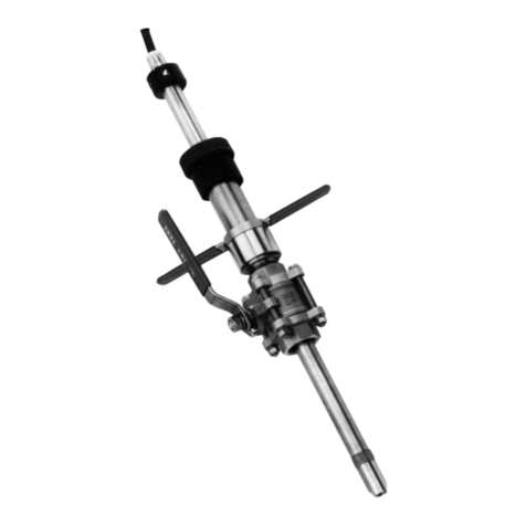
The retractable fitting with ball valve allows
a safe insertion and retraction of a sensor
while the process is under pressure. It can
be mounted in a variety of positions. The
insertion depth can be chosen on site. An
insertion stop is provided to set the
position of the sensor in the process.
The mechanism for releasing the probe is
designed to operate only when the ball
valve is closed, thus ensuring an effective
safety precaution. The sensor can be
replaced or calibrated easily.
1-2. Features
GA safe “through the valve” insertion and
retraction design.
GAdditional safety through a special
designed T-bar locking mechanism.
GMaintenance, replacement and
calibration of the sensor without
interruption of the process.
GAdjustable insertion depth for optimal
measuring position in the process.
GReplacement of the sensor.
GImproved sealing and damping by
additional o-rings.
GSimplified installation by optional ball
valves with flanged or tapered
connections.
GAvailable in 0.5 and 1 metre probe
length in two different materials.
1-3. Warranty
Yokogawa Europe B.V. warrants that the
goods delivered are made from new
materials to the best workmanship
available. Malfunction of any of the
delivered goods or parts of it, can only lead
to replacement of the damaged parts. No
claims can be made to damages or
accidents resulting from the use of the
goods.
No claims can be made to the expected or
promised performance of the goods under
any circumstances.
Damaged goods or parts should be sent to
the local service organisation for warranty
claim purposes.
Yokogawa has the right to deny warranty
claims after investigation of the data and
materials.

IM 12D8K4-E-E
4
2. SPECIFICATIONS
2-1. General
Materials
Wetted parts
Model ISC40PR-S (Stainless steel) Model ISC40PR-T (Titanium)
- Probe Stainless steel AISI 316 Titanium (Grade 2 or 3)
- O-ring seals Viton 70° shore Viton 70° shore
Non-wetted parts
- Stainless steel (AISI 316) and polyphenylene sulphide (PPS)
Insertion length : The proble length can be adjusted to a
maximum of either 0.5 or 1 metre. The actual
probe insertion length depends on the use of
optional adapters and/or ball valves. The
dimensional drawing indicates the maximum
insertion length for both specified probe lengths.
Pressure/temperature ratings
- Static conditions : 2 MPa at 20 °C
: 500 kPa at 130 °C
- Operating conditions maintenance : max. 500 kPa
: max. 130 °C
- Flange ratings : - DIN flange DN50 PN16
- ANSI flange 2” 150 lbs
- JIS flange 16K - 50
Weight : Approx 2.5 kg. (stainless steel version without
ball-valve and adapters)

IM 12D8K4-E-E
5
Model Option code Description
BV40 ............................................................ Titanium Ball Valve 2”
/P ..................................... Rc2 threaded
/Q..................................... 2” NPT threaded
/R..................................... 2” ANSI flanged
/S ..................................... NW 50 flanged
Titanium ball valves are available as separate item
2-2. Model- and suffix codes
2-4. Sensor codes
ISC40왏-PR-왏왏-왏왏
G = General purpose sensor
S = Intrinsically safe sensor
T1 = Pt1000
T3 = Thermistor (only when used with IC200)
Cable length in metres (03, 05, 10, 15 or 20)
Model Suffix Option Description
Code
ISC40PR Retractable Fitting, 2” BSP-female
Material -S Stainless steel AISI 316
-T Titanium Grade 2 or 3
Probe -05 0.5 m
length -10 1.0 m
/A Adapter R2-G2 Stainless steel
/B Adapter 2” NPT-G2 Stainless steel
/C Flange adapter Stainless steel
/D Flange adapter for drain Stainless steel
/E Adapter R2-G2 Titanium Grade 2 or 3
/F Adapter 2” NPT-G2 Titanium Grade 2 or 3
/G Flange adapter Titanium Grade 2 or 3
/H Flange adapter for drain Titanium Grade 2 or 3
/M Material certificate 3.1.B according to EN 10 204
(DIN 50 049) (on wetted parts)
/T Test certificate for hydrostatic pressure test
(2 MPa at ambient temperature)
/J Ball valve R2 Stainless steel
/K Ball valve 2” NPT Stainless steel
/L Ball valve 2” ANSI Flanged Stainless steel
/N Ball valve DN 50 PN16 Flanged Stainless steel

IM 12D8K4-E-E
6
3. INSTALLATION
3-1. Unpacking and checking
When you receive the ISC40PR retractable
fitting it is packed in a cardboard box.
Open the box and check that the model
code on the fitting is the same as the one
on the packing list. See §2-2 for the model
code. Also check that it is supplied with the
options you ordered.
The options can be delivered in separate
boxes. If you have any problems or
questions, contact your nearest Yokogawa
service centre or sales organisation for
support.
The ISC40PR retractable fitting has an
identification plate on the protection ring
with the full model code and a serial
number.
3-2. Installation site
The ISC40PR fitting is intended to be used
for in-line conductivity measurement. When
it is delivered with an optional ball valve or
when it is used in combination with a
locally purchased ball valve, the process
need not be interrupted for maintenance of
the sensor.
The location can be in a large diameter
pipeline or a vessel.
3-3. Safety precautions
The ISC40PR fitting has been designed to
give maximum safety in operation. For
optimum safety a flanged ball-valve is
recommended.
Yokogawa does not accept any claims or
penalties on possible damages or
accidents which occurred by operation of
the ISC40PR fitting.
The installation of the probe is to be
implemented under the local safety
regulations for pressurised vessels or pipe
lines for retraction or insertion.
The instructions given in this manual must
be followed exactly.
3-4. Installation method
It is important to have the point of
measurement in a location that is truly
representing the process composition.
Check whether the specifications of the
sensor fulfil the maximum occurring
process conditions. The fitting has several
optional connection possibilities. Check
that you received the correct size and type.
Install the fitting in a convenient location for
maintenance and calibration. For
maintenance or calibration the probe will
need a space of about 2 metre for total
retraction (depending on probe length and
optional adapters and/or ball valves).
Installation in a bend of a pipe line is a
good measurement position. When
inserting the ISC40PR retractable fitting in
a perpendicular position to the process
flow, the flow velocity will put a mechanical
force on the probe. Take care that this
force is not too large.
Note:
Do not insert the fitting into the process
without the sensor mounted! The sensor
is delivered separately in a box.
Start with the assembly of the sensor into
the probe and follow the instructions for
the preparation of a new sensor. See §3-8.
3-5. Assembly of accessories
Optional accessories are (mostly) delivered
separately in boxes.
When a ball valve is ordered as an option,
this should be mounted to the measuring
position first. When the ball valve is in
place, the process line is secure.
If the ball valve has a tapered connection, it
needs to be locked with glue.
Next the adapter at the other side of the
ball valve needs to be mounted. This
adapter has ISO 228/1-G2 male thread at
one side and a matching connection for the
ball valve at the other side. Mount the
adapter on the ball valve and lock it with
glue.
IM 12D8K4-E-E
7
3-6. Dimensions
500 or 1000 (19.70 or 39.37)
282 (11.10)
max. 345 or 845 (13.58 or 33.26)
ISO 228/1-G2
140 (5.51)
min.150 (5.9)
max.130 (5.11)
max.
160 or 660
(6.29 or 25.98)
min. 150 (5.9)
(NW50 (150mm or 5.9")
(2" ANSI (180mm or 7.08")
max. (NW50)
120mm or 620
(4.72 or 24.4)
max.130 (5.11)
(2") 90mm or 590
(3.54 or 23.22)
Note: Bolt, nuts and gaskets are not included.

IM 12D8K4-E-E
8
3-7. Dimensions of the options
Options /C, /G
ISO 228/1-G2
54 (2.12")
UNIVERSAL FLANGE
DIN Flange DN50 PN16
ANSI Flange 2" 150 lbs
JIS Flange 2" 150 lbs
Options /A, /B, /E, /F
ISO 228/1-G2
ISO 7/1-R2
or
2 -11.5 NPT
Options /D, /H
ISO 228/1-G2
77 (3")
1/8-27 NPT
UNIVERSAL FLANGE
DIN Flange DN50 PN16
ANSI Flange 2" 150 lbs
JIS Flange 2" 150 lbs

3-8. Installation examples
IM 12D8K4-E-E
9

IM 12D8K4-E-E
10
3-9. Mounting the sensor into the
fitting
1. Take the sensor out of the box and
remove the cable tie carefully.
2. Bind the separate wires of the cable
together with a piece of tape.
3. Take the fitting out of the box and
remove the option(s), if necessary.
4. Screw the knurled knob out off the
fitting
5. Release the pigtail (cable gland)
completely. Do not undo the part in the
metal tube!
6. Lead the sensor cable through the
tube of the fitting, from the side where
the knurled knob has been removed.
5
4
12D8K4-07
SCREWING INTO TUBE
6. Hold the sensor still and turn the metal
tube onto the sensor.
Don’t rotate the cell, but rotate the
tube of the fitting, because the cable
can be disconnected from the cell,
when rotating it.
7. Lead the loose part of the pigtail onto
the cable and screw it onto the fixed
part.
8. Remove the tape.
9. Retain the knurled knob for future use
or discard.
It is not necessary while the fitting is
installed.

IM 12D8K4-E-E
11
3-10 Probe insertion
1. Position the probe for insertion.
2. Turn the T-bar key clockwise.
3. Open the ball valve.
4. Push the probe into the process.
5. Fix the probe by turning the fixing
screw clockwise.
Remarks:
- Turning the T-bar key can only be done
when the valve is closed.
FIXING SCREW
1
- Pushing the probe into the process needs
a force to overcome the pressure of the
system and the friction of the dampening
rings in the fitting.
- The locking mechanism can be tightened
until the probe is firmly fixed at the
measuring position.
- The insertion stop can be fixed at the
actual insertion position. See §3-10 on
adjusting the insertion depth.
2

IM 12D8K4-E-E
12
4
3
5

IM 12D8K4-E-E
13
3-11. Adjusting the insertion depth
The insertion depth of the sensor can be
adjusted to your preference.
The insertion stop can be set for at the
actual insertion position of the probe. The
“Allan” key, supplied with the fitting, is used
to fix the insertion stop at the desired
position.
The maximum insertion depth is related to
the probe length mentioned in the model
code of the fitting.

IM 12D8K4-E-E
14
4. MAINTENANCE
4-1. General
Before the sensor can be serviced, the
probe with the sensor inside should be
physically separated from the process.
The ISC40PR retractable fitting can be
retracted from its measuring position in the
maintenance position by following the five
step procedure mentioned in §3-9 in
reverse order.
4-2. Taking out the sensor
Retract the probe from the process
according to the following procedure:
1. Release the fixing screw.
2. Pull out the probe.
3. Close the ball valve (*).
4. Turn the T-bar counter clockwise
5. Take out the probe.
* : If the option drain port is available, the
process pressure can be relieved before
removing the sensor.
Remarks:
- Stand clear when releasing the fixing
screw! Due to the process pressure the
probe can be pressed out.
- The T-bar key can only be operated when
the ball valve is closed. Make sure it is
closed completely.
- The friction of the o-rings will slow down
the probe when it is retracted.
4-3. Replacing the sensor
Refer to §3-8.
4-4. Drain port connection
The ISC40PR retractable fitting can be
equipped with optional drain port on the
flanged adapter.
The drain port are tapered 1/8” NPT female
for small diameter connectors.
Drain port connection

IM 12D8K4-E-E
15
5. EXPLODED VIEW
18
19
17
10 12
13
14
15 16
123
4
5
6
7
6
99
88
11
20
12D8K4-01
INDUCTIVE RETRACTABLE
FITTING EXPLO ISC 40 PR
No. Description Part No.
1 Cable gland K1500BH
2 Outer tube 0,5 m SS K1520TN
2 Outer tube 1 m SS K1520UH
2 Outer tube 0,5 m Ti K1520UF
2 Outer tube 1 m Ti K1520UJ
3 Insertion stop K1520KF
4 “Allan” screw K1520KC
5 Main fixing screw K1520KC
6 Squeezing ring (2 pcs.) SS K1520TA
6 Squeezing ring (2 pcs.) Ti K1520UB
7 Clamping ring SS K1520TA
7 Clamping rin Ti K1520UB
8 O-rings (2 pcs.) 20,2x3,5 Viton K1500BG
8 O-rings (2 pcs.) 20,2x3,5 EPDM K1500EA
8 O-rings (2 pcs.) 20,2x3,5 Kalrez K1500EB
9 Bushing (2 pcs.) SS K1520TA
9 Bushing (2 pcs.) Ti K1520UB
10 Protection ring
11 Fixing screws (2 pcs.)
12 T-bar with key K1520TK
13 Nut K1520DD
14 Fixing screws (2 pcs.)
15 Chamber
16 1x Kalrez 70° shore 47,2x3,5 K1500EC
17 Adapter (optional)
18 Ball valve (optional)
19 Sensor
20 2 pcs. Kalrez 70° shore 15,6x1,78 K1500ED
20 10 pcs. Viton 70° shore 15,6x1,78 K1500BE
Description Part No.
O-ring Kalrez 29,74x3,53 K1500AH
O-ring set EPDM, ISC40 PR K1500EA
Sensor holder SS (ISC40PR) K1500EN
Sensor holder Ti (ISC40PR) K1500EP
Outer tube 0,5m SS, ISC40PR K1520UK
Outer tube 1,0m SS, ISC40PR K1520UL
Outer tube 0,5m Ti, ISC40PR K1520UM
Outer tube 1,0m Ti, ISC40PR K1520UN
Ball valve R2 (ISC40PR/J) K1541DQ
Flange adapter SS (ISC40PR/C) K1541DR
Flange adapter SS-drain ISC40PR/D K1541DS
Flange adapter Ti (ISC40PR/G) K1541DT
Flange adapter Ti-drain (ISC40PR/H) K1541DU
Ball valve 2” NPT (ISC40PR/K) K1541DW
Ball valve 2” ANSI (ISC40PR/L) K1541DX
Ball valve DN50 PN16 (ISC40PR/N) K1541DY
Adapter R2-G2-SS (ISC40PR/A) K1541EJ
Adapter 2” NPT-G2-SS (ISC40PR/B) K1541EM
Adapter R2-G2-Ti (ISC40PR/E) K1541EN
Adapter 2” NPT-G2-Ti (ISC40PR/F) K1541EP

IM 12D8K4-E-E Copyright © 04-508 (A) Q
Subject to change without notice Printed in The Netherlands
YOKOGAWA EUROPE B.V.
Databankweg 20
3821 AL AMERSFOORT
The Netherlands
Tel. +31-33-4641 611
Fax +31-33-4641 610
E-mail: [email protected]
www.yokogawa.com/eu
YOKOGAWA CORPORATION OF AMERICA
2 Dart Road
Newnan GA 30265
United States
Tel. (1)-770-253-7000
Fax (1)-770-251-2088
E-mail: [email protected]
www.yokogawa.com/us
YOKOGAWA ELECTRIC ASIA Pte. Ltd.
5 Bedok South Road
Singapore 469270
Singapore
Tel. (65)-241-9933
Fax (65)-241-2606
E-mail: [email protected]
www.yokogawa.com.sg
YOKOGAWA HEADQUARTERS
9-32, Nakacho 2-chome,
Musashinoshi
Tokyo 180
Japan
Tel. (81)-422-52-5535
Fax (81)-422-55-1202
E-mail: [email protected]
www.yokogawa.com
Yokogawa has an
extensive sales and
distribution network.
Please refer to the
European website
(www.yokogawa.com/eu)
to contact your nearest
representative.
Table of contents
Other YOKOGAWA Industrial Equipment manuals

YOKOGAWA
YOKOGAWA SMARTDAC+ User manual

YOKOGAWA
YOKOGAWA ProSafe-RS User manual

YOKOGAWA
YOKOGAWA AE100D User manual

YOKOGAWA
YOKOGAWA Green Series User manual

YOKOGAWA
YOKOGAWA VJHR Series User manual

YOKOGAWA
YOKOGAWA ProSafe-RS User manual

YOKOGAWA
YOKOGAWA FD20 User manual

YOKOGAWA
YOKOGAWA PH8HS User manual

YOKOGAWA
YOKOGAWA FF20 User manual

YOKOGAWA
YOKOGAWA PR20 User manual
Popular Industrial Equipment manuals by other brands

Dover
Dover DESTACO TC1 Series Service manual

Baileigh
Baileigh SR-5016M Operator's manual

TigerStop
TigerStop TigerFence user manual

Spartan
Spartan 87301 installation instructions

DRIESCHER-WEGBERG
DRIESCHER-WEGBERG MINEX-C ABS zero Operation and assembly instructions

Kärcher
Kärcher NT 65/2 Tact2 Original instructions