YOKOGAWA DL850E User manual

IM DL850E-01EN
1st Edition
ScopeCorder
DL850E/DL850EV
Features Guide

i
IM DL850E-01EN
Thank you for purchasing the DL850E ScopeCorder or DL850EV ScopeCorder Vehicle Edition (hereinafter,
“DL850E/DL850EV” will refer to both of these products). This manual contains useful information about the
features of the DL850E/DL850EV. To ensure correct use, please read this manual thoroughly before beginning
operation.
Keep this manual in a safe place for quick reference in the event a question arises. The following five manuals,
including this one, are provided as manuals for the DL850E/DL850EV. Read them along with this manual.
Manual Title Manual No. Description
DL850E/DL850EV ScopeCorder
Features Guide
IM DL850E-01EN This manual. The supplied CD contains the PDF file of this
manual. This manual explains all the DL850E/DL850EV features
other than the communication interface features.
DL850E/DL850EV ScopeCorder
User’s Manual
IM DL850E-02EN The supplied CD contains the PDF file of this manual. The manual
explains how to operate the DL850E/DL850EV.
DL850E/DL850EV ScopeCorder
Getting Started Guide
IM DL850E-03EN The manual explains the handling precautions and basic
operations of the DL850E/DL850EV and provides an overview of
its features.
DL850E/DL850EV ScopeCorder
Communication Interface
User’s Manual
IM DL850E-17EN The supplied CD contains the PDF file of this manual.The manual
explains the DL850E/DL850EV communication interface features
and instructions on how to use them.
DL850E/DL850EV ScopeCorder
Real Time Math (/G3 Option)
User’s Manual
IM DL850E-51EN The supplied CD contains the PDF file of this manual.This manual
explains the features of the DL850E/DL850EV Real Time Math
option and how to use it.
Notes
• The contents of this manual are subject to change without prior notice as a result of continuing improvements
to the instrument’s performance and functions. The figures given in this manual may differ from the actual
screen.
•Every effort has been made in the preparation of this manual to ensure the accuracy of its contents. However,
should you have any questions or find any errors, please contact your nearest YOKOGAWA dealer.
•Copying or reproducing all or any part of the contents of this manual without the permission of YOKOGAWA is
strictly prohibited.
•The TCP/IP software of this product and the documents concerning it have been developed/created by
YOKOGAWA based on the BSD Networking Software, Release 1 that has been licensed from the Regents of
the University of California.
Trademarks
• Microsoft, Internet Explorer, MS-DOS, Windows, Windows NT, Windows XP, and Windows Vista are either
registered trademarks or trademarks of Microsoft Corporation in the United States and/or other countries.
• Adobe, Acrobat, and PostScript are either registered trademarks or trademarks of Adobe Systems
Incorporated.
•GIGAZoom ENGINE is a registered trademark of Yokogawa Electric Corporation.
• MATLAB is a registered trademark of The MathWorks, Inc. in the United States.
• In this manual, the ® and TM symbols do not accompany their respective registered trademark or trademark
names.
• Other company and product names are registered trademarks or trademarks of their respective holders.
Revisions
• 1st Edition: December 2013June 2010
1st Edition: December 2013 (YMI)
All Rights Reserved, Copyright © 2013 Yokogawa Meters & Instruments Corporation

ii IM DL850E-01EN
Contents
1 Main Features
Vertical Axis................................................................................................................................... 1-1
Horizontal Axis (Time Axis) ........................................................................................................... 1-2
Trigger........................................................................................................................................... 1-3
Waveform Acquisition ................................................................................................................... 1-4
Waveform Display......................................................................................................................... 1-6
Waveform Computation and Analysis ........................................................................................... 1-6
Notes about Using the 16-CH Voltage Input Module (720220),
Notes about Using the 16-CH
Temperature/Voltage Input Module (720221) .............................................................................................1-8
2 Vertical Axis
Input Settings................................................................................................................................ 2-1
Voltage Measurement................................................................................................................... 2-2
Vertical Scale (SCALE knob) ........................................................................................................ 2-3
Waveform Vertical Position (Vertical POSITION knob)................................................................. 2-5
Input Coupling (Coupling) ............................................................................................................. 2-6
Probe Attenuation and Current-to-Voltage Conversion Ratio (Probe) .......................................... 2-7
Bandwidth (Bandwidth)................................................................................................................. 2-8
Zoom Method (V Scale)................................................................................................................ 2-9
Offset (Offset) ..............................................................................................................................2-11
DC Offset Cancel (DC Offset Cancel)......................................................................................... 2-12
Gain Adjustment (Gain)............................................................................................................... 2-12
Inverted Waveform Display (Invert) ............................................................................................ 2-13
Linear Scaling (Linear Scale)...................................................................................................... 2-14
RMS Measurement..................................................................................................................... 2-16
Voltage Measurement (For the 16-CH Voltage Input Module).................................................... 2-17
Temperature Measurement......................................................................................................... 2-20
Temperature Measurement (For the 16-CH Temperature/Voltage Input Module)....................... 2-22
Strain Measurement.................................................................................................................... 2-24
About Shunt Calibration (Only on the 701271(STRAIN_DSUB))................................................ 2-27
Acceleration Measurement ......................................................................................................... 2-29
Frequency Measurement............................................................................................................ 2-31
FV Setting (F/V Setup) - frequency measurement...................................................................... 2-31
Input Setup (Input Setup) - frequency measurement.................................................................. 2-36
Logic Measurement .................................................................................................................... 2-39
CAN Bus Signal Monitoring (Applies to the DL850EV)............................................................... 2-41
LIN Bus Signal Monitoring (Applies to the DL850EV)................................................................. 2-47
Displaying the Menu for Configuring All Channels (ALL CH)...................................................... 2-51
Digital Filter and Real Time Math (Optional) ............................................................................... 2-53
Digital Filter and Delay (Filter/Delay Setup)................................................................................ 2-53
Real Time Math (RealTime Math) ............................................................................................... 2-56
Arithmetic (S1+S2, S1−S2, S1*S2, and S1/S2) ...................................................................... 2-59
Arithmetic (A(S1)+B(S2)+C, A(S1)−B(S2)+C, A(S1)*B(S2)+C, A(S1)/B(S2)+C)..................... 2-59
Differentiation (Diff(S1))........................................................................................................... 2-59
Integration (Integ1(S1) and Integ2(S1))................................................................................... 2-60
Angle of Rotation (Rotary Angle) ............................................................................................. 2-60
Logic Signal to Analog Waveform Conversion (DA) ................................................................ 2-62
Quartic Polynomial (Polynomial) ............................................................................................. 2-63

iii
IM DL850E-01EN
Contents
RMS Value (RMS) ................................................................................................................... 2-63
Effective Power (Power).......................................................................................................... 2-64
Effective Power Integration (Power Integ)............................................................................... 2-64
Common Logarithm (Log1 and Log2)...................................................................................... 2-65
Square Root (Sqrt1 and Sqrt2)................................................................................................ 2-65
Cosine (Cos) and Sine (Sin).................................................................................................... 2-65
Arc Tangent (Atan)................................................................................................................... 2-66
Electrical Angle (Electrical Angle)............................................................................................ 2-66
Knocking Filter (Knock Filter; only on the DL850EV) .............................................................. 2-67
Polynomial with a coefficient (Poly-Add-Sub).......................................................................... 2-67
Frequency (Frequency) ........................................................................................................... 2-68
Period (Period) ........................................................................................................................ 2-68
Edge Count (Edge Count) ....................................................................................................... 2-69
Resolver (Resolver)................................................................................................................. 2-69
IIR Filter (IIR Filter).................................................................................................................. 2-70
Demodulation of the Pulse Width Modulated Signal (PWM) ................................................... 2-71
Reactive Power (Reactive Power(Q))...................................................................................... 2-71
CAN ID Detection (CAN ID)..................................................................................................... 2-72
Torque (Torque) ....................................................................................................................... 2-73
Notes Regarding Using the Digital Filter and Real Time Math ................................................ 2-74
3 Horizontal Axis
Time Axis Setting (TIME/DIV) ....................................................................................................... 3-1
4 Triggering
Trigger Mode (MODE) .................................................................................................................. 4-1
Trigger Types (Type)..................................................................................................................... 4-2
Signal Type and Trigger Type Combinations ................................................................................ 4-2
Basic Trigger Settings ................................................................................................................... 4-2
Simple Trigger (Simple) ................................................................................................................ 4-3
Trigger Source (Source) ............................................................................................................... 4-3
Trigger Level (Level) ..................................................................................................................... 4-4
Trigger Slope (Slope).................................................................................................................... 4-5
Trigger Hysteresis (Hysteresis)..................................................................................................... 4-5
Trigger Hold-Off (Hold Off)............................................................................................................ 4-5
Trigger Position (Position)............................................................................................................. 4-6
Trigger Delay (Delay).................................................................................................................... 4-7
A -> B(N) Trigger (Enhanced) ....................................................................................................... 4-8
A Delay B Trigger (Enhanced) ...................................................................................................... 4-9
Edge On A Trigger (Enhanced)................................................................................................... 4-10
OR Trigger (Enhanced)................................................................................................................4-11
AND Trigger (Enhanced)............................................................................................................. 4-12
Period Trigger (Enhanced).......................................................................................................... 4-13
Pulse Width Trigger (Enhanced) ................................................................................................. 4-14
Wave Window Trigger (Enhanced) ............................................................................................. 4-15

iv IM DL850E-01EN
Contents
5 Waveform Acquisition
Record Length (Record Length) ................................................................................................... 5-1
Acquisition Mode (Acquisition Mode)............................................................................................ 5-2
Hard Disk Recording (HD RecordCondition; optional).................................................................. 5-4
Time Base (Time Base) ................................................................................................................ 5-5
Dual Capture (DUAL CAPTURE).................................................................................................. 5-7
Captured-Waveform Display Number (Select Number)................................................................ 5-8
Waveform Acquisition (START/STOP)........................................................................................ 5-10
6 Display
Window Types (DISPLAY) ............................................................................................................ 6-1
Display Format (Format)............................................................................................................... 6-2
Extra Window (Extra Window) ...................................................................................................... 6-2
Grid (Graticule) ............................................................................................................................. 6-2
Turning the Scale Value Display On and Off (Scale Value) .......................................................... 6-3
Waveform Arrangement, Color, and Display Gr. (Trace Setup) .................................................... 6-3
Trace Label Display (Trace Label)................................................................................................ 6-4
Level Indicator............................................................................................................................... 6-4
Interpolation Method (Dot Connect).............................................................................................. 6-4
Setting the Number of Data Points to Use for Waveform Display (Decimation) ........................... 6-5
Accumulation (Accumulate) .......................................................................................................... 6-5
Manual Event (Manual Event)....................................................................................................... 6-6
Switching the Menu Area Display ................................................................................................. 6-6
7 Displaying X-Y Waveforms
Turning the X-Y Window Display On and Off (Display)................................................................. 7-1
Eight Pairs of X-Y Waveforms (Setup).......................................................................................... 7-1
Start Point and End Point (Start Point and End Point).................................................................. 7-1
Pen Marker (Pen Marker) ............................................................................................................. 7-2
Clearing Waveforms at Acquisition Start (Trace clear on Start).................................................... 7-2
Display Ratio of the Main Window (Main Ratio)............................................................................ 7-2
Window Layout (Window Layout) ................................................................................................. 7-2
Combine Display (Combine Display) ............................................................................................ 7-2
Interpolation Method (Dot Connect).............................................................................................. 7-2
Setting the Number of Data Points to Use for Waveform Display (Decimation) ........................... 7-2
8 Zooming in on Waveforms
Zoom Window Display (Display)................................................................................................... 8-1
Zoom Source Window (Zoom2 Source)........................................................................................ 8-1
Zoom Factor (MAG knob) ............................................................................................................. 8-2
Position (Zoom POSITION knob, Zoom1 Position, Zoom2 Position)............................................ 8-2
Display Ratio of the Main Window (Main Ratio)............................................................................ 8-2
Window Layout (Window Layout) ................................................................................................. 8-2
Display Format (Format Zoom1 and Format Zoom2) ................................................................... 8-3
Moving the Zoom Position to the Latest Position
(Move Zoom1 to Front and Move Zoom2 to Front)....................................................................... 8-3
Auto Scroll (Auto Scroll)................................................................................................................ 8-3
Waveforms That Are Zoomed (Allocation) .................................................................................... 8-3
Changing the Range of the Automated Measurement of Waveform Parameters (Fit Measure
Range) .......................................................................................................................................... 8-3

v
IM DL850E-01EN
Contents
9 Cursor Measurement
Window Selection (Select Window) .............................................................................................. 9-1
T-Y Waveforms ............................................................................................................................. 9-1
Horizontal Cursors (Horizontal) - T-Y waveforms ......................................................................... 9-1
Vertical Cursors (Vertical) - T-Y waveforms .................................................................................. 9-2
Horizontal and Vertical Cursors (H & V) - T-Y waveforms ............................................................ 9-4
Marker Cursors (Marker) - T-Y waveforms ................................................................................... 9-4
Angle Cursors (Degree) - T-Y waveforms..................................................................................... 9-6
X-Y Waveforms............................................................................................................................. 9-7
FFT Waveforms ............................................................................................................................ 9-9
Notes about Cursor Measurement...............................................................................................9-11
10 Automated Measurement of Waveform Parameters
Mode Settings (Mode)................................................................................................................. 10-1
Automated Measurement of Waveform Parameters (ON).......................................................... 10-1
Measurement Items (Measure Setup) ........................................................................................ 10-1
Setting the Delay (Delay Setup).................................................................................................. 10-4
Measurement Time Period (Time Range1/Time Range2) .......................................................... 10-5
1-Cycle Mode (1-Cycle Mode) .................................................................................................... 10-6
Notes about Automated Measurement of Waveform Parameters .............................................. 10-6
Normal Statistical Processing (Statistics) ................................................................................... 10-7
Cyclic Statistical Processing (Cycle Statistics) ........................................................................... 10-8
Statistical Processing of History Waveforms (History Statistics) .............................................. 10-10
Notes about Statistical Processing ............................................................................................10-11
11 Computation
Turning Computation On and Off (Mode).....................................................................................11-1
Computation Waveform Selection (Select Math Trace) ...............................................................11-1
Computation Settings (Math Setup).............................................................................................11-1
Scaling Mode (Scaling Mode)......................................................................................................11-4
Upper and Lower Limits (Upper/Lower).......................................................................................11-4
Start Point and End Point (Start Point/End Point)........................................................................11-4
User-Defined Computation (Optional)..........................................................................................11-4
Expression (Expression) - user-defined.......................................................................................11-4
Averaging Settings (Average Setup) - user-defined ....................................................................11-7
FFT Settings (FFT Setup) - user-defined.....................................................................................11-9
Filter Settings (Filter Setup) - user-defined..................................................................................11-9
Constant Settings (Constant Setup) - user-defined ...................................................................11-10
Notes about Computation ..........................................................................................................11-10
12 FFT
Turning the FFT On and Off (Display)......................................................................................... 12-1
Analysis Source Waveform (Source) .......................................................................................... 12-1
Start Point and Number of FFT Points (Start Point and FFT Points) .......................................... 12-1
Window Function (Window) ........................................................................................................ 12-2
Vertical Scale (Vert. Scale Mode) ............................................................................................... 12-2
Center/Scale (Center/Sensitive) ................................................................................................. 12-2
Display Ratio of the Main Window (Main Ratio).......................................................................... 12-3
Window Layout (Window Layout) ............................................................................................... 12-3
Horizontal Scale (Horiz. Axis) ..................................................................................................... 12-3
Unit (Unit).................................................................................................................................... 12-3
Horizontal Zoom (Horiz. Scale)................................................................................................... 12-3

vi IM DL850E-01EN
Contents
Horizontal Range (Left/Right, Center/Span) ............................................................................... 12-3
FFT Analysis with User-Defined Computation (Optional) ........................................................... 12-4
Notes about FFT Computation.................................................................................................... 12-6
13 GO/NO-GO Determination
Mode (Mode)............................................................................................................................... 13-1
Waveform Zone (Wave Zone)..................................................................................................... 13-1
Waveform Parameters (Parameter)............................................................................................ 13-4
Notes about GO/NO-GO Determination ..................................................................................... 13-5
14 Action
Mode (Mode)............................................................................................................................... 14-1
Action (Action Setup) .................................................................................................................. 14-1
Notes about Action...................................................................................................................... 14-2
15 Searching Waveforms
Search Type (Type)..................................................................................................................... 15-1
Edge Search (Edge) ................................................................................................................... 15-2
Event Search (Event).................................................................................................................. 15-4
Logic Pattern Search (Logic Pattern).......................................................................................... 15-4
Time Search (Time) .................................................................................................................... 15-5
Notes about Searching Waveforms ............................................................................................ 15-5
16 Displaying and Searching History Waveforms
Display Mode (Display Mode)..................................................................................................... 16-2
Highlighting (Selected Record) ................................................................................................... 16-2
Display Range (Start and End Record)....................................................................................... 16-3
List of History Waveforms (List) .................................................................................................. 16-3
History Waveform Search Mode (Search Mode) ........................................................................ 16-4
Search Condition Settings for Zone Searching (Search Setup) ................................................. 16-4
Search Condition Settings for Waveform Parameter Searching (Search Setup)........................ 16-5
Search Execution (Execute Search)........................................................................................... 16-5
Notes about Using the History Feature....................................................................................... 16-5
17 Power Math
Display Group (Digital Monitor Mode)......................................................................................... 17-1
Power Analysis (Power).............................................................................................................. 17-1
Harmonic Analysis (Harmonics)................................................................................................ 17-10
Harmonic Analysis Window Setup (Harmonic Window Setup) ................................................. 17-12
18 Printing and Saving Screen Captures
Destination Type (Print To).......................................................................................................... 18-1
Printing from the Built-In Printer (BuiltIn; option)......................................................................... 18-1
Printing from a Network Printer (Network) .................................................................................. 18-1
Printing on a USB Printer (USB)................................................................................................. 18-2
Saving Screen Captures to Files (File) ....................................................................................... 18-3
Printing or Saving a Screen Capture (PRINT) ............................................................................ 18-3

vii
IM DL850E-01EN
Contents
19 Saving and Loading Data
Storage Media You Can Save and Load From ........................................................................... 19-1
Saving Data (Save)..................................................................................................................... 19-2
Loading Data (Load) ................................................................................................................... 19-7
File Operations (Utility) ............................................................................................................... 19-8
20 Ethernet Communication (Network)
TCP/IP (TCP/IP) ......................................................................................................................... 20-2
FTP Server (FTP/Web Server) ................................................................................................... 20-3
Web Server (FTP/Web Server)................................................................................................... 20-4
Mail (Mail) ................................................................................................................................... 20-5
Network Printer (Net Print).......................................................................................................... 20-6
Network Drive (Net Drive)........................................................................................................... 20-6
SNTP (SNTP) ............................................................................................................................. 20-7
21 Other Features
Auto Setup (Auto Setup)............................................................................................................. 21-1
Initializing Settings (Initialize)...................................................................................................... 21-1
Storing and Recalling Setup Data (Setup Data Store and Recall).............................................. 21-2
Calibration (CAL) ........................................................................................................................ 21-2
Power Integration Calibration (On Models with the /G5 Option)................................................. 21-2
Snapshot (SNAPSHOT).............................................................................................................. 21-2
Clear Trace (CLEAR TRACE)..................................................................................................... 21-3
Remote Control (Remote Ctrl) .................................................................................................... 21-3
System Configuration (System Configuration)............................................................................ 21-4
Environment Settings (Preference)............................................................................................. 21-7
Self-Test (Selftest)..................................................................................................................... 21-10
Overview (Overview)..................................................................................................................21-11
Key Lock (KEY PROTECT) .......................................................................................................21-11
NUM LOCK................................................................................................................................21-11
Appendix
Appendix 1 How to Calculate the Area of a Waveform...........................................................App-1
Appendix 2 User-Defined Computation (Optional) ................................................................. App-3
FFT Function - user-defined ..................................................................................................... App-7
Appendix 3 Fundamental Equations for Defining Strain....................................................... App-13
Appendix 4 Shunt Calibration of the Strain Module.............................................................. App-14
Shunt Calibration Procedure................................................................................................... App-15
Appendix 5 Measurement Principle of the Frequency Module.............................................App-19
Appendix 6 List of Preset Settings of the Frequency Module............................................... App-23
Appendix 7 TCP and UDP Port Numbers.............................................................................App-26
Appendix 8 Using Data Files (WDF Files)............................................................................App-26
Index

1-1
IM DL850E-01EN
1 Main Features
Vertical Axis
This section explains how to configure the signal input settings and the amplitude-direction display settings. The
items that can be set vary depending on the installed modules. The channel menu that corresponds to the key
you pressed (CH1 to CH16) appears. You can set the various vertical axis settings for each channel. Press ALL
CH to display a screen in which you can configure the settings of all channels while viewing the settings in a list.
DL850E/DL850EV Measurement Items
When the DL850E/DL850EV is equipped with the modules listed below, it can measure voltage, temperature,
strain, acceleration, frequency, logic, CAN bus signals, LIN bus signals, and so on.
Voltage
701250 (HS10M12), 701251 (HS1M16), 701255 (NONISO_10M12), 701267 (HV (with RMS)), 720210
(HS100M12), 701261 (UNIVERSAL), 701262 (UNIVERSAL (AAF)), 701265 (TEMP/HPV), 701275 (ACCL/VOLT)
Voltage (For the 16-CH Voltage Input Module)
720220 (16CH VOLT)
Temperature
701261 (UNIVERSAL), 701262 (UNIVERSAL (AAF)), 701265 (TEMP/HPV)
Temperature (For the 16-CH Temperature/Voltage Input Module)
720221 (16CH TEMP/VOLT)
Strain
701270 (STRAIN_NDIS), 701271 (STRAIN_DSUB)
Acceleration
701275 (ACCL/VOLT)
Frequency
701280 (FREQ)
Logic
720230 (LOGIC)
CAN Bus Signal Monitoring
720240(CAN MONITOR), 720241 (CAN & LIN)
These modules can be used only with the DL850EV.
LIN Bus Signal Monitoring
720241 (CAN & LIN)
This module can be used only with the DL850EV.
Digital Filter and Real Time Math (Optional)
Vertical Scale
The vertical scale is used to adjust the displayed waveform amplitude so that you can easily view signals. You
can set the vertical scale to determine the value per grid square (1 div) displayed on the screen and to set the
measurement range.
Use the SCALE knob to set the vertical scale for each channel.
Vertical Position
Because the DL850E/DL850EV can display many waveforms, the waveforms may overlap and be difficult to
view. If this happens, you can adjust the vertical display position to make waveforms easier to view (vertical
position).
Use the POSITION knob to set the vertical position for each channel.

1-2 IM DL850E-01EN
Input Coupling
You can change the input coupling setting to match the signal that you are measuring. By changing the setting,
you can choose how the vertical-axis (voltage-axis) control circuit is coupled to the input signal. The following
types of input coupling are available: DC, AC, GND, TC, DC-RMS, AC-RMS, ACCEL, and OFF.*Set the
appropriate input coupling for each input module.
* If you do not want to measure the selected sub channels on a 16-CH voltage input module or a 16-CH
temperature/voltage input module, set them to OFF.
Vertical Zoom
You can zoom the waveform vertically. You can zoom the waveform by setting the vertical magnification or by
setting upper and lower display limits.
Linear Scaling
Linear scaling is a function that converts measured values into physical values and reads them directly. There
two types of linear scaling:
AX+B
Using scaling coefficient A and offset B, the DL850E/DL850EV scales values according to the equation below.
Y= AX + B (where X is the measured value and Y is the physical value)
P1-P2
The DL850E/DL850EV determines the scale conversion equation (y = ax + b) using four values that you specify:
two measured values (P1:X, P2:X) and the value that each one should be converted to (P1:Y
, P2:Y).
The DL850E/DL850EV scales values using the scale conversion equation that it determines.
Measurement range
P1
P2
P1:X P2:X
P1:Y
P2:Y
y = ax + b
Measured values
Physical values (scaled values)
Horizontal Axis (Time Axis)
Time Axis Setting
Normally, under the initial settings, the time axis scale is set as a length of time per grid division (1 div). The
selectable range is 100 ns/div to 20 days/div.*As you adjust the value, the unit changes between seconds,
minutes, hours, and days automatically. Because the horizontal display range is 10 div, the amount of time on
the waveform that is displayed is equal to the time axis setting × 10.
* When the 720210 (HS100M12) module is installed, the scale range starts at 100 ns/div; when it is not
installed, the scale range starts at 1 μs/div.
Internal and External Clocks (Time base selection)
Under the initial settings, the DL850E/DL850EV samples the measured signal using the internal clock signal
produced by its internal time-base circuit.
You can also use an external clock signal to control sampling. Apply the external clock signal to the external-
clock input terminal. This external clock input is useful for synchronizing to the clock signal of the waveform that
is being measured.
1 Main Features

1-3
IM DL850E-01EN
Relationship between the Time Axis Setting, Record Length, and Sample Rate
If you change the time axis setting, the sample rate and the acquisition-memory record length also change. For
details, see appendix 1 in the Getting Started Guide, IM DL850E-03EN.
Sample Rate
If you change the time axis setting, the sample rate also changes. The sample rate is the number of samples-
per-second (S/s). When the sample rate is low compared to the frequency of the input signal, the high-frequency
components of the waveform are misread as low-frequency components. To prevent the high-frequency
components from being misread, sample the signal at the highest sample rate possible, or set the waveform
acquisition mode to Envelope.
Roll Mode Display
When the trigger mode is set to Auto, Auto Level, Single, or On Start and the time axis setting is greater than or
equal to 100 ms/div, instead of updating waveforms through triggering (update mode), the DL850E/DL850EV
displays the waveforms in roll mode. In roll mode, waveforms scroll from right to left as new data is captured and
the oldest values are deleted from the screen.
Trigger
A trigger is a cue used to display the waveform on the screen. A trigger occurs when the specified trigger
condition is met, and a waveform is displayed on the screen.
Trigger Modes
The trigger mode determines the conditions for updating the displayed waveforms. There are six trigger modes:
Auto, Auto Level, Normal, Single, N Single, and On Start. The trigger mode setting applies to all trigger types.
Trigger Types
Triggers can be broadly divided into “simple triggers” and “enhanced triggers.”
Simple Triggers
Input Signal Trigger
The DL850E/DL850EV triggers when the trigger source passes through the specified trigger level in the specified
way (rising edge, falling edge, or rising or falling edge).
Time Trigger
The DL850E/DL850EV triggers at the specified date and time and at specified intervals afterwards.
External Signal Trigger
The DL850E/DL850EV triggers when the signal applied to the TRIG IN terminal passes through the specified
trigger level in the specified way (rising or falling edge).
Power Line Signal Trigger
The DL850E/DL850EV triggers on the rising edge of the power supply signal that it is receiving. This trigger
enables you to observe waveforms in synchronization with the power supply frequency.
Enhanced Triggers
A -> B(N) Trigger
After state condition A is met, the DL850E/DL850EV triggers when state condition B is met N times.
A Delay B Trigger
After state condition A is met and the specified amount of time elapses, the DL850E/DL850EV triggers when
state condition B is first met.
Edge On A Trigger (Enhanced)
While state condition A is met, the DL850E/DL850EV triggers on the OR of multiple trigger source edges.
1 Main Features
1-4 IM DL850E-01EN
OR Trigger
The DL850E/DL850EV triggers on the OR of multiple trigger source edges.
AND Trigger
The DL850E/DL850EV triggers on the AND of multiple trigger source conditions. The DL850E/DL850EV triggers
when all the specified conditions are met at a single point.
Period Trigger
The DL850E/DL850EV triggers on a specified period of occurrence of state condition B. The DL850E/DL850EV
triggers when state condition B occurs again.
Pulse Width Trigger
The DL850E/DL850EV triggers according to the relationship between the state condition B achievement time
and the specified reference times (Time or T1 and T2).
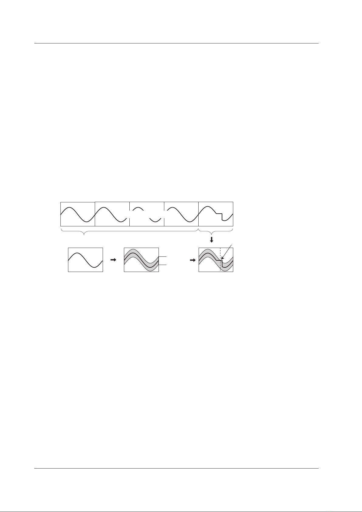
Wave Window Trigger
The DL850E/DL850EV creates real-time templates (Wave Window) using a number of cycles directly preceding
the current waveforms. The DL850E/DL850EV compares the current waveforms to the real-time templates and
triggers if one of the current waveforms falls outside of its real-time template.
Reference cycles (example: the waveforms
for the four previous cycles) Current waveform
Real-time template
Average waveform
+ tolerance
Average of 1, 2, or
4 cycles
The DL850E/DL850EV
compares the current
waveform to the real-time
template and triggers if the
current waveform falls
outside of the real-time
template.
Measured waveform
Tolerance
Trigger
Trigger Source
Trigger source refers to the signal that is used to check the specified trigger conditions. You can set the trigger
source to an analog signal, logic signal, time, external signal, or power line signal. Select the appropriate trigger
source for the trigger type.
Trigger Level
Trigger level refers to the signal level used as a reference for detecting a signal’s rising and falling edges or high
and low states. With simple triggers such as the edge trigger, the DL850E/DL850EV triggers when the trigger
source level passes through the specified trigger level. The range and resolutions that you can use to set the
trigger level vary depending on the type of signal being measured.
Waveform Acquisition
Based on the data that has been stored in the acquisition memory, the DL850E/DL850EV performs various
operations, such as displaying waveforms on the screen, computing, measuring cursors, and automatically
measuring waveform parameters.
You can set the number of data points to store in the acquisition memory (the record length), enable or disable
the sample data averaging feature, and so on.
1 Main Features

1-5
IM DL850E-01EN
Record Length
Record length refers to the number of data points that are stored to the acquisition memory for each channel.
Display record length refers to the data points from the data stored in the acquisition memory that are displayed
on the screen. Normally, the acquisition-memory record length and display record length are the same, but the
time axis setting may cause them to differ. When you change the time axis setting, the sample rate and record
length also change.
On the standard model of the DL850E/DL850EV, you can set the record length to a value between 1 kpoint and
250 Mpoint. Depending on the model, you can set the record length to a value of up to 2 Gpoint.
Acquisition Mode
Specify how the DL850E/DL850EV processes the sampled data, stores it in the acquisition memory, and uses it
to display waveforms. There are four acquisition modes: Normal, Envelope, Averaging, and BoxAverage.
Hard Disk Recording
When measurement starts, you can record data to an external hard disk that supports eSATA (external Serial
ATA; /HD0 option) or to an internal hard disk (/HD1 option).* The recorded data is saved to files automatically.
You can load the saved data using the DL850E/DL850EV and convert it to a format that you can analyze on a
PC (ASCII or floating point).
* Models with the /HD0 option are equipped with eSATA connectors. You need to purchase a hard disk that
supports eSATA separately.
History
When waveforms are being measured, the waveform data stored in the acquisition memory as a result of a
trigger occurrence is displayed as a waveform on the DL850E/DL850EV screen and can be viewed. When
waveform acquisition is being triggered in succession and an abnormal waveform appears, it is impossible to
stop acquisition before a new waveform appears on the screen. Normally, it would be impossible to view the
abnormal waveform. However, with the history feature, you can view the past waveform data (history waveforms)
stored in the acquisition memory when waveform acquisition is stopped. You can select specific history
waveforms and display them.
You can also search through the history waveforms for waveforms that meet specified conditions.
•Zone Search
The DL850E/DL850EV searches for history waveforms that passed (or did not pass) through a specified
search zone.
• Waveform Parameter Search
The DL850E/DL850EV searches for waveforms whose measured waveform parameter values meet (or do
not meet) specified conditions.
Dual Capturing
You can use dual capturing to simultaneously record a trend at a low sampling speed in roll mode and at a high
sample rate. This is useful for capturing fast phenomenon while observing a trend over a long period of time.
Captured waveforms
(high-speed sampling)
Update mode display
Main waveforms
(low-speed sampling)
Roll mode display
Sample rate:
Faster than that of the
main waveform
Sample rate:
100 kS/s or less
1 Main Features

1-6 IM DL850E-01EN
Waveform Display
The DL850E/DL850EV has a main window for displaying normal time-domain waveforms, zoom windows for
displaying zoomed time-axis waveforms, and X-Y windows for displaying X-Y waveforms. In addition, you can
split screens and change the sizes of waveform display areas so that waveforms and measured values are
easier to see and display an FFT window that shows the results of FFT analysis.
Zooming along the Time Axis (GIGAZoom)
You can magnify displayed waveforms along the time axis. The zoomed waveforms of two locations can be
displayed simultaneously (the dual zoom feature). This feature is useful when you set a long acquisition time and
want to observe a portion of the waveform closely.
Displaying X-Y Waveforms
You can observe the correlation between two waveform signal levels by displaying one signal level on the
X-axis (horizontal axis) and a second signal level on the Y-axis (vertical axis). You can display X-Y waveforms
at the same time as normal T-Y (time and signal level) waveforms. You can display up to four overlapping X-Y
waveforms in both Window1 and Window2. Because multiple X-Y waveforms can be displayed, it is easy to
compare the relationships between phases. You can use this feature to evaluate DC motors using Lissajous
waveforms.
Snapshot
You can continue displaying a waveform on the screen as a snapshot waveform after the screen has been
updated and the waveform has been cleared in update mode or after the waveform has left the screen in roll
mode. Snapshot waveforms appear in white. You can compare them with new waveforms. You can also save
and print snapshot waveforms as screen captures.
Waveform Computation and Analysis
Waveform Computation
You can perform basic arithmetic, binarization, FFT (power spectrum), and phase shifting (display the waveform
with its phase shifted). On models with the /G2 option, you can use a rich variety of functions (square root,
trigonometric functions, differentiation, integration, digital filtering, six types of FFT functions, and so on) to define
up to eight equations.
Cursor Measurement
There are cursors for T-Y (time-axis), X-Y, and FFT waveforms. You can position a cursor over a waveform to
view the various measured values at the intersection of the cursor and the waveform.
Automated Measurement of Waveform Parameters
You can use this feature to automatically measure waveform levels, maximum values, frequencies, and other
values. For up to 100 Mpoint of waveform data, you can measure 29 waveform parameters (including the delay
between channels) that relate to the voltage axis, time axis, and waveform area.
•You can display a total of 32 measured values for all the waveforms.
• You can save a total of 64000 items of data for all the waveforms.
• You can also perform computations on measured waveform parameter values.
• You can display the following statistics for the specified waveform parameter.
The maximum value (Maximum), minimum value (Minimum), average value (Average), standard deviation
(SDev), and number of measured values used to calculate statistics (Count)
1 Main Features

1-7
IM DL850E-01EN
There are three statistical processing methods:
• Normal statistical processing
While acquiring waveforms, the DL850E/DL850EV measures the measurement items and calculates the
statistics of the waveforms that it has acquired so far.
• Cyclic statistical processing (measurement and statistical processing are performed for each period)
The DL850E/DL850EV divides the waveform into periods starting at the left side of the screen (the oldest
waveform) and moving to the right side of the screen, measures the selected measurement items within each
period, and performs statistical processing on the measurement items.
•Statistical processing of history waveforms
The DL850E/DL850EV measures the measurement items and calculates the statistics of history waveforms.
Measurement and statistical processing begin with the oldest waveform.
GO/NO-GO Determination
This feature is useful for signal testing on production lines and for tracking down abnormal phenomena. The
DL850E/DL850EV determines whether the waveform enters the specified range. When the DL850E/DL850EV
returns a GO (or NO-GO) result, specified actions are performed.
Determination Methods
•Waveform Zone
The DL850E/DL850EV returns GO/NO-GO results based on whether waveforms leave or enter the zone that
you create using a base waveform.
The DL850E/DL850EV returns a GO or
NO-GO judgment according to the
determination condition.
Specified zone
Determination
area
• Waveform Parameter
Set the upper and lower limits for automated measurement values of waveform parameters. The DL850E/
DL850EV performs GO/NO-GO determination based on whether the values are within or outside of the limits.
Actions Performed according to Determination Results
The DL850E/DL850EV can print and save screen captures, save waveform data, beep, and send e-mails
according to the results of GO/NO-GO determination.
1 Main Features

1-8 IM DL850E-01EN
Notes about Using the 16-CH Voltage Input Module (720220),
Notes about Using the 16-CH Temperature/Voltage Input Module (720221)
Notes about Using the 16-CH Voltage Input Module (720220)
While normal voltage input modules have two main channels for analog input, the 16-CH voltage input module
has 16 sub channels for analog input. The 16-CH voltage input module samples the measured sub channels in
order.
Sub_Ch1
Sub_Ch2
Sub_Ch3
Sub_Ch16
•
•
•
Sub_Ch1
Sub_Ch2
Sub_Ch3
Sub_Ch16
5 μs
When the number of measured sub channels is 16
(all the sub channels are measured)
Timing of sub
channel
sampling
Main channel
sample clock
100 μs
Main channel sample rate: 200 kS/s
Sub channel sample rate: 10 kS/s
Sub_Ch1
Sub_Ch2
Sub_Ch3
Sub_Ch16
5 μs
Timing of sub
channel
sampling
Main channel
sample clock
•
•
•
Sub_Ch1
Sub_Ch2
Sub_Ch3
Sub_Ch16
5 μs
Timing of sub
channel
sampling
Main channel
sample clock
10 μs 10 μs
When the number of measured sub channels is 2
(sub channels 1 and 16 are measured)
Sub channel sample rate: 100 kS/s
• The 16-CH voltage input module uses only the odd main channels of the slot that it is inserted into. It cannot
use the slot’s even main channels.
• If you do not want to measure an individual sub channel, turn its input coupling off. Sub channels whose input
coupling has been turned off are not scanned.
• The maximum sample rate of the 16-CH voltage input module is 200 kS/s (when only one sub channel is
measured). The maximum sample rate per sub channel varies depending on the main channel sample rate
and the number of measured sub channels. For information about sample rates, see appendix 1 in the Getting
Started Guide, IM DL850E-03EN.
•The sample rate that is displayed on the screen is the sample rate of the main channel.
• The record length of each sub channel varies depending on the set record length and the number of
measured sub channels.
Record length of each sub channel ≤ set record length/number of measured sub channels
• The timing of waveform acquisition is different for each sub channel, but all the sub channels are stored in the
acquisition memory as if they had been sampled at the same timing. This means that the sampling times of
the acquired waveform data are different from the sampling times of the actual applied waveforms.
1 Main Features

1-9
IM DL850E-01EN
• Because the waveform data stored in the acquisition memory is used to display waveforms on the screen, the
data of all sub channels is displayed as if though it were sampled at the same timing.
• The following operations are performed on the waveform data stored in the acquisition memory: waveform
zooming, cursor measurement, the automated measurement of waveform parameters, computation, FFT,
waveform searches, and the loading and saving of waveform data.
• GO/NO-GO determination and the display and searching of history waveforms are not performed on sub
channels.
•When you execute auto setup on the 16-CH voltage input module, sub channel on/off settings and settings
that relate to the horizontal axis (TIME/DIV) are not changed.
• Wire all the L input terminals for all the sub channels on the same module to the same potential. The L input
terminals of the sub channels are common. Because the L input terminals are electrically connected inside
the DL850E/DL850EV, connecting different potentials to them could result in short circuiting and damage to
the 16-CH voltage input module.
For information about the terminal arrangement, see section 3.13 in the Getting Started Guide, IM DL850E-
03EN.
•For information about attaching and removing the terminal block and connecting and removing wires from the
terminal block, see section 3.13 in the Getting Started Guide, IM DL850E-03EN.
Notes about Using the 16-CH Temperature/Voltage Input Module (720221)
In comparison with normal temperature modules, which can receive input from two thermocouples, the 16-CH
temperature/voltage input module has sub channels that enable it to receive input from 16 thermocouples
through a scanner box. You can also measure the voltage of 16 channels. The 16-CH temperature/voltage input
module samples the measured sub channels in order.
•The 16-CH temperature/voltage input module uses only the odd main channels of the slot that it is inserted
into. It cannot use the slot’s even main channels.
• If you do not want to measure a given sub channel, turn its input coupling off. Sampled data is not acquired
for channels whose input coupling is turned off.
• Regardless of the number of measured sub channels, the actual maximum sample rate is 100 kS/s. The
sample rate per sub channel varies depending on the main channel sample rate. For information about
sample rates, see appendix 1 in the Getting Started Guide, IM DL850E-03EN.
• The sample rate that is displayed on the screen is the sample rate of the main channel.
• Record length of each sub channell ≤ set record length/16
• The timing of waveform acquisition is different for each sub channel, but all the sub channels are stored in the
acquisition memory as if they had been sampled with the same timing. This means that the sampling times of
the acquired waveform data are different from the sampling times of the actual applied waveforms.
• Because waveforms on the screen are displayed using the waveform data stored in the acquisition memory,
the data of all sub channels is displayed as though it were sampled with the same timing.
• The waveforms displayed on the screen are updated at the set data update period regardless of the number
of measured sub channels. The previous value is stored repeatedly in acquisition memory until the value
changes. Saved waveform data is treated in the same manner.
•The waveform data stored in the acquisition memory is used when you perform the following operations:
waveform zooming, cursor measurement, the automated measurement of waveform parameters,
computation, FFT, waveform searches, and the loading and saving of waveform data.
• GO/NO-GO determination and the display and searching of history waveforms are not performed on sub
channels.
•When you execute auto setup on the 16-CH temperature/voltage input module, sub channel on/off settings
and horizontal axis (TIME/DIV) settings are not changed.
• Connect the 16-CH temperature/voltage input module to the scanner box with a cable and then connect
a thermocouple to the scanner box to perform temperature measurements. For information about how to
connect thermocouples to the scanner box’s terminal block, see section 3.14 in the Getting Started Guide, IM
DL850E-03EN.
1 Main Features
2-1
IM DL850E-01EN
2 Vertical Axis
This section explains how to configure the signal input settings and the amplitude-direction display settings. The
items that can be set vary depending on the installed modules.
Input Settings
CH1 to CH16
The channel menu that corresponds to the key you pressed appears. You can set the various vertical axis
settings for each channel.
ALL CH
You can configure the settings of all channels while viewing the settings in a list. You can also copy the various
vertical axis settings of one channel to another channel. There are some items that cannot be configured from
the ALL CH menu.
DL850E/DL850EV Measurement Items
When the DL850E/DL850EV is equipped with the modules listed below, it can measure voltage, temperature,
strain, acceleration, frequency, logic, CAN bus signals, LIN bus signals, and so on.
• Voltage measurement
701250 (HS10M12), 701251 (HS1M16), 701255 (NONISO_10M12), 701267 (HV (with RMS)),
720210 (HS100M12), 701261 (UNIVERSAL), 701262 (UNIVERSAL (AAF)), 701265 (TEMP/HPV),
701275 (ACCL/VOLT)
You can install up to four 720210 modules, and these modules must be installed in the top slots.
•Voltage measurement (for the 16-CH Voltage Input Module)
720220 (16CH VOLT)
• Temperature measurement
701261 (UNIVERSAL), 701262 (UNIVERSAL (AAF)), 701265 (TEMP/HPV)
•Temperature measurement (for the 16-CH Temperature/Voltage Input Module)
720221 (16CH TEMP/VOLT)
• Strain measurement
701270 (STRAIN_NDIS), 701271 (STRAIN_DSUB)
• Acceleration measurement
701275 (ACCL/VOLT)
• Frequency measurement
701280 (FREQ)
• Logic measurement
720230 (LOGIC)
• CAN Bus Signal Monitoring
720240 (CAN MONITOR), 720241 (CAN & LIN)
These modules can be used only with the DL850EV. You can install up to a total of two 720240 or 720241
modules in slots 7 and 8.
•LIN Bus Signal Monitoring
720241 (CAN & LIN)
This module can be used only with the DL850EV. You can install up to two 720241 modules in slots 7 and 8.
You can use auto setup to automatically configure the appropriate settings (such as vertical axis, horizontal
axis, and trigger settings) for the input signal. This feature is useful when you are not sure what type of signal
will be applied to the DL850E/DL850EV. The auto setup feature will not work properly on some input signals.
Also, there are some modules with which the auto setup feature cannot be used.
Digital Filter and Real Time Math (Optional)

2-2 IM DL850E-01EN
Voltage Measurement
For voltage measurement, the items that have to be set for each input signal (CH1 to CH16) include vertical
scales, the vertical positions, input coupling, probe attenuation, the bandwidth limit, the zoom method, the offset,
waveform inversion, trace settings, and linear scaling.
You can measure voltage by connecting probes, measurement leads, etc. to one of the following voltage
measurement modules: 701250 (HS10M12), 701251 (HS1M16), 701255 (NONISO_10M12), 701267 (HV (with
RMS)), 720210 (HS100M12), 701261 (UNIVERSAL), 701262 (UNIVERSAL (AAF)), 701265 (TEMP/HPV),
701275 (ACCL/VOLT).
For the probe connection method, see section 3.5 in the Getting Started Guide, IM DL850E-03EN. For the
measurement lead connection method, see section 3.7.
•Waveform Display (Display)
• Labels (Label)
•Vertical Scale (SCALE knob)
• Waveform Vertical Position (Vertical POSITION knob)
• Input Coupling (Coupling)
• Probe Attenuation and Current-to-Voltage Conversion Ratio (Probe)
• Bandwidth (Bandwidth)
• Zoom Method (V Scale)
• Zooming by Setting a Magnification (V Zoom)
• Zooming by Setting Upper and Lower Display Limits (Upper/Lower)
• Offset (Offset)
• DC Offset Cancel (DC Offset Cancel)
• Gain Adjustment (Gain)
• Trace Settings (Trace Setup)
• Inverted Waveform Display (Invert)
• Linear Scaling (Linear Scale)
• RMS Measurement
Waveform Display (Display)
Select whether to display each channel’s input signal waveform.
• ON: Displays the waveform
• OFF: Does not display the waveform
Labels (Label)
You can specify a name of up to sixteen characters in length for each channel.
You can set whether to display labels using the DISPLAY menu.
• The waveform display on/off setting changes to the waveform acquisition on/off setting in cases such as
during hard disk recording and when an increase in the record length places a limitation on the number of
channels that can be used.
•The specified display label is used in labels, scale values, the numeric display, and cursor-measurement
values.
• Depending on the display and zoom formats, label names may not appear when the waveform display is
narrow.
2 Vertical Axis

2-3
IM DL850E-01EN
Vertical Scale (SCALE knob)
Voltage Scale Setting
The vertical scale is used to adjust the displayed waveform amplitude so that you can easily view signals. Set
the vertical scale by voltage per grid square (V/div) or current per grid square (A/div) on the screen.
Use the SCALE knob to set the vertical scale for each channel and sub channel.
The same SCALE knob is used to adjust the scale of each channel and sub channel.
To change the vertical scale of a channel, press the key from CH1 to CH16 that corresponds to the channel.
To change the vertical scale of a sub channel, press an odd channel key from CH1 to CH15, and then press the
soft key that corresponds to the sub channel.
The vertical scale changes when you switch to an input attenuator with a different attenuation. You can change
the scale in steps like this: 1 V/div -> 2 V/div -> 5 V/div.
Example
1 div = 1.000 V
If 1.000 V/div is changed to 0.500 V/div
1 div = 0.500 V
Vertical position mark
Ground level mark
• While waveform acquisition is stopped, turning the SCALE knob will not change the displayed waveform.
The changed V/div value will be applied the next time that waveform acquisition is started.
• While waveform acquisition is stopped, turning the SCALE knob will not change the cursor-measurement
values or the automated measurement values of waveform parameters, they will continue to be based on
the V/div value at the time of measurement.
Selectable range of V/div
The selectable range varies as shown below depending on the input module.
Input Module Selectable Range
701250 (HS10M12) 5 mV/div to 20 V/div
701251 (HS1M16) 1 mV/div to 20 V/div
701255 (NONISO_10M12) 5 mV/div to 20 V/div
701267 (HV (with RMS)) 20 mV/div to 200 V/div
701261 (UNIVERSAL) 5 mV/div to 20 V/div
701262 (UNIVERSAL (AAF)) 5 mV/div to 20 V/div
701265 (TEMP/HPV) 0.1 mV/div to 10 V/div
701275 (ACCL/VOLT) 5 mV/div to 10 V/div
720210 (HS100M12) 10 mV/div to 20 V/div
720220 (16CH VOLT) 200 mV/div to 2 V/div
720221 (16CH TEMP/VOLT) 1 mV/div to 2 V/div
These values are for when the probe attenuation is 1:1. Multiply the values by 10 when the attenuation is
10:1, by 100 when the attenuation is 100:1, and by 1000 when the attenuation is 1000:1.
2 Vertical Axis
Other manuals for DL850E
3
This manual suits for next models
1
Table of contents
Other YOKOGAWA Laboratory Equipment manuals


