YOKOGAWA MVAdvanced MV1000 User manual

Service
Manual
Yokogawa Electric Corporation
MV1000/MV2000
SM MV1000-01E
1st Edition

i
SM MV1000-01E
Important Notice to the User
• This manual contains information for servicing YOKOGAWA’s MV1000 and MV2000.
Check the serial number to conrm that this is the correct service manual for the
instrument to be serviced. Do not use the wrong manual.
•Before any maintenance and servicing, read all safety precautions carefully.
• Only properly trained personnel may carry out the maintenance and servicing
described in this service manual.
•Do not disassemble the instrument or its parts, unless otherwise clearly permitted by
this service manual.
•Do not replace any part or assembly, unless otherwise clearly permitted by this service
manual.
•In principle, Yokogawa Electric Corporation (YOKOGAWA) does not supply parts
other than those listed in the customer maintenance parts list in this service manual
(mainly modules and assemblies). Therefore if an assembly fails, the user should
replace the whole assembly and not components within the assembly (see “Note”). If
the user attempts to repair the instrument by replacing individual components within
the assembly, YOKOGAWA assumes no responsibility for any consequences such as
defects in instrument accuracy, functionality, reliability, or user safety hazards.
•YOKOGAWA does not offer more detailed maintenance and service information than
that contained in this service manual.
•All reasonable efforts have been made to assure the accuracy of the content of
this service manual. However, there may still be errors such as clerical errors or
omissions. YOKOGAWA assumes no responsibility of any kind concerning the
accuracy or contents of this service manual, nor for the consequences of any errors.
•All rights reserved. No part of this service manual may be reproduced in any form
or by any means without the express written prior permission of YOKOGAWA. The
contents of this manual are subject to change without notice.
Note
YOKOGAWA instruments have been designed in a way that the replacement of electronic parts
can be done on an assembly (module) basis by the user. YOKOGAWA instruments have also
been designed in a way that troubleshooting and replacement of any faulty assembly can be
done easily and quickly. Therefore, YOKOGAWA strongly recommends replacing the entire
assembly over replacing parts or components within the assembly. The reasons are as follows:
• The instruments use high-performance microprocessors, large scale CMOS gate arrays,
and surface-mount components to provide state-of-the-art performance and functions.
• Repair of components can only be performed by specially trained and qualified maintenance
personnel with special highly-accurate tools, including costly ones.
• When taking the service life and cost of the instruments into consideration, the replacement
of assemblies offers the user the possibility to use YOKOGAWA instruments more effectively
and economically with a minimum in downtime.
1st Edition: April 2008 (YK)
All Rights Reserved, Copyright © 2006 Yokogawa Electric Corporation

SM MV1000-01E
ii
Trademark
• vigilantplant and MVAdvanced are registered trademarks or trademarks of Yokogawa
Electric Corporation.
•Adobe and Acrobat are registered trademarks or trademarks of Adobe Systems
Incorporated.
•Company and product names that appear in this manual are registered trademarks or
trademarks of their respective holders.
•The company and product names used in this manual are not accompanied by the
registered trademark or trademark symbols (® and ™).
Revisions
1st Edition: April 2008

iii
SM MV1000-01E
Introduction
This manual contains information for servicing YOKOGAWA’s MV1000 and MV2000.
WARNING
This service manual is to be used by properly trained personnel only. To avoid
personal injury, do not perform any servicing unless you are qualified to do
so. Refer to the safety precautions prior to performing any servicing. Even if
servicing is carried out according to this service manual, or by qualified personnel,
YOKOGAWA assumes no responsibility for any result occurring from that servicing.
Safety Standards and EMC Standards
The MV conforms to IEC safety class I (provided with terminal for protective grounding),
Installation Category II, Measurement Category II (CAT II), and EN61326 (EMC
standard), class A (use in a commercial, industrial, or business environment).
The MV is designed for indoor use.
Safety Precautions
The general safety precautions described here must be observed during all phases of
operation. If the MV is used in a manner not described in this manual, the protection
provided by the MV may be impaired. Yokogawa Electric Corporation assumes no liability
for the customer’s failure to comply with these requirements.
WARNING
• Use the Correct Power Supply
Ensure that the source voltage matches the voltage of the power supply before
turning ON the power. In the case of a desktop type, ensure that it is within the
maximum rated voltage range of the provided power cord before connecting the
power cord.
•Use the Correct Power Cord and Plug
To prevent electric shock or fire, be sure to use the power cord supplied by
YOKOGAWA. The main power plug must be plugged into an outlet with a
protective ground terminal. Do not disable this protection by using an extension
cord without protective earth grounding.
•Connect the Protective Grounding Terminal
Make sure to connect the protective grounding to prevent electric shock before
turning ON the power.
The power cord that comes with the desktop type is a three-prong type power
cord. Connect the power cord to a properly grounded three-prong outlet.
•Do Not Impair the Protective Grounding
Never cut off the internal or external protective grounding wire or disconnect the
wiring of the protective grounding terminal. Doing so invalidates the protective
functions of the instrument and poses a potential shock hazard.
•Do Not Operate with Defective Protective Grounding
Do not operate the instrument if the protective grounding might be defective.
Also, make sure to check them before operation.

SM MV1000-01E
iv
• Do Not Operate in an Explosive Atmosphere
Do not operate the instrument in the presence of flammable liquids or vapors.
Operation in such an environment constitutes a safety hazard.
Prolonged use in a highly dense corrosive gas (H2S, SOx, etc.) will cause a
malfunction.
•Do Not Remove Covers
The cover should be removed by YOKOGAWA’s qualified personnel only.
Opening the cover is dangerous, because some areas inside the instrument
have high voltages.
•Ground the Instrument before Making External Connections
Connect the protective grounding before connecting to the item under
measurement or control unit.
•Damage to the Protection
Operating the instrument in a manner not described in this manual may damage
the instrument’s protection.
Safety Symbols Used on Equipment and in Manual
“Handle with care.” To avoid injury and damage to the instrument, the
operator must refer to the explanation in the manual.
Protective ground terminal
Functional ground terminal (do not use this terminal as a protective ground
terminal.)
Alternating current
ON (power)
OFF (power)
Direct current
Conventoins Used in Manual
WARNING Calls attention to actions or conditions that could cause serious
or fatal injury to the user, and precautions that can be taken to
prevent such occurrences.
Calls attentions to actions or conditions that could cause light
injury to the user or damage to the instrument or user’s data,
and precautions that can be taken to prevent such occurrences.
CAUTION

v
SM MV1000-01E
Overview of This Manual
This manual is meant to be used by qualified personnel only. Make sure to read the
safety precautions at the beginning of this manual as well as the warnings and cautions
contained in the chapters relevant to any servicing you may be carrying out.
This manual contains the following chapters.
Chapter 1 Principles of Operation
Describes the principles of operation of the instrument.
Chapter 2 Troubleshooting
Lists problems that can occur and gives corrective actions.
Chapter 3 Testing
Gives procedures for testing the characteristics of the instrument.
Chapter 4 Adjustments
Explains how to adjust the instrument.
Chapter 5 Schematic Diagram
Provides a system conguration diagram.
Chapter 6 Customer Maintenance Parts List
Contains exploded views and a list of replaceable parts.
Chapter 7 Replacing Parts
Describes how to replace parts.
Specifications are not included in this manual. For specifications, refer to the MV1000/
MV2000 User’s Manual (IM MV1000-01E).

SM MV1000-01E
vi
Contents
Important Notice to the User..............................................................................................................i
Trademark......................................................................................................................................... ii
Revisions ..........................................................................................................................................ii
Introduction ...................................................................................................................................... iii
Safety Standards and EMC Standards............................................................................................ iii
Safety Precautions........................................................................................................................... iii
Safety Symbols Used on Equipment and in Manual........................................................................ iv
Conventuins Used in Manual...........................................................................................................iv
Overview of This Manual ..................................................................................................................v
Chapter 1 Principles of Operation
1.1 Principles of Operation ........................................................................................................ 1-1
Chapter 2 Troubleshooting
2.1 Failure Analysis Flow Chart ................................................................................................. 2-1
2.2 Troubleshooting Checklist.................................................................................................... 2-4
Chapter 3 Testing
3.1 Acceptance Test .................................................................................................................. 3-1
3.2 Self Diagnostic Test ............................................................................................................. 3-2
3.3 Performance Test................................................................................................................. 3-3
Test Environment ................................................................................................................. 3-3
Test Instruments .................................................................................................................. 3-3
Instrument Operation ........................................................................................................... 3-3
Tests .................................................................................................................................... 3-3
3.4 Test Procedures................................................................................................................... 3-4
Insulation Resistance........................................................................................................... 3-4
Protective Grounding ........................................................................................................... 3-4
Withstand Voltage................................................................................................................ 3-5
Measurement Accuracy ....................................................................................................... 3-6
Reference Junction Compensation Accuracy ...................................................................... 3-8
Battery Backup .................................................................................................................... 3-8
Pulse Input Function ............................................................................................................ 3-9
Chapter 4 Adjustments
4.1 Before Making Adjustments ................................................................................................. 4-1
Environment......................................................................................................................... 4-1
Instrument Operation ........................................................................................................... 4-1
Note ..................................................................................................................................... 4-1
4.2 Adjusting the A/D Converters............................................................................................... 4-2
Chapter 5 Schematic Diagram
5.1 Schematic Diagram (MV1000)............................................................................................. 5-1
5.2 Schematic Diagram (MV2000)............................................................................................. 5-2

vii
SM MV1000-01E
1
2
3
4
5
6
7
Contents
Chapter 6 Customer Maintenance Parts List
6.1 Customer Maintenance Parts List (MV1000)....................................................................... 6-1
6.2 Customer Maintenance Parts List (MV2000)....................................................................... 6-9
Chapter 7 Replacing Parts
7.1 Introduction .......................................................................................................................... 7-1
Replaceable Parts ............................................................................................................... 7-1
If Servicing is Required........................................................................................................ 7-1
7.2 Recommended Replacement Periods for Worn Parts......................................................... 7-2
1-1
SM MV1000-01E
Principles of Operation
1
2
3
4
5
6
7
Chapter 1 Principles of Operation
1.1 Principles of Operation
The following explains the principles of operation of the MV.
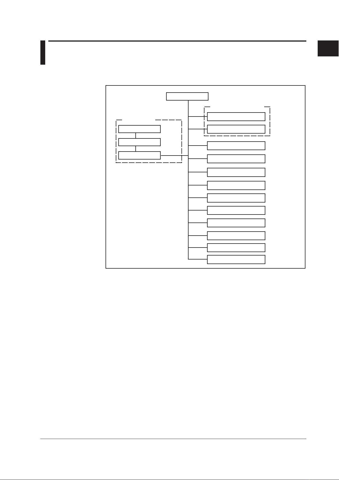
Block Diagram
Data storage functions
Input section
Calculation function
Alarm
Communication function
(optional)
Input terminal
Scanner
A/D
CPU
External storage
Internal memory
Display
Remote control
Relay contact (optional)
(optional)
Pulse input
Transmitter power supply (optional)
USB port
Key
Input Terminal Section
For connecting the measurement input signal wires. The terminals can be used for DC
voltage, thermocouple, resistance temperature measurement, and contact input.
•The reference junction compensation circuit for thermocouples is built in.
• Proven transistor method for measuring the temperature of the terminals.
• Metal core construction used in the internal printed circuit boards to equalize
temperature.
•Input terminals removable.
Scanner Section
Switches the measured input signal (channel). The input signal switching section uses
highly reliable solid state relays (SSR).
A/D Conversion Section
Converts analog signals to digital signals. It is a PWM (pulse width modulation) type
converter. A/D converter calibration data is stored in an EEPROM.
For the correspondence between input channels and A/D converters, see “Measurement
Accuracy” on page 3-6.

1-2 SM MV1000-01E
Saving Data
The capacity of the internal memory is either 80 MB (standard memory) or 200 MB
(expansion memory).
The CF card can be used as an external memory medium.
Display/Keys
The MV uses an LCD display. You can control the MV with key operations.
Calculation
You can calculate the difference between two measurement inputs, perform linear
scaling, square roots, calibration correction, and other computations.
Alarms
Alarm functions include upper limit alarm and lower limit alarm.
Other Functions
Serial/Ethernet Communication
The MV can communicate with other instruments via the Ethernet, RS-232, or
RS-422/485 interface (with the serial communication option).
Remote Control/Pulse Input
Record start and other operations can be controlled using external signals (with the
optional remote control function).
Counts the number of pulses for each measruement (with the pulse input option).
Relay Output
The MV can output alarms or FAIL/Status (optional).
Transmitter Power Supply Output
The MV can output 24 VDC for use as a power supply for transmitters (optional).
USB Port
Allows connection with USB keyboard and USB flash memory devices.
1.1 Principles of Operation

2-1
Troubleshooting
SM MV1000-01E
1
2
3
4
5
6
7
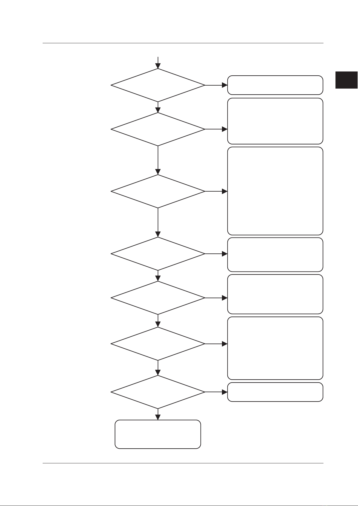
2.1 Failure Analysis Flow Chart
When a failure occurs, refer to the flow chart below for corrective actions.
See No. 5 of the checklist
in section 2.2.
See No. 1 of the checklist in
section 2.2.
Has the backlight gone out due
to the LCD’s backlight saver?
Other than the display,
is the instrument functioning
normally?
Is an appropriate power
supply being input?
Is the power supply wired
correctly?
Is the power switch* ON?
Does the switch operate
normally?
Doesn’t function at all
(nothing is displayed)
Turn the switch ON correctly.
Wire it correctly.
Supply power of voltage and
frequency that conforms to
the specifications.
Restore the original brightness
through key operation.
Try replacing the backlight.
YES
NO
YES
NO
YES
NO
YES
NO
NO
YES
NO
YES
Has the instrument
been operated longer than the
recommended replacement period
for the backlight (5 years)?
Chapter 2 Troubleshooting

2-2 SM MV1000-01E
Is the key lock set?
Have measures against
external noise been taken?
See No. 4 of the checklist.
See No. 2, 3, 7, 9, and 10 of the
checklist in section 2.2.
Release the key lock setting.
Keys do not operate correctly
If there is a problem with a display
screen or other function
NO
YES
YES
NO
• Keep measurement input,
communication, and other
wires and cables away from
noise sources.
• Be sure to ground all
instruments.
• Use shielded cables for
wiring measurement input,
communication, and other
circuits.
• Use isolation transformers
on power supply lines.
• Insert filters on power supply
lines.
• If inductive loads are used
on alarm lines, insert surge
absorbers in the lines.
Note
If menu items required for screen menus or function menus are not displayed, check menu
customization settings.
Is the memory medium
(CF card) working normally?
Is it a recommended
device?
See No. 8 of the checklist
in section 2.2.
Replace the memory medium
(CF card) with a new one.
Malfunction of external medium
(CF card)
YES
NO
2.1 Failure Analysis Flow Chart
2-3
Troubleshooting
SM MV1000-01E
1
2
3
4
5
6
7
2.1 Failure Analysis Flow Chart
Is the input wiring correct?
Is a constant ambient
temperature maintained?
Have appropriate measures
against noise been taken?
Are the range, span, and other
input settings appropriate?
Does the input meet the
input specifications?
Problems related to measurement
YES
NO
YES
NO
YES
NO
YES
NO
YES
NO
Ensure that the input
specifications are met.
Set them correctly.
• Enter range, span, and other
input settings that are
appropriate.
• When using the calibration
correction function, check the
settings for the calibration
correction.
• Keep input wires and cables
away from noise sources.
• Be sure to ground the recorder.
• Ground the measured object
properly.
• For thermocouple measurement,
insulate points of contact
between the measured object and
thermocouple.
• Use shielded cables for input
wiring.
• Change the integral time setting
of the A/D converter.
• Use moving average on the input.
• Attach input terminal covers.
• To avoid temperature changes in
the vicinity of input terminals,
keep fan ventilation holes clear,
and keep hot objects away.
• Ensure correct polarity when
wiring.
• Check that terminal wires are
securely connected.
• Do not ground RTDs.
• Replace broken thermocouples.
• Do not connect other instruments
with thermocouples in parallel.
If you must connect it in parallel,
consider using a double element
thermocouple, refraining from
using burnout detection, or
implementing other measures.
• Use one earth connection when
connecting the MV to another
instrument.
Are the RJC
settings and TC, RTD type
settings correct?
See No. 6 of the checklist
in section 2.2.
YES
NO
Are other instruments
connected in parallel?
NO
YES

2-4 SM MV1000-01E
2.2 Troubleshooting Checklist
The table below describes the most common types of failures and their corrective
actions.
No. Phenomenon
Action
Description
Refer to Chapter 6
Check
Adjust
Replace
*1 Part Name MV1000 MV2000
Page Item Page Item
1
The instrument
doesn’t start
even though
the power is
ON
Power supply cable connection/wiring - - - - -
MAIN POWER BOARD ASSEMBLY
12V POWER BOARD ASSEMBLY Power Assembly 6-3 2 6-12 2
MAIN BOARD ASSEMBLY Main PBA 6-3 4 6-12 11
SUB BOARD ASSEMBLY Sub PCB Assembly 6-3 5 6-12 13
2 FAIL state
MAIN BOARD ASSEMBLY Main PBA 6-3 4 6-12 11
SUB BOARD ASSEMBLY Sub PCB Assembly 6-3 5 6-12 13
OPTION TERMINAL ASSEMBLY Option Terminal Assembly 6-5 12 6-14 12, 13
3
Abnormal
functioning of
memory
(backup)
Battery connection Battery Assembly 6-3 6 6-12 12
Battery voltage
(must be +3.0 V or more) - - - - -
MAIN BOARD ASSEMBLY Main PBA 6-3 4 6-12 11
SUB BOARD ASSEMBLY Sub PCB Assembly 6-3 5 6-12 13
4Key operation
abnormality
Check the FFCs*3 for key wiring
(whether pulled out or damaged) - - - - -
SW BOARD ASSEMBLY Bezel Assembly 6-2 1 6-10 1
CONNECTION BOARD ASSEMBLY Bezel Assembly 6-2 1 6-10 1
MAIN BOARD ASSEMBLY Main PBA 6-3 4 6-12 11
5LCD display
not normal
Check the FFCs*3 for key wiring
(whether pulled out or damaged) - - - - -
MAIN BOARD ASSEMBLY Main PBA 6-3 4 6-12 11
SUB BOARD ASSEMBLY Sub PCB Assembly 6-3 5 6-12 13
CONNECTION BOARD ASSEMBLY Bezel Assembly 6-2 1 6-10 1
Back Light Unit of LCD ASSEMBLY Bezel Assembly 6-2 1 6-10 1
LCD ASSEMBLY Bezel Assembly 6-2 1 6-10 1
6
Large
measurement
error
Temperature
measurement
abnormal
Keep input wires away from noise
sources (through distance and
shielding, etc.)
- - - - -
Check that the input terminals are not
disconnected from the instrument - - - - -
Check that the input terminal cover is
not loose - - - - -
Check that the RJC (INT/EXT) setting
is correct - - - - -
AD SCANNER BOARD ASSEMBLY AD-STD/ISO 6-3 7, 8 6-12 24, 25
26, 27
7
Fluctuation
in measured
values
Does the integral time setting of the
A/D converter match the power supply
frequency?
- - - - -
Keep input wires away from noise
sources (through distance and
shielding, etc.)
- - - - -

2-5
Troubleshooting
SM MV1000-01E
1
2
3
4
5
6
7
No. Phenomenon
Action
Description
Refer to Chapter 6
Check
Adjust
Replace
*1 Part Name MV1000 MV2000
Page Item Page Item
8
External media
functioning
abnormally
Is the memory medium (CF card)
working normally? - - - - -
Check the FFC*3 for the MEDIA PBA*2
(whether pulled out or damaged) - - - - -
MEDIA BOARD ASSEMBLY - 6-2 - 6-10 -
SUB BOARD ASSEMBLY Sub PCB Assembly 6-3 5 6-12 13
MAIN BOARD ASSEMBLY Main PBA 6-3 4 6-12 11
9Abnormal
communication
Check communication settings - - - - -
Check communication wiring/cables
(whether pulled out or damaged) - - - - -
POW TERM & COMM BOARD
ASSEMBLY
I-PWR Terminal
24V-Power Terminal
Power Terminal
6-4 8 6-14 3
MAIN BOARD ASSEMBLY Main PBA 6-3 4 6-12 11
10 USB operation
abnormal
Are connected USB devices (USB
memory and USB keyboard)
operating normally?
- - - - -
Check the FFC*3 for the MEDIA PBA*2
(whether pulled out or damaged) - - - - -
MEDIA BOARD ASSEMBLY
(front panel) Media CF PBA 6-2 - 6-10 -
POW TERM & COMM BOARD
ASSEMBLY (rear panel)
I-PWR Terminal
24V-Power Terminal
Power Terminal
6-4 8 6-14 3
SUB BOARD ASSEMBLY Sub PCB Assembly 6-3 5 6-12 13
MAIN BOARD ASSEMBLY Main PBA 6-3 4 6-12 11
*1: The table shows only the specific parts that must be replaced. When actually carrying out
replacement, the entire assembly that contains a part may have to be replaced.
*2: Printed Board Assembly
*3: Flexible Flat Cable
2.2 Troubleshooting Checklist

3-1
SM MV1000-01E
Testing
1
2
3
4
5
6
7
Chapter 3 Testing
3.1 Acceptance Test
This section describes the procedure to perform the acceptance test.
1. Read the preface to the user’s manual, “Checking the Contents of the Package”
and verify that you have all of the contents.
2. Make sure to understand the operating procedures as described in the user’s
manual.
3. Check each function using the user’s manual.
4. Read and implement section 3.2, “Self Diagnostic Test.”
5. Read and implement section 3.3, “Performance Test.”

3-2 SM MV1000-01E
3.2 Self Diagnostic Test
The MV is provided with complete self diagnostic functions to enhance reliability in
measurement and serviceability.
When you turn ON the power, the MV will automatically execute the following types
of diagnoses alternately and display the results. After these tests are completed, the
recorder is ready for use.
1. Main program (Flash ROM) test
2. Main RAM write/read test
3. A/D and A/D EEPROM test
4. Memory acquisition test (write test from Flash)
5. Ethernet module test
The table below shows the results of the self diagnostic tests when a problem is
detected.
Display upon Error Likely Cause
Refer to Chapter 6
Part Name MV1000 MV2000
Page Item Page Item
901
902
ROM failure.
RAM failure.
Connection between MAIN BOARD
ASSEMBLY and SUB BOARD
ASSEMBLY
– ––––
Replace the SUB BOARD ASSEMBLY
or MAIN BOARD ASSEMBLY
Sub PCB Assembly 6-3 5 6-12 13
Main PBA 6-4 12 6-12 11
910
921
A/D memory failure for
all input channels.
A/D calibration value
error.
Connection between AD SCANNER
BOARD ASSEMBLY and MAIN BOARD
ASSEMBLY
– ––––
Replace the AD SCANNER BOARD
ASSEMBLY or
MAIN BOARD ASSEMBLY
AD-STD/ISO 6-3 7, 8 6-12
24,
25,
26,
27
Main PBA 6-4 12 6-12 11
930 Memory acquisition
failure.
Connection between MAIN BOARD
ASSEMBLY and SUB BOARD
ASSEMBLY
– ––––
Replace the SUB BOARD ASSEMBLY
or MAIN BOARD ASSEMBLY
Sub PCB Assembly 6-3 5 6-12 13
Main PBA 6-4 12 6-12 11
Replace the internal CF card – 6-2 – 6-10 –
940 The Ethernet module
is down.
Check communication settings – – – – –
Connection between POW TERM &
COMM BOARD ASSEMBLY and MAIN
BOARD ASSEMBLY
– ––––
Check the communication cables and
LINK LED illumination – ––––
Replace the MAIN BOARD ASSEMBLY
or POW TERM & COMM BOARD
ASSEMBLY
Main PBA 6-4 12 6-12 11
I-PWR Terminal
24V-Power Terminal
Power Terminal
6-4 8 6-14 3
3-3
SM MV1000-01E
Testing
1
2
3
4
5
6
7
3.3 Performance Test
Read the warning and cautions below before beginning tests.
Test Environment
Item Conditions
Ambient temperature 23 ±5°C
Relative humidity 20 to 80% RH
Atmospheric pressure 86 kPa-106 kPa
Power supply voltage
AC power supply
(Power supply suffix code:-1) 90 to 132 VAC, 180 to 264 VAC
12 VDC power supply
(Power supply suffix code:-2) 10.0 to 28.8 VDC
Power supply frequency Nominal frequency ±1%
Power supply waveform Distortion factor of 5% or less
DC power supply ripple Content ratio of 0.1% or less
Vibration A value having negligible effects on the instrument
Position Within ±3% of the specified position
Interference*1 A value that does not affect the measured results
Electrical field A value that does not affect the measured results
Magnetic field A value that does not affect the measured results
Atmospheric pollutants Levels of corrosive gasses, vapors, salts, and dust that do not affect
the measured results.
Other external effects*2 A value that does not affect the measured results
*1 Interference refers to common mode noise, series mode noise, power supply noise, and
other phenomena in the signal line.
*2 Other external effects include luminance, draft, ultrasonic waves, and radiation.
Test Instruments
Instrument Specifications
DC voltage generator Accuracy: ±0.005% of setting + 1 µV
DMM Accuracy: ±0.005% of rdg + 1 µV
Variable resistors Accuracy: 0.01% + 2 mΩ or better
Insulation tester 500 VDC
Withstand voltage tester 500 to 2300 VAC, 1000 VDC
Function generator Accuracy: ±20ppm of setting for 100 Hz
0°C standard temperature device Accuracy: ±0.05°C
Thermocouple (Type T) Calibrated
Instrument Operation
For operating procedures in setting mode and basic setting mode, see the following
manuals.
•MV1000 First Step Guide (IM MV1000-02E)
• MV2000 First Step Guide (IM MV2000-02E)
• MV1000/MV2000 User’s Manual (IM MV1000-01E)
Tests
The following tests are explained.
• Insulation Resistance • Reference Junction Compensation Accuracy
• Protective Grounding • Battery Backup
• Withstand Voltage • Pulse Input Function (Option)
• Measurement Accuracy

3-4 SM MV1000-01E
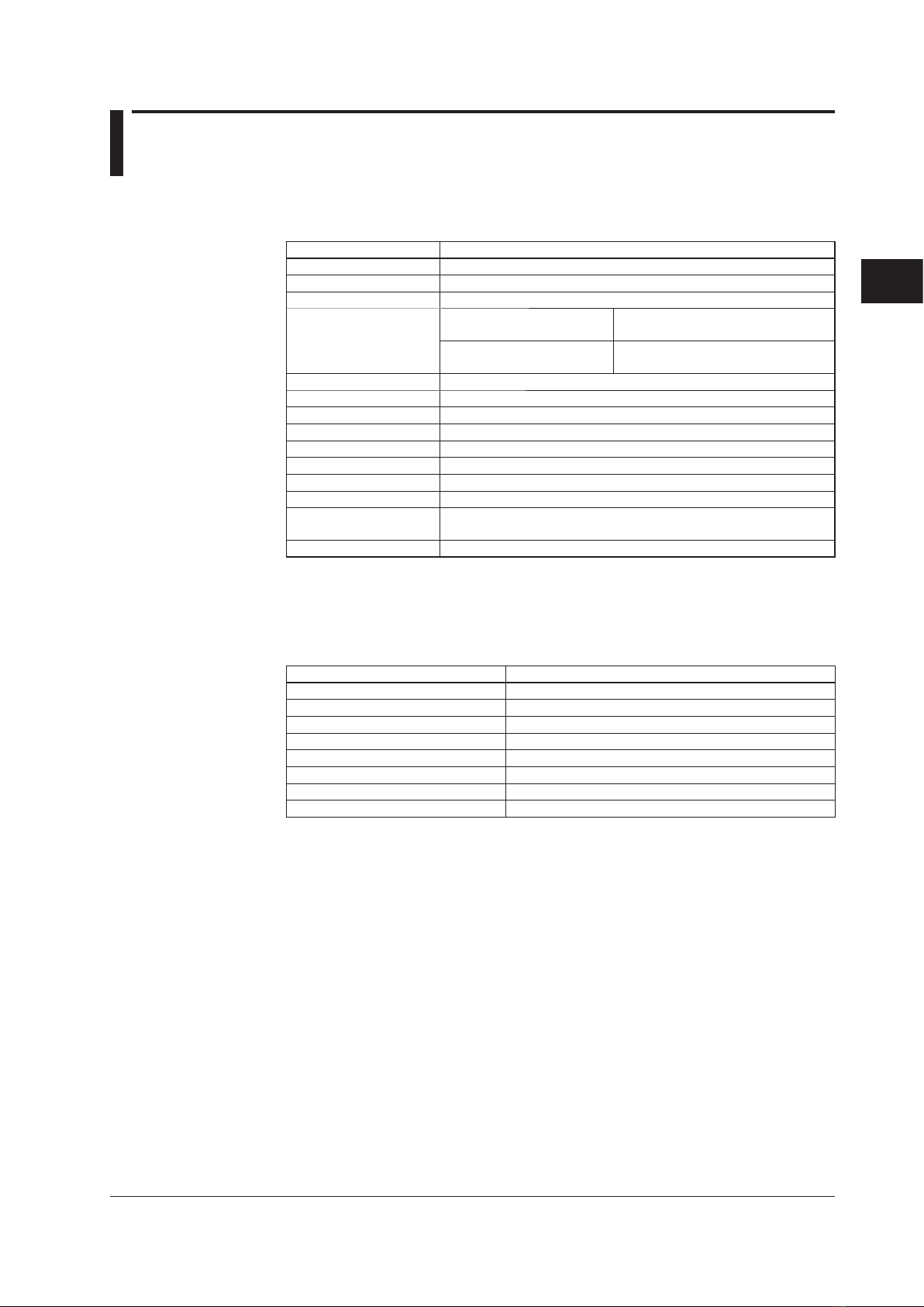
3.4 Test Procedures
Insulation Resistance
● TestProcedures
Perform a measurement with an insulation resistance meter and check whether the
results satisfy the reference values. Perform the measurement with the power switch
turned ON.
Reference Value
Terminals Measured Reference Value Condition
Between the power and protective ground
terminal 100 MΩ or more Short the L (+) and N (–)
terminals.
Between the input and protective ground
terminal 100 MΩ or more Short all input terminals.
Between the Ethernet and protective
ground terminal 100 MΩ or more Short all pins of the Ethernet
terminal.
Between RS-422-A/485 SG and
RS-422-A/485 FG terminals 100 MΩ or more With the /C3 option.
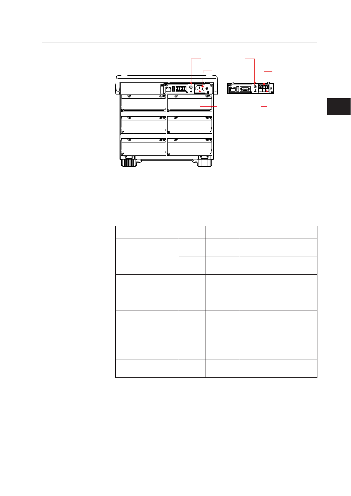
Protective Grounding
● TestProcedures
Perform a resistance measurement with a DMM (digital multimeter), and check
whether the results satisfy the reference values.
Reference Value
Measured Location Reference Value
Between the protective ground terminal
and functional ground terminal 0.2 Ω or less
MV1000
Functional ground
terminal
Power inlet
Protective ground
terminal
Power supply
screw terminals
3-5
SM MV1000-01E
Testing
1
2
3
4
5
6
7
MV2000
Power inlet
Functional ground
terminal
Power supply
screw terminals
Protective ground
terminal
Withstand Voltage
● TestProcedures
Perform the test with a withstanding voltage tester, and check whether the results
satisfy the reference values. Perform the measurement with the power switch turned
ON.
Test time: 1 minute
Tested Terminals Applied
Voltage
Maximum Allowable
Leakage Current
Condition
Between the power and
protective ground terminals
2.3 kVAC 10 mA
For models with 100-240 VAC
power supply.
Short the L and N terminals.
0.5 KVAC 10 mA
For models with 12 VDC power
supply.
Short the + and – terminals.
Between the input and
protective ground terminals 1.5 kVAC 2 mA Short all input terminals.
Between input terminals 1.0 kVAC 1 mA
Short the odd and even channels
of the A/+, B/- terminals*, and
measure between odd and even
channels.
Between relay contact
output and protective
ground terminals
1.6 kVAC 2 mA
With the /A1, /A2, /A3, /A4, or
/F1 option. Short all relay contact
output terminals.
Between the remote control
input and protective ground
terminals
1.0 kVDC 2 mA With the /R1 option. Short all
remote control input terminals.
Between pulse input and
protective ground terminals 1.0 kVDC 2 mA With the /PM1 option. Short all
pulse input terminals.
Between 24 V transmitter
power supply output and
protective ground terminals
500 VAC 10 mA
With the /TPS2 or /TPS4 option.
Short all 24 V transmitter power
supply output terminals.
*The b terminals on the following models are independent on all channels. Short the odd
and even channels of the A/+, B/-, and b terminals, and measure between odd and even
channels.
•MV1004, MV1008, MV2008
• With the /N1 or /N2 option.
3.4 Test Procedures
Other manuals for MVAdvanced MV1000
1
This manual suits for next models
1
Table of contents
Other YOKOGAWA Laboratory Equipment manuals


Popular Laboratory Equipment manuals by other brands


Biotech
Biotech Sequence Precision Series instruction manual

Energenics
Energenics UV-MAX ECO user guide

Techne
Techne TC-PLUS Operator's manual

BANDELIN
BANDELIN Sonorex Digiplus DL 102 H Instructions for use

VWR
VWR VWR Mega Star 600R Service manual

Thermo Electron
Thermo Electron Thermo Spectra-Tech Collector II user manual


