YOKOGAWA PBDH1000 User manual

User’s
Manual Model 701924
PBDH1000 Dierential Probe
IM 701924-01E
6th Edition
User Registration
YOKOGAWA provides registered users with useful information and services. Please
allow us to serve you best by completing the user registration form accessible from
our website.
https://tmi.yokogawa.com/support/
Contact Us
If you want to resolve a technical support issue or need to contact YOKOGAWA,
please fill out the inquiry form on our website.
https://tmi.yokogawa.com/contact/
PIM 103-06E

i
IM 701924-01E
Thank you for purchasing the PBDH1000 Differential Probe (Model 701924).
This user’s manual contains useful information about the functions and
operating procedures of the PBDH1000 Differential Probe and lists the handling
precautions of the instrument. To ensure correct use, please read this manual
thoroughly before beginning operation.
After reading this manual, keep it in a convenient location for quick reference in
the event a question arises during operation.
List of Manuals
The following manuals are provided for the PBDH1000 Differential Probe (Model
701924).
Manual Title Manual No. Notes
Model 701924 PBDH1000
Differential Probe User’s Manual
IM 701924-01E This manual.
Model 701924 PBDH1000
Differential Probe
IM 701924-92 Document for China
Model 701924 PBDH1000
Differential Probe
IM 701924-93Z2 Document for Korea
The “E” and “Z2” in the manual numbers are the language codes.
Contact information of Yokogawa offices worldwide is provided on the following
sheet.
Document No. Description
PIM113-01Z2 List of worldwide contacts
Notes
• The contents of this manual are subject to change without prior notice as
a result of continuing improvements to the instrument’s performance and
functions. The figures given in this manual may differ from those that actually
appear on your screen.
• Every effort has been made in the preparation of this manual to ensure the
accuracy of its contents. However, should you have any questions or find any
errors, please contact your nearest YOKOGAWA dealer.
• Copying or reproducing all or any part of the contents of this manual without
the permission of YOKOGAWA is strictly prohibited.
Revisions
1st Edition: February 2008
2nd Edition: March 2008
3rd Edition: April 2009
4th Edition: November 2015
5th Edition: October 2017
6th Edition: June 2021
6th Edition: June 2021 (YMI)
All Rights Reserved, Copyright © 2008 Yokogawa Electric Corporation
All Rights Reserved, Copyright © 2015 Yokogawa Test & Measurement Corporation
ii IM 701924-01E
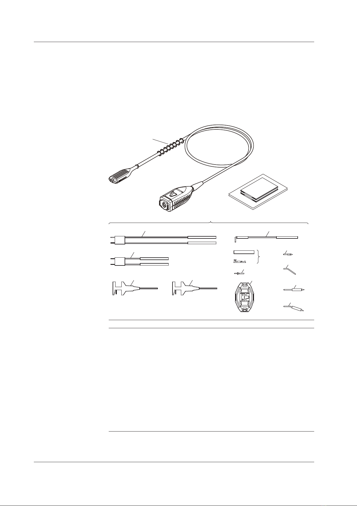
Checking the Contents of the Package
The following accessories are included. If some of the contents are not correct
or missing or if there is physical damage, contact the dealer that you purchased
them from.
• Manuals: 1 set
• Carrying case: 1
• PBDH1000: 1
• Attachments: 1 set
13
12
11
10
9
8
7
6
5
4
3
2
1
Attachments
Name Quantity
1 10-cm pair leads12
2 5-cm pair leads12
3 Red micro clip 1
4 Black micro clip 2
5 6-cm ground extension lead 2
6 Contact, heat-shrink tube1, 2 1 pack (10 pieces)
7 Flanged input pin210
8 Retaining cover22
9 Straight pin 4
10 Angled pin 4
11 Spring-type straight pin 4
12 Spring-type angled pin 4
13 Marker tip38 colors x 1 each
1 Connectable to a 0.64-mm square pin (recommended compatible pin
diameter: 0.65 mm)
2 Extension lead kit
3 Attached to the probe unit.

iii
IM 701924-01E
Checking the Contents of the Package
Optional Accessories (Sold Separately)
Part Name Part Number Quantity
Ground extension lead B8099KQ 5
5-cm pair leads B8099KV 5
10-cm pair leads B8099KU 5
Black micro clip B9852VX 1 pack (10 pieces)
Red micro clip B9852VY 1 pack (8 pieces)
Straight pin B8099DL 10
Angled pin B8099DM 10
Spring-type straight pin B8099DJ 5
Spring-type angled pin B8099DK 5
Flanged input pin B8099KX 5
Retaining cover B8099KY 2
Contact, heat-shrink tube B8099KW 1 pack (10 pieces)

iv IM 701924-01E
Safety Precautions
To ensure safe and correct operation of the instrument, you must take the safety
precautions given on the next page. The instrument may not function if used in
a manner not described in this manual. YOKOGAWA bears no responsibility for,
nor implies any warranty against damages occurring as a result of failure to take
these precautions.
The following safety symbols and words are used in this manual.
Warning: Handle with care. Refer to the user’s manual. This symbol
appears on dangerous locations on the instrument which require special
instructions for proper handling or use. The same symbol appears in the
corresponding place in the manual to identify those instructions.)
Precautions
For safe use of the instrument, and for best results, please heed the following
warnings and cautions.
WARNING
• Take care to avoid electric shock when connecting the probe to the
circuit under test.
• Never disconnect the probe from the measuring instrument while the
probe is connected to the circuit under test.
• Never use the probe with wet hands, or when the probe itself is wet.
Electric shock can result.
• Before connecting the probe input terminal to the circuit under test,
check that the measuring instrument is properly grounded, and that
the probe output connector is connected to the input connector of the
oscilloscope.
• Ground the measuring instrument.
Always connect the main instrument’s protective grounding.
• Observe the maximum non-destructive input voltage.
Do not apply a voltage that exceeds the following values between the
input and ground.
Instantaneous: ±100 V
Continuous: ±35 V (DC + ACpeak)
• Do not use the probe in humid locations
To avoid electric shock, never use the probe in areas of high humidity.
• Do not use the probe near flammable gases.
To avoid injury and fire, do not use the probe near flammable or
explosive gasses or vapors.
• Avoid exposed circuits.
To prevent injury, when the power is ON, do not touch any exposed
contact points or components.

v
IM 701924-01E
Safety Precautions
CAUTION
• The probe head has undergone a precision assembly process. Take
sufficient care when handling the probe as sudden changes in ambient
temperature and physical shocks can damage it.
• Do not inadvertently twist or pull the cable. The wires inside the cable
can break, causing malfunction.
• Avoid vibration, shock, and static electricity during shipping and
handling. Take extra care not to drop the probe.
• Avoid storing or using the probe in direct sunlight, or in areas with high
temperature, humidity, or condensation. Deformation and deterioration
of insulation can occur resulting in failure to retain product specifications.
• Inspect the probe before use to ensure that damage has not occurred
during shipping and storing. If damage is found, contact your nearest
Yokogawa dealer or sales representative.
• This probe is not water or dust resistant. Do not use the probe in areas
with a lot of dust, or near water.
See below for operating environmental limitations.
CAUTION
This product is a Class A (for industrial environments) product. Operation
of this product in a residential area may cause radio interference in which
case the user will be required to correct the interference.

vi IM 701924-01E
Regulations and Sales in Various Countries and Regions
Waste Electrical and Electronic Equipment
(This directive is valid only in the EU.)
This product complies with the WEEE directive marking requirement.
This marking indicates that you must not discard this electrical/
electronic product in domestic household waste.
Product Category
With reference to the equipment types in the WEEE directive, this
product is classified as a “Monitoring and control instruments”
product.
When disposing products in the EU, contact your local Yokogawa
office in Europe. Do not dispose in domestic household waste.
Authorized Representative in the EEA
Yokogawa Europe B.V. is the authorized representative of Yokogawa Test &
Measurement Corporation for this product in the EEA. To contact Yokogawa
Europe B.V., see the separate list of worldwide contacts, PIM 113-01Z2.
Disposal
When disposing of this product, follow the laws and ordinances of your country
or region.
vii
IM 701924-01E
Conventions Used in This Manual
Improper handling or use can lead to injury to the user or
damage to the instrument. This symbol appears on the
instrument to indicate that the user must refer to the user’s
manual for special instructions. The same symbol appears in
the corresponding place in the user’s manual to identify those
instructions. In the manual, the symbol is used in conjunction
with the word “WARNING” or “CAUTION.”
WARNING Calls attention to actions or conditions that could cause serious
injury or death to the user, and precautions that can be taken
to prevent such occurrences.
CAUTION Calls attentions to actions or conditions that could cause light
injury to the user or damage to the instrument or the user’s
data, and precautions that can be taken to prevent such
occurrences.
Note Calls attention to information that is important for proper
operation of the instrument.

viii IM 701924-01E
Contents
List of Manuals................................................................................................................... i
Checking the Contents of the Package............................................................................. ii
Safety Precautions........................................................................................................... iv
Regulations and Sales in Various Countries and Regions............................................... vi
Conventions Used in This Manual .................................................................................. vii
Product Overview..............................................................................................................1
Features............................................................................................................................1
Component Names ...........................................................................................................2
Usage Precautions............................................................................................................3
Operating Procedures.......................................................................................................3
Product Specifications .................................................................................................... 11
Appendix 1 Frequency Characteristics of Each Attachment................................... App-1
Appendix 2 Input Equivalent Circuit and DC Voltage Accuracy.............................. App-4

1
IM 701924-01E
Product Overview
The PBDH1000 Differential Probe is a 1-GHz bandwidth, differential-input,
active probe that is used in combination with a digital oscilloscope that has a
YOKOGAWA probe interface (hereafter referred as digital oscilloscope with a
probe interface).
To use the probe, you simply connect it to a BNC input terminal on a digital
oscilloscope with a probe interface.
* For information about digital oscilloscopes with a probe interface, contact your
nearest YOKOGAWA dealer.
Features
• Allows direct observation of differential signals
• Common mode rejection capability
• Wide frequency bandwidth from DC to 1 GHz
• High input impedance (1 MΩ, approx. 1.1 pF between each input terminal
and ground)
• Able to receive power from a digital oscilloscope with a probe interface
• Allows a digital oscilloscope with a probe interface to automatically detect the
probe*
• Comes with various attachments that can be changed according to the item
that you want to measure
• Compact and lightweight
* For a DL9000 Series digital oscilloscope to automatically detect this probe, the
DL9000 firmware version must be 4.05 or later.
2IM 701924-01E
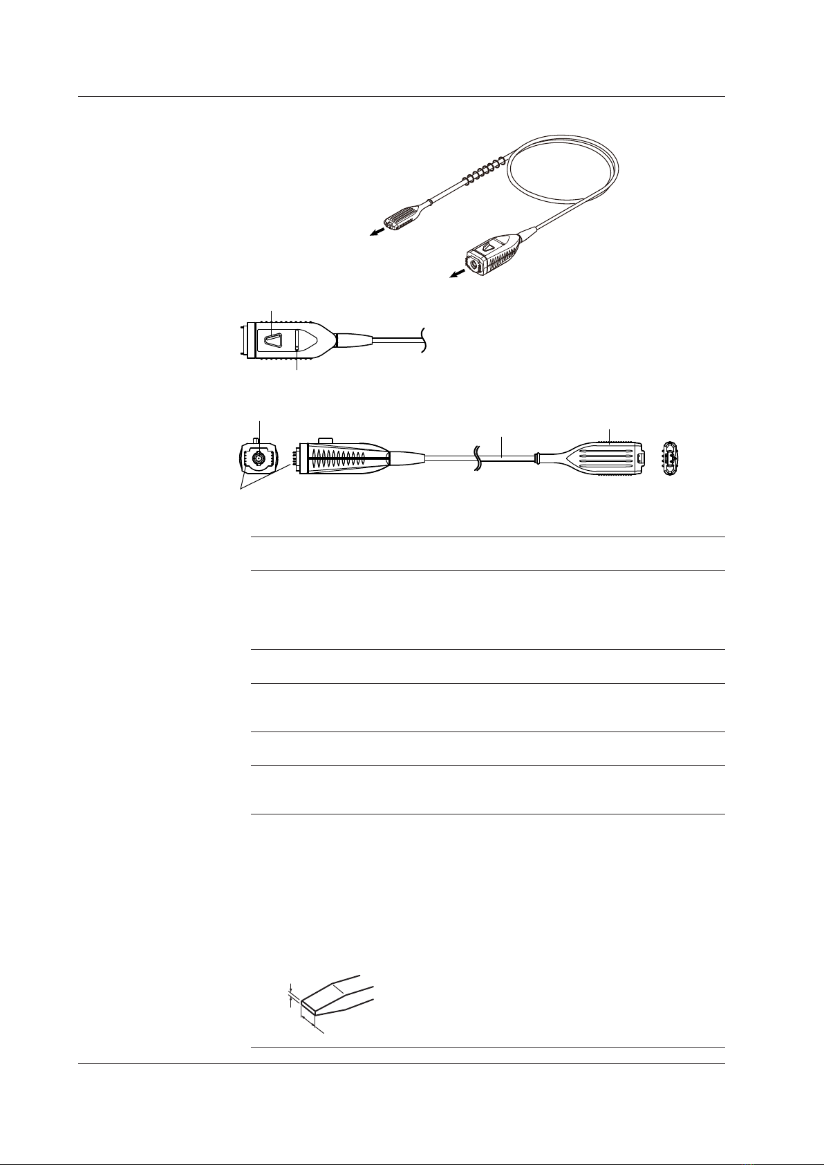
Component Names
Probe head
Cable
Probe interface
Add various
attachments, connect to
circuit under test
To digital oscilloscope input
Latch release lever
Output terminal
Cable Probe head
Interface
spring pin
Variable resistor for adjusting offset voltage
Probe interface
Connects to a digital oscilloscope input.
Interface spring pins
When the probe output terminal is connected, these pins touch the pad on the
oscilloscope interface board. The probe’s power is supplied through these interface
pins. The interface pins are also used to supply a offset voltage and used by the
DL9000 to automatically detect the probe.
Cable
Connects the probe interface and the probe head.
Probe head
Connect various attachments to the signal input terminals, and then connect to the
item you want to measure.
Latch release lever
Releases the lock connecting the probe output terminal to the oscilloscope input.
Output terminal
The output terminal is a BNC connector. It connects to an oscilloscope input BNC
connector.
Variable resistor for adjusting offset voltage
You can adjust the offset voltage using an appropriate driver as described below.
Adjustment driver
Use an adjustment driver that fits into the adjustment groove. Using a driver with
a large grip or a driver with a small head can damage the adjustment turn stop or
groove.
Recommended adjustment driver bit dimensions
Head thickness (W): 0.2 to 0.35 mm; head width (L): 1.3 to 1.5 mm;
head shape: flat or Philips
L
W

3
IM 701924-01E
Usage Precautions
CAUTION
Use a soft cloth to wipe away dirt, and be careful not to damage the probe.
Do not immerse the probe in liquid or use abrasive cleaners on the probe.
Do not use any volatile solvents such as benzine.
Do not bring the probe near transformers, circuits with large currents, wireless
devices, or other objects emitting large electric or magnetic fields. Doing so may
produce inaccurate measurement results.
Operating Procedures
Preparation
1. Have the probe and a digital oscilloscope with a probe interface ready.
2. Insert the probe interface completely into the oscilloscope input, and
confirm that the BNC connector and interface pin are securely fastened.
You will hear the latch click when the connectors lock into place.
3. When you connect the probe to a digital oscilloscope with a probe
interface, the probe’s attenuation ratio and input coupling are set
automatically.*
* For a DL9000 Series digital oscilloscope to automatically detect this probe,
the DL9000 firmware version must be 4.05 or later.
4. Attach any of the provided attachments or attachments that you
constructed to the probe head signal input terminals.
Note
If you are connecting the probe to a DL9000 Series digital oscilloscope with software
version earlier than 4.05, manually configure the following settings after you connect
it.For information on how to update the DL9000 Series software, contact your
nearest YOKOGAWA dealer.
• Set the probe attenuation ratio to 50:1.
• Settheinputcouplingto50Ω.

4IM 701924-01E
Attachment Handling
Connect attachments that are suitable for the item that you want to measure
to the signal input terminals illustrated below. Select attachments from the
following list (see page 9 for attachment application examples).
• 5-cm pair lead
Can connect directly to a pin header or the item you want to measure. It
includes a damping resistor that takes pin header connection into account.
• 10-cm pair lead
Used in combination with a micro clip. It includes a damping resistor that
takes the micro clip into account. It is suitable for measuring relatively low-
frequency signals.
• Pin
The following four types are available. They are suitable for measuring
relatively high-frequency signals.
• Straight pin
• Angled pin
• Spring-type straight pin
• Spring-type angled pin
• A lead that you created using a kit
Create your own lead when you need a lead that is longer than the ones
included in the accessories, or when you want to prevent the lead from
coming loose from the probe head by using the retaining cover. For
instructions on how to create your own lead, see the next page.
Note
• The provided pair leads include the following damping resistors. These pair leads
can connect to a 0.64-mm square pin.
5-cmpairlead: 100Ω,1/4W,1%
10-cmpairlead: 150Ω,1/4W,1%
• For typical frequency characteristics of attachments, see appendix 1.
5.08 mm
Positive signal
input terminal
Negative signal
input terminal
GND terminal
Because the probe input is high impedance, the inductance from the probe
head to the circuit under test has a large effect on the measured results of high
frequency signal components. When measuring signals that include frequency
components of 100 MHz or higher, we recommend that you use the shortest
attachments possible for both the positive and negative input terminals.
Operating Procedures

5
IM 701924-01E
Creating an Extension Lead
You can create your own extension lead using the accessory kit.
At the Circuit-under-Test End
1. Pass the lead wire through a heat-shrink tube for a contact.
2. Crimp or solder the lead wire’s core wire to the contact.
3. Cover the contact with the heat-shrink tube, and then apply heat with a
drier to fix the tube in place.
In step 2, you can insert a damping resistor between the lead wire and contact
as shown in the illustration below on the right.
Contact
<When inserting a resistor>
Resistor
Crimp or solder
Solder
Cover the contact
with a heat-shrink
tube
Solder not allowed*
Crimp or solder
Lead wire (AWG24 to 26 recommended,
maximum diameter: 2.0 mm)
Core wire
Heat-shrink tube for a contact
Lead Wire Length Resistance
Examples of resistances that you can insert
(when using a micro clip)
5 cm 150Ω
10 cm 150Ω
20 cm 180Ω
* If solder gets into this section, the contact or the circuit under test may break.
Note
A dedicated crimping tool is needed to crimp the lead wires (SST-017 by Stack
Electronics Co, Ltd.).
Operating Procedures
6IM 701924-01E
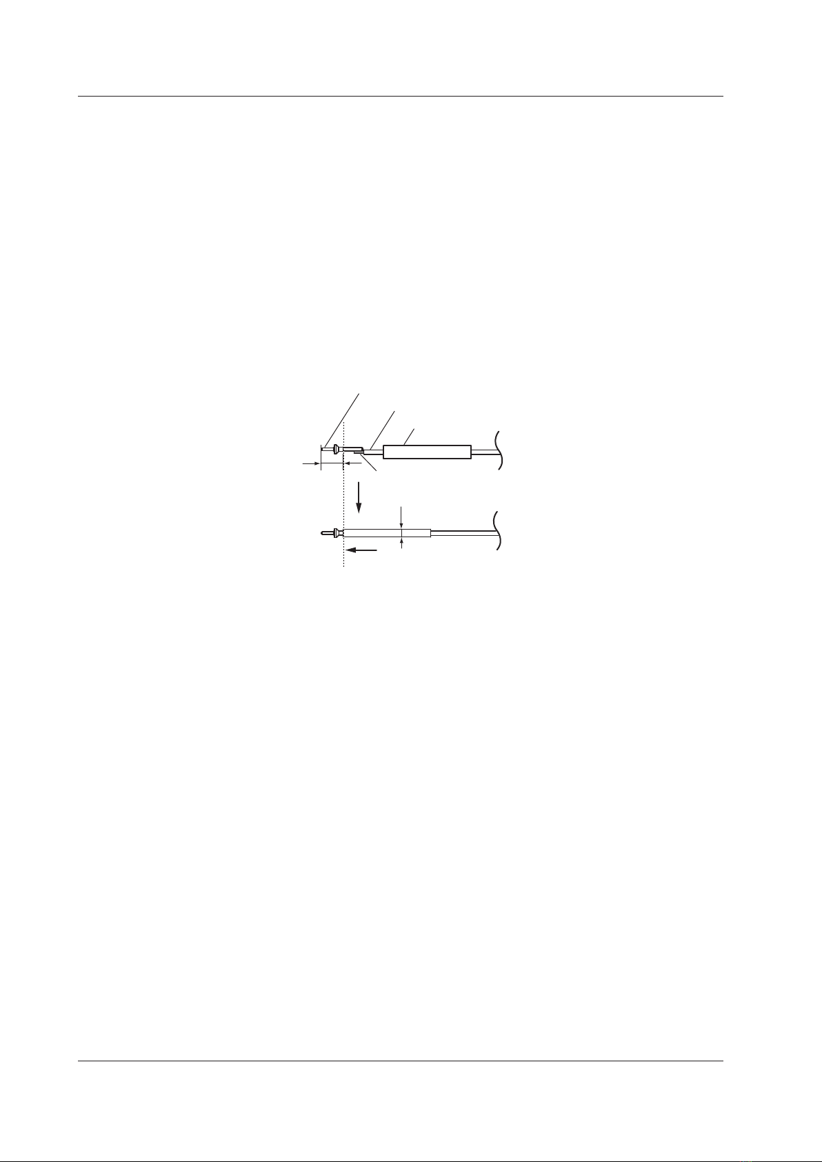
Probe-Head End
4. Pass the lead wire through the heat-shrink tube.
* The heat-shrink tube for the probe-head end is not included. It must be
obtained separately.
5. Solder the lead wire’s core wire to the flanged input pin.
6. Cover the flanged input pin with a heat-shrink tube, and then apply heat
with a drier to fix the tube in place.
Do not cover the section of the flanged input pin to the left of the broken
lines shown in the following figure with the heat-shrink tube. Make sure
that the diameter of the tube after shrinking is 2.0 mm or less. If the
maximum diameter exceeds 2.0 mm, the lead wire will not be able to
pass through the retaining cover.
4.0 mm
(soldering
not allowed*)
φ2.0 mm or less
* If solder gets on this section (4 mm from the tip), the probe may break.
Flanged input pin
Cover with a heat-shrink tube
Solder
Core wire
Lead wire
Heat-shrink tube
Operating Procedures

7
IM 701924-01E
Attaching the Retaining Cover
7. Pass the flanged sections of the two input pins through the center
retaining-cover holes, and place the input pins on the holders on either
side.
Flange
8. Alignthe+and−markingsontheretainingcovertothoseontheprobe
head, and attach the retaining cover to the probe head.
Check that the retaining cover’s left and right latches are securely locked.
Removing the Retaining Cover
9. While pinching the retaining cover at the top and bottom, remove the
cover from the probe head.
Note
• The retaining cover can only be used with a flanged input pin that is included in
the package.
• You cannot use the probe’s ground terminal if you use the retaining cover.
Operating Procedures
8IM 701924-01E
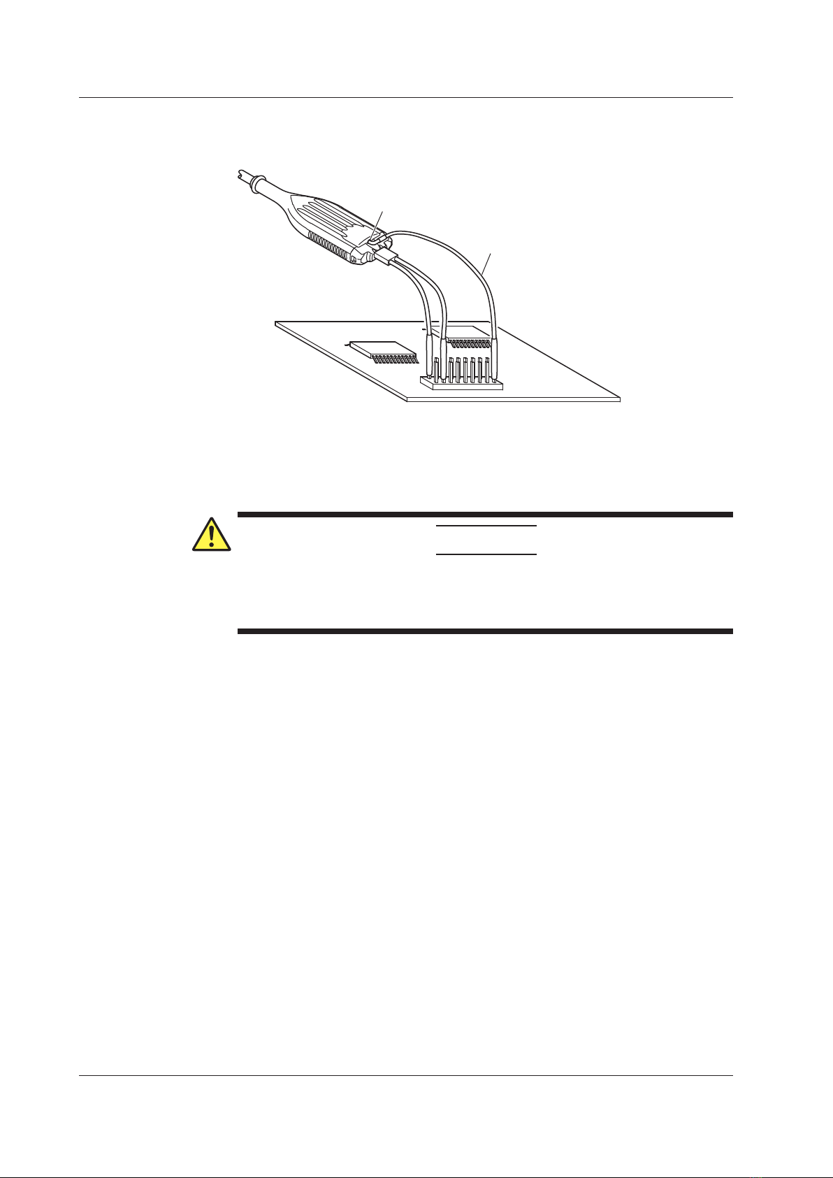
How to Use the Ground Extension Lead
Example
Ground extension lead
Ground terminal
Connecting the probe ground terminal to the common ground on the circuit
under test using the ground extension lead may reduce noise when measuring
low-frequency signals.
CAUTION
Only connect the ground extension lead to the common ground. If you are
measuring a floating circuit, do not use the ground terminal. Doing so may
damage the measuring system or the circuit under test.
Operating Procedures
9
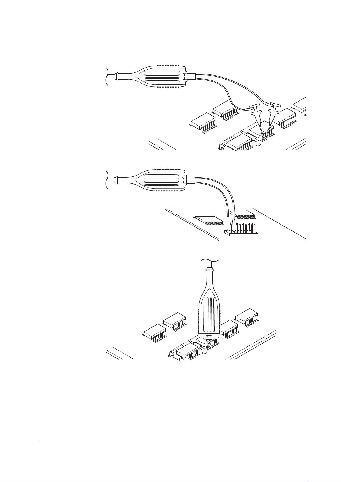
IM 701924-01E
Example
10-cm pair lead with micro chip
5-cm pair lead
Pin (straight, angled, spring-type straight or angled)
Operating Procedures

10 IM 701924-01E
Warm-up and Offset Adjustment
Warm-up
Immediately after connecting the probe, the heat emitted by the probe itself
causes the offset voltage to drift. Warm up the probe for at least 30 minutes
after applying power to stabilize the probe.
Offset Adjustment
You can turn the offset voltage adjustment variable resistor on the probe
interface by using an appropriate adjustment driver (see page 2 for details) to
adjust the residual offset voltage that remains even after warm-up.
CAUTION
Do not turn the variable resistor with excessive force when adjusting the
offset voltage. Doing so may break the variable resistor.
Note
• The offset voltage drifts depending on the ambient temperature. Pay attention to
changes in the ambient temperature when making continuous measurements.
• Only use the offset voltage adjustment variable resistor to adjust the residual
offset voltage. If you deliberately change the offset voltage for some other
purpose, the probe may no longer meet the specifications.
Operating Procedures
Other manuals for PBDH1000
1
This manual suits for next models
1
Table of contents
Other YOKOGAWA Laboratory Equipment manuals


Popular Laboratory Equipment manuals by other brands


Cannon
Cannon CCS-2100 instruction & operation manual

Rainin
Rainin E-Man Hybrid Getting started

Thermo Scientific
Thermo Scientific TSQ 8000 Evo Preinstallation manual

MELAG
MELAG Carebox Blue user manual

Steinberg Systems
Steinberg Systems SBS-LBM-150 user manual

BioNano Genomics
BioNano Genomics Saphyr System Setup guide