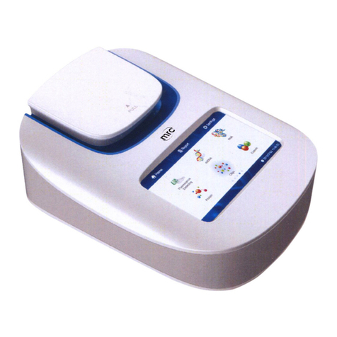
MRC PCR-IF-8C User manual

Operation Manual
PCR-IF-8C
Isothermal Fluorescence PCR
PLEASE READ THIS MANUAL CAREFULLYBEFORE OPERATION
Hagavish st. Israel 58817 Tel: 972 3 5595252, Fax: 972 3 5594529 [email protected]
MRC.2.22

I

I
Foreword
First, Thank you for purchasing our Isothermal Fluorescence PCR.
Before to use the Instrument, please read this manual carefully. In particular, the
highlighted safety knowledge and requirements. This manual describes the
principle, performance, instrument and software operation of the instrument,
simple fault analysis, transportation and storage requirements, etc.
This instrument is non-IVD instrument. It is limited to
scientific research and teaching purposes and shall not
be used in medical diagnosis
Opening check
Please check the instrument and accessories with the packing list when you first
open the packing case. If you find any wrong or missing, please contact the
distributor or the manufacturer.
.Company: MRC CO., LTD

II
Important Guidelines
important safety operation
Please have a comprehensive understanding of how to use before the operation.
Therefore, read this manual carefully before using it.
Any improper operation before reading the manual is forbidden,
otherwise instrument may cause injured or electric shock. Please
read below safety tips and guidelines, and take precautions to
ensure safety.
Using life
See instrument label for details.
Security
The operation, maintenance and repair of the instrument should comply with the
basic guidelines and the remarked warning below. Otherwise, the instrument might
affect the protection provided by the instrument and the intended use of the
instrument.
The instrument conform to classⅠof GB 4793.1 standard. Suggest
use this instrument indoors or outdoors place where avoid light.
Disassemble the instruments without permission is forbidden. This
will make you lose the warranty qualification or have the risk of
electric shock. If repair is needed, please contact the distributor or
the manufacturer.
Make sure the voltage of the power supply is consistent with the
required voltage of the instrument before connecting the power
supply. And make sure the rated load of the power outlet is not less
than required by the instrument.
If the power cord is broken, please replace it with the same type
and specification power cord. Do not cover anything on the
instruments when using. And do not put the power cable in the
place where personnel ambulates.
Insert and pull the power line with hand gently and make sure the
plug completely insert to the jack.

III
The sample holder and heat lid are hot and may cause the scald
when the instrument is working, please make sure the
temperature is cool when you touching them.
The instrument should be kept in a place with low humidity and
dust. Away from water, direct sunlight and strong light source. The
room should be well ventilated, free of corrosive gases or strong
magnetic field interference, away from the heating furnace and
other heating sources.
The air vents on this instrument are designed for ventilation. To
avoid overheating, do not block or cover it. When many
instruments are used at the same time, the distance between each
instrument should be more than 30cm.
Placed the instrument on the horizontal and stable platform where
away from water and dust during the outdoors using. The
instrument should be kept in a cool, clean place and avoid directly
sunlight, strong light to make sure Fluorescence detection can be
used normally.
When using lithium battery, make sure the ambient temperature is
not too high, ambient humidity within allowable range, and in the
place where with less dust and away from water sources (eg:
pool, water pipe).
Power off when you finish the work. Pull off the connector plug
when there’s long time no use of the Instrument and cover it with a
soft cloth or plastic paper to prevent from dust.
Pull the connector plug from the jack at once in the following cases,
and contact the distributor or manufacturer:
There is some liquid flowing into the Instrument, drenched or fire
burned.
Abnormal operation: such as abnormal sound or smell.
Instrument dropping or outer shell damaged. The function has
obviously changed.

IV
Clean the inspection hole and disinfect the instrument with
ultraviolet light before transport please.
Retain the original package for transport using to avoid damage
during transportation.
Warning label
Warning: Hot surface, risk of scald.

V
Contents
Chapter 1 Introduction............................................................................................. 1
Chapter 2 Features....................................................................................................2
Chapter 3 Accessories List........................................................................................ 4
Chapter 4 System structure and accessories........................................................... 5
Chapter 5 Operation Guide...................................................................................... 8
Chapter 6 Fault analysis and solutions...................................................................17
Chapter 7 Maintenance, storage and transportation............................................ 17
Chapter 8 Abbreviations and Tags..........................................................................21

Operation Manual Chapter 1 Introduction
1
Chapter 1 Introduction
PCR-IF-8C Isothermal Fluorescence PCR is contain temperature control block,
fordoptical path detection system, heating lid and analysis software. It is use
d cannisothermal amplification and fluorescence real-time detection of samples, a
s widelyimake quantitative and qualitative analysis of the amplification result. It
i,gused in rapid detection of pathogenic microorganisms(viruses, bacteria, fun
mycoplasma, parasites etc.), food hygiene inspection, environmental monitoring,
sex identification of animal embryos and detection of genetically modified food,
etc.
Working principle:
Temperature control block of the instrument heats the sample seat to heat the
tube in the seat to the needed temperature. The heating lid function can
effectively inhibit the evaporation of reagent and keep the reaction system
constant without adding paraffin oil. The optical path detection system can collect
the fluorescence intensity of the DNA containing dye or probe in the test tube at a
set time interval. The analysis software can process and transform the collected
signals, and finally output the experimental results.
Principle of optical path detection system:
1: Principle diagram of optical path detection system;
21: Plus lens; 22: Excitation filter; 23: Excitation light source
31: Collecting lens; 32: Emission filter; 33: Detector

Operation Manual Chapter 2 Features
2
Chapter 2 Features
2.1. Normal Operating Conditions
Ambient temperature range: 10℃~35℃, Relative humidity range: 20%~75%;
The atmospheric pressure: 860hPa~1060hPa;
Power supply: Input AC 100~240V, 50Hz~60Hz; Output DC15V, 8A;
Ambient: Dry, clean, flat and firm horizontal surface, Away from direct sunlight,
mechanical vibration and strong magnetic field interference.
2.2. Basic Parameters and Performance
Technical
parameters
Product model PCR-IF-8C
Capacity 0.2mL–8wells
(Strip of 8 tubes)
Reaction system 10-150μL
(Recommended 20-30μL)
Power supply/Power Max AC100~240V,50~60Hz/100VA
Dimensions(W*D*H) Max 145*305*100mm
Weight Max 2.5kg
Temperature
control
Heating lid function Yes, temperature is adjustable
Temperature range(℃) 15℃~99℃
Maximum heating rate(℃) ≥2℃/s
Maximum cooling rate(℃) ≥2℃/s
Temperature uniformity(℃) ±0.15℃@39℃
Temperature accuracy/
Control accuracy(℃) ±0.2℃/ 0.1℃
Optical source
Applicable dye FAM/SYBR GreenⅠ, SYTO-16, etc.
Excitation wavelength Ex470nm/LED
Detection wavelength Em535nm/PD
Function
Display 7-inch touch screen
Basic function
Program and sample parameter editing,
fluorescence acquisition, hole negative
positive and peak parameters setting,
normalization function, data management,
data exporting, amplification curve, etc.

Operation Manual Chapter 2 Features
3
Fusion function Analysis of melting curve and melting
peak
Result display mode 1. positive/negative; 2. peak time; 3.
Tm value
Optional software PC software
Software upgrade/Picture
updated U disk upgrade/ U disk updated

Operation Manual Chapter 3 Accessories List
4
Chapter 3 Accessories List
3.1. Standard accessories list
After opening the package, please check each component against the standard
configuration form below and check for missing or damaged.
3.2. Optional list
No. Name Spec/Model Unit Qty Remark
1 Mainframe PCR-IF-8C pcs 1
2 Power cord pcs 1 The plug form is selected
according to the order
3 Power adapter pcs 1
4 Operation manual pcs 1 1 each
5USB flash disk
(contain software) pcs 1 Software included
according to order
requirements
6 USB cable USB2.0-A to B
interface
pcs 1 Selected according to the
included software
7 Warranty card pcs 1
8 Certificate of approval pcs 1
9 Packing list pcs 1
No. Name Spec/Model Unit Qty Remark
1 Thermal printer Outer configuration pcs 1
Optional configuration
for printer
2 Printer USB cable pcs 1
3Printer power
adapter pcs 1
4 Printer paper Φ80*30 pcs 1

Operation Manual Chapter 4 System structure and accessories
5
Chapter 4 System structure and accessories
This chapter mainly introduces the structure of the instrument, kit installation as
well as the preparatory work before starting up. Please have a comprehensive
understanding about the instrument before the first time using.
4.1. Structure
Fig 4.1 Isometric view(Open heating lid)
Fig 4.2 Back view
4.2. Side interface
Fig 4.3 Side interface view

Operation Manual Chapter 4 System structure and accessories
6
4.3. Power adapter
4.4. USB cable, USB flash disk
4.5. Thermal printer
Disclaimer: the above picture is for indication only, subject to actual delivery.

Operation Manual Chapter 4 System structure and accessories
7
4.6. Applicable consumables
4.7. Sample installation
Press the open lid button—The heating lid will open automatically.
Put the reagent tube with the sample in the sample holder, ensure it at the
correct place.
Close the heating lid gently, it will be closed well when listening “click“ sounds.
Fig 4.4 Schematic diagram of sample installation
Notice: The instrument is forbidden to mix centrifugal tubes in one operation
to avoid contamination
No. Specification Applicable situation
1 Non-optical/100ul optical PCR tube ×
2200uloptical PCR tube-Dome top single
tube/Dome top strip of 8 tubes ×
3 200uloptical PCR tube-Flat top single tube √
4 200uloptical PCR tube-Flat top strip of 8 tubes √
5 Tested brand Axygen

Operation Manual Chapter 5 Operation Guide
8
Chapter 5 Operation Guide
5.1. Instrument start
Connect the power adapter, power on switch on the side of the instrument.
The instrument will automatically load the detection system, and the progress
dot on the screen will display the loading progress in real time.
Wait about 1 minute, the screen displays the startup interface and
automatically performs the self-check function. If there are any abnormalities,
there will be a prompt window with a "beep" sound.
Startup initial interface default is: Detection Interface>> Isothermal
amplification
5.2. Fast start experiment
Name Button Description
Test
Store and summarize new
settings or running program
files, read section 5.4.
Data
Store and summarize
experimental data files, read
section 5.5.
Settings
Display menu under the
settings, read section 5.6.
Isothermal
Amp.
Store and summarize program
files about isothermal
amplification, and sort by new
time.
Isothermal
Anneal
Store and summarize program
files about isothermal anneal,
and sort by new time.
Anneal
Detection
Store and summarize program
files about anneal detection,
and sort by new time.
Program
Document
Click it enter the running
interface, the program name
can be changed.
Arrow Display “next”,
“previous”program files.

Operation Manual Chapter 5 Operation Guide
9
5.3 Experiment setup and operation
There are two ways for users to experiment, that are fast start experiment and
new program experiment.
Way 1 Fast start experiment
Way 2 New setting
The prerequisite for this way: The test interface
has successfully stored the program file of the new
setting or the program has been stored and run.
Under the test interface, select the upper program
type: isothermal amplification, isothermal anneal
and anneal detection, click the one you need.
Input the name on the pop up dialog, the name of
the original program file will not change. As shown
in figure.
Click <OK> to enter the running interface.
1)Temperature setting
Click <Test>, <Settings>,<Experiment Setting>
interface.
Select the upper program type: isothermal
amplification, isothermal anneal and anneal
detection. Then click <New> on the lower left
corner and name the program on the pop up
dialog.
Enter setting interface:
Preheat: Open and close (Figure is opening); set
the preheating temperature and time.
Isothermal: set isothermal temperature, time
and measure period. The period ranges from 3
seconds to 30 seconds.
Anneal: Set temperature 1, anneal time,
temperature 2, rate and measure period. When
the isothermal anneal and anneal detection is
selected.

Operation Manual Chapter 5 Operation Guide
10
Click , enter the advanced interface.
5) Sample name change
Click the name to edit, for example: The well 1 defaults to "Sample 1", which can be
changed to "Prawn". Then click icon to back and store the new program. And enter
<Test> interface, choose the edited program to enter <Run> interface.
2) Negative and positive setting
Click the default peak judgment blue button to set
result judgment.
Del button, cancel the judgment.
Add button, add the judgment, and set the time, can
combine a variety of results. But the most result is
three: Positive, weak positive and negative judgment.
3) Select channel
Select the appropriate experimental channel according
to the reagent dye wavelength, Channel 1: FAM, SYBR
GreenⅠ...
4) Setting of peak/head time parameters
The peak time Tt of the amplification curve is related to
three parameters, the relationship between the three
parameters is "and".
PN Factor(Positive&Negative coefficient) can set range
0.001~0.255, the default is 0.02. It is understood that
the well exists the "S" type amplification curve which is
one of the conditions for calculating the head time.
Tt Factor(Time threshold coefficient)can set range
0.001~0.255, the default is 0.02. And TtFactor≤PN Factor.
PN limit(Positive&Negative limit)can set range
200~30000, the default is 10000, refers to the difference
between the fluorescence intensity at baseline and the
fluorescence intensity at plateau, is one of the
conditions to calculate head time.

Operation Manual Chapter 5 Operation Guide
11
5.4. Program Running
The program interface has five function interfaces: Running program, real-time
temperature, amplification curve, anneal curve and results. In order to facilitate
the user to view the data during the experiment, the switch operation can be
carried out quickly.
Note: Channel 2 is under development. At present, this model has only
channel 1. If you have any needs, please contact our company.
1) Program interface
The parameter of the running program can be viewed,
as the left picture, for example: preheating Temp.,
Time, Measure period, etc. But can not be changed.
The selected channel conditions and peak time
settings, negative and positive settings can be viewed
in real-time.
The real-time sample holder temperature, progress bar,
remaining time and total experimental time are displayed
at the bottom of the interface.
2) Real-time temperature
It will display the temperature curves of heating lid and
sample holder. The temperature curves of heating lid
need manually opened in the background. The
x-coordinate is time(Unit: min) and the y-coordinate is
temperature(Unit:℃).
During the experiment, if need increase/extend the
experiment time. Can click <+3 Minute>, <+5 Minute>,
<+10 Minute> and can cumulative increase. After the
addition, the negative and positive determination
conditions and the program files will not be changed,
only this experimental program will be stored.

Operation Manual Chapter 5 Operation Guide
12
3) Amplification curve
It used to display the reagent amplification curves
during the experiment in real time. The x-coordinate is
time(Unit: min) and the y-coordinate is fluorescence
intensity. Coordinate will be adjusted automatically.
<Normalized> button, all reagent curves will be
"normalized", that is, the baseline of all curves will be
normalized.
Click the colored circular button below to display or
hide the reagent curve of the hole. Click < Null > and all
curves will be hidden.
Note: The hole color can be set in <color>, read section
5.6.
4) Anneal curve
It is used to display anneal curves in real time
which is divided into fluorescence curve and
derivative curve.
Fluorescence curve: The x-coordinate is
temperature(℃) and the y-coordinate is fluorescence
intensity.
Derivative curve: The x-coordinate is temperature(℃)
and the y-coordinate is derivative.
5) Results
Review the result data, contain results, Amp. Time,
peak value temperature, etc.
Export data to USB flash disk and print.
Note: Print options need to be connected to an
external thermal printer. Read section 3.2 optional list.

Operation Manual Chapter 5 Operation Guide
13
5.5 Datareview and management
Click the <Data> interface on the right of <Test>. Rules for data storage: 1) Type of
program file, which is classification. 2) Sort the data files in reverse order according
to the time they have been saved, which is time sort.
Note: The old version of the software is based on the year/month/day to classify
and store the data file.
It need to point out that the content of <Data> and <Running> interface is
basically the same, the difference is that in <Data> interface the parameters
of peak time and negative and positive can be edited, and the corresponding
results will be updated.
Data save as
Data files saved format: File name and saved time
Data manage
Click <manage> on the top right corner to cancel
or send the data files. Click <close> to exit the
manage interface.
Data view
Click the data file you want to view to enter the
data file interface. Read section 5.4 <Running>
interface.
Click back to the previous interface.
Users can click the to page up and down.
Edit peak time parameters
Read <Setting of peak/head time parameters> in <5.3
Experiment setup and operation>.
Edit negative and positive parameters
Read <Negative and positive setting> in <5.3
Experiment setup and operation>
Table of contents
Other MRC Laboratory Equipment manuals
Popular Laboratory Equipment manuals by other brands

IKA
IKA Roller 6 digital operating instructions

Pecon
Pecon P Lab-tek Series manual

Environmental Express
Environmental Express LE1003 Operation manual

TriContinent
TriContinent MULTIWASH III Operation and maintenance manual

Metrohm
Metrohm Eco KF Titrator Product information

Labconco
Labconco CApture 3420000 user manual

Malvern Instruments
Malvern Instruments ZETASIZER Basic guide

Agilent Technologies
Agilent Technologies PR02 Operation manual

diapath
diapath Galileo SEMI user manual

KaVo
KaVo QUATTROcare PLUS 2124 A Instructions for use

Labnet
Labnet Excel P3600L-10 quick start guide

Thermo Scientific
Thermo Scientific Omni FTIR Multi Gas CEMS instruction manual