GMI D5015SS User manual

D5015 - SIL 2 Repeater Power Supply G.M. International ISM0397-3
SIL 2 Repeater Power Supply Hart,
DIN-Rail and Termination Board
Models D5015SS, D5015SK
D5015SS - D5015SK
INSTRUCTION MANUAL

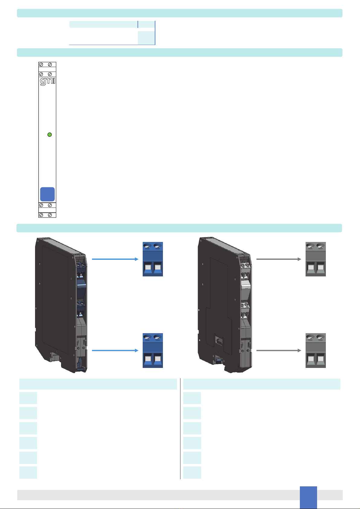
2 D5015 - SIL 2 Repeater Power Supply G.M. International ISM0397-3
General Description:
The single channel Repeater Power Supply, D5015SS and D5015SK modules, is a high integrity analog input interface suitable for applications requiring SIL 2 level (according to IEC
61508:2010 Ed.2) in safety related systems for high risk industries.
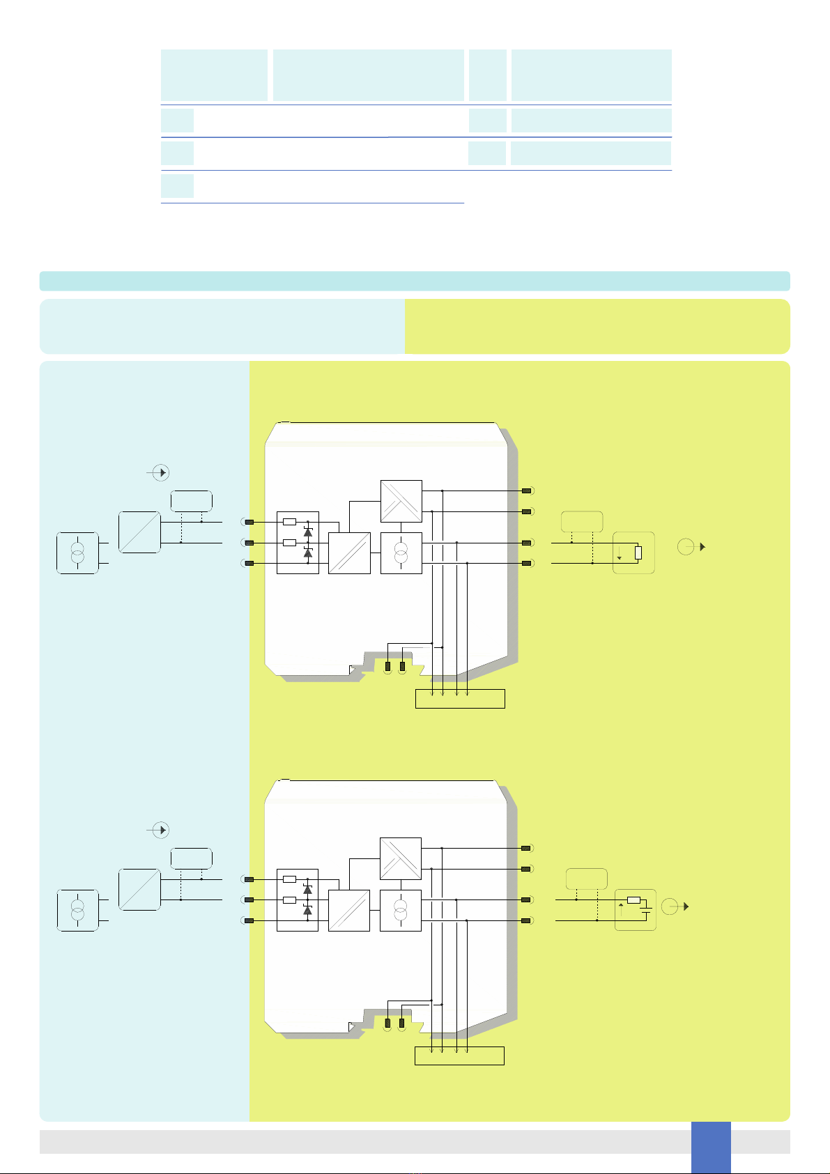
Provides a fully floating dc supply for energizing conventional 2 wires passive 4-20 mA or 4 wires (active) transmitters located in Hazardous Area, and repeats the current in floating
circuit to drive a Safe Area load. The circuit allows bi-directional communication signals, for HART® transmitters.
Mounting on standard DIN-Rail, with or without Power Bus, or on customized Termination Boards, in Safe Area / Non Hazardous Location or in Zone 2 / Class I, Division 2 or Class I,
Zone 2.
D5015SS: Single channel, source output.
D5015SK: Single channel, sink output.
Functional Safety Management Certification:
G.M. International is certified by TUV to conform to IEC61508:2010
part 1 clauses 5-6 for safety related systems up to and included SIL 3.
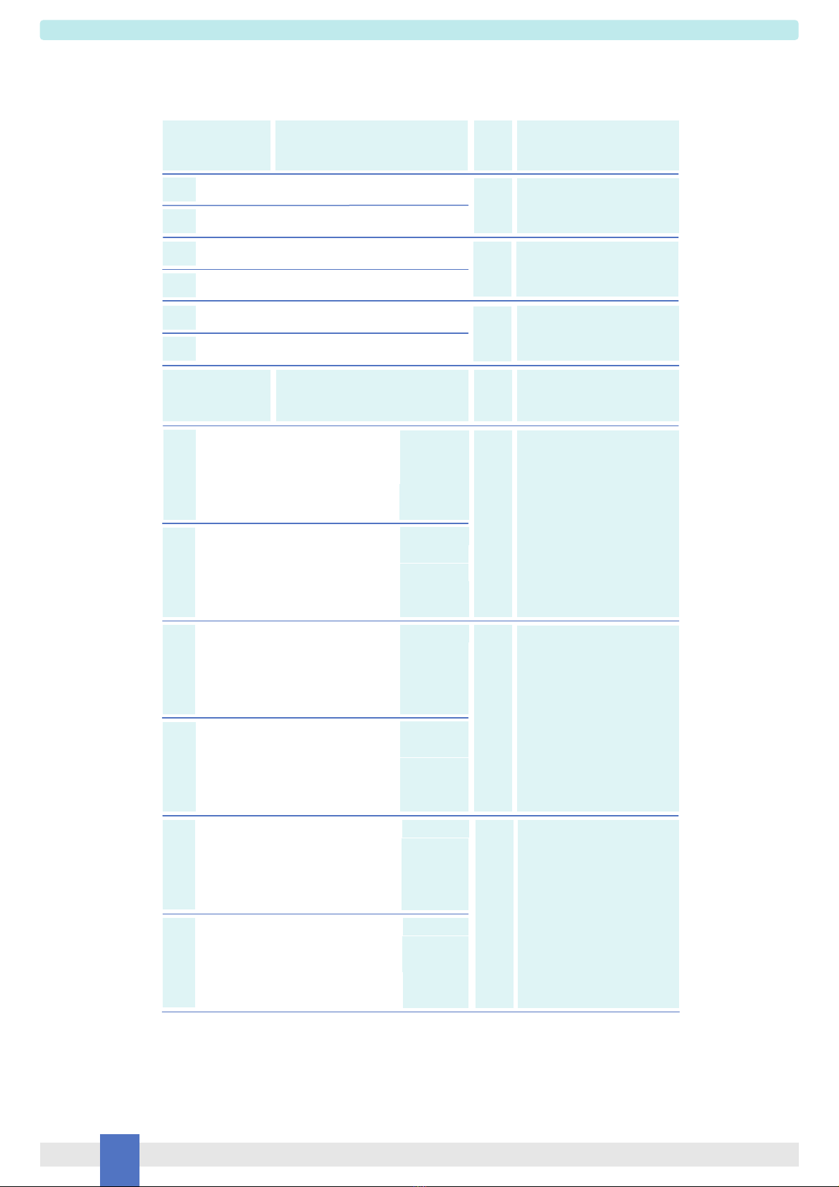
Technical Data
Characteristics
Supply:
24 Vdc nom (18 to 30 Vdc) reverse polarity protected, ripple within voltage limits 5 Vpp, 2 A time lag fuse internally protected.
Current consumption @ 24 V: 50 mA with 20 mA output typical.
Power dissipation: 0.90 W with 24 V supply voltage and 20 mA output typical.
Isolation (Test Voltage):
I.S. In/Out 2.5 KV; I.S. In/Supply 2.5 KV; Out/Supply 500 V.
Input:
4 to 20 mA (separately powered input, voltage drop 0.5 V) or
4 to 20 mA (2 wires Tx current limited at 25 mA), reading range 0 to 24 mA.
Transmitter line voltage:
16.0 V typical at 20 mA with max.
Output:
4 to 20 mA, on max. 550 load in source mode (typical 12 V compliance);
V min. 8 V at 0 load V max. 30 V in sink mode, current limited at 25 mA.
Response time: 5 ms (0 to 100 % step change).
Performance:
Ref. Conditions 24 V supply, 250 load, 23 ± 1 °C ambient temperature.
Calibration accuracy: ± 0.1 % of full scale.
Linearity error: ± 0.05 % of full scale.
Supply voltage influence: ± 0.02 % of full scale for a min to max supply change.
Load influence: ± 0.02 % of full scale for a 0 to 100 % load resistance change.
Temperature influence: ± 0.01 % of full scale on zero and span for a 1°C change.
Compatibility:
CE mark compliant, conforms to Directives:
2014/34/EU ATEX, 2014/30/EU EMC, 2014/35/EU LVD, 2011/65/EU RoHS.
Environmental conditions:
Operating: temperature limits – 40 to + 70 °C, relative humidity 95 %, up to 55 °C.
Max altitude: 2000 m a.s.l.
Storage: temperature limits – 45 to + 80 °C.
Safety Description:
ATEX: II 3(1) G Ex ec [ia Ga] IIC T4 Gc, II (1) D [Ex ia Da] IIIC, I (M1) [Ex ia Ma] I
IECEx: Ex ec [ia Ga] IIC T4 Gc, [Ex ia Da] IIIC, [Ex ia Ma] I
UL: NI / I / 2 / ABCD / T4, AIS / I, II, III / 1 / ABCDEFG, AEx nA [ia Ga] IIC T4 Gc; C-UL: NI / I / 2 / ABCD / T4, AIS / I, II, III / 1 / ABCDEFG, Ex nA [ia Ga] IIC T4 Gc X
associated apparatus and non-sparking electrical equipment.
Uo/Voc = 26.8 V, Io/Isc = 92 mA, Po/Po = 614 mW at terminals 7-8,
Uo/Voc = 1.1 V, Io/Isc = 56 mA, Po/Po = 16 mW at terminals 8-11,
Ui/Vmax = 30 V, Ii/Imax = 128 mA, Ci = 0 nF, Li = 0 nH at terminals 8-11,
Um = 250 Vrms or Vdc, -40 °C Ta 70 °C.
Approvals:
BVS 20 ATEX E 023 X conforms to EN60079-0, EN60079-11, EN60079-7.
IECEx BVS 20.0016X conforms to IEC60079-0, IEC60079-11, IEC60079-7.
UL & C-UL E222308 conforms to UL 61010-1, UL913, UL 60079-0, UL60079-11, UL60079-15, UL121201 for UL
and CAN/CSA C22.2 No. 61010-1-12, CSA-E60079-0, CSA-E60079-11, CSA-E60079-15 and CSA-C22.2 No. 213 for C-UL.
TUV Certificate No. C-IS-272994-01 SIL 2 conforms to IEC61508:2010 Ed. 2.
TÜV Certificate No. C-IS-236198-09, SIL 3 Functional Safety Certificate conforms to IEC61508:2010 Ed.2, for Management of Functional Safety.
Mounting:
EN/IEC60715 TH 35 DIN-Rail, with or without Power Bus or on customized Termination Board.
Weight: about 130 g.
Connection: by polarized plug-in disconnect screw terminal blocks to accommodate terminations up to 2.5 mm2(13 AWG).
Location: installation in Safe Area/Non Hazardous Locations or Zone 2, Group IIC T4 or Class I, Division 2, Group A,B,C,D, T4 or Class I, Zone 2, Group IIC, T4.
Protection class: IP 20.
Dimensions: Width 12.5 mm, Depth 123 mm, Height 120 mm.
FSM
SIL 3

3
D5015 - SIL 2 Repeater Power SupplyG.M. International ISM0397-3
Ordering Information
Front Panel and Features
SIL 2 (low demand mode of operation) according to IEC 61508:2010 Ed.2 with Tproof = 13 / 20 yrs (10 / >10 % of total SIF).
SC3: Systematic capability SIL 3.
Input from Zone 0 / Division 1.
Installation in Zone 2 / Division 2.
4-20 mA Input Signal Active-Passive.
4-20 mA Output Signal Source-Sink.
HART® compatible.
Input and Output short circuit proof.
High Accuracy.
Three port isolation, Input/Output/Supply.
EMC Compatibility to EN61000-6-2, EN61000-6-4, EN61326-1, EN61326-3-1 for safety systems.
ATEX, IECEx, UL & C-UL, TÜV Certification.
TÜV Functional Safety Certification.
Simplified installation using standard DIN-Rail and plug-in terminal blocks, with or without Power Bus, or customized Termination
Boards.
250 Vrms (Um) max. voltage allowed to the instruments associated with the barrier.
+ Input Ch 1 for 2 wires Transmitters
Terminal block connections
HAZARDOUS AREA SAFE AREA
- Input Ch 1 for 2 wires Transmitters or
+ Input Ch 1 for External Powered Transmitters
-
-
- Input Ch 1 for External Powered Transmitters
-
7
8
9
10
11
12
+ Output Ch 1
1
- Output Ch 1
2
-
3
-
4
+ Power Supply 24 Vdc
5
- Power Supply 24 Vdc
6
Model: D5015
1 channel source output SS
1 channel sink output SK
Power Bus and DIN-Rail accessories:
Connector JDFT049 Cover and fix MCHP196
Terminal block male MOR017 Terminal block female MOR022
7 8
11 12
12
56
11
D5015
12
7 8
1 2
5 6
SIL 2
1
PWR

4 D5015 - SIL 2 Repeater Power Supply G.M. International ISM0397-3
Parameters Table
Must
be
Hazardous Area/
Hazardous Locations
Device Parameters
D5015 Associated
Apparatus Parameters
Must
be
Hazardous Area/
Hazardous Locations
Device + Cable Parameters
Uo / Voc = 26.8 V
Ui / Vmax
In the system safety analysis, always check the Hazardous Area/Hazardous Locations devices to conform with the related system documentation, if the device is Intrinsically Safe check
its suitability for the Hazardous Area/Hazardous Locations and group encountered and that its maximum allowable voltage, current, power (Ui/Vmax, Ii/Imax, Pi/Pi) are not exceeded
by the safety parameters (Uo/Voc, Io/Isc, Po/Po) of the D5014 series Associated Apparatus connected to it. Also consider the maximum operating temperature of the field device,
check that added connecting cable and field device capacitance and inductance do not exceed the limits (Co/Ca, Lo/La, Lo/Ro) given in the Associated Apparatus parameters for the
effective group. See parameters indicated in the table below:
D5015 Terminals
Ch1 7 - 8
Uo / Voc = 1.1 V
Ch1 8 - 11
Io / Isc = 92 mACh1 7 - 8
Io / Isc = 56 mA
Ch1 8 - 11
Po / Po = 614 mW
Ch1 7 - 8
Po / Po = 16 mW
Ch1 8 - 11
Ii/ Imax
Pi / Pi
D5015 Terminals
Ch1 8 - 11
D5015 Associated Apparatus
Parameters Cenelec (US)
Ci / Ci device + C cable
IIC (A, B)
Co / Ca = 92 nF
Co / Ca = 720 nF
Co / Ca = 2.37 µF
IIB (C)
IIA (D)
IIC (A, B)
Co / Ca = 100 µF
Co / Ca = 1000 µF
Co / Ca = 1000 µF
IIB (C)
IIA (D)
Co / Ca = 4.2 µF
Co / Ca = 720 nF
I
IIIC (E, F, G)
I
Co / Ca = 1000 µF
Co / Ca = 1000 µF
Ch1 7 - 8
Ch1 8 - 11
Li / Li device + L cable
IIC (A, B)
Lo / La = 4.2 mH
Lo / La = 16.9 mH
Lo / La = 33.8 mH
IIB (C)
IIA (D)
IIC (A, B)
Lo / La = 11.5 mH
Lo / La = 46 mH
Lo / La = 92.1 mH
IIB (C)
IIA (D)
Lo / La = 55.4 mH
Lo / La = 16.9 mH
I
IIIC (E, F, G)
I
Lo / La = 151.2 mH
Lo / La = 46 mH
Ch1 7 - 8
Ch1 8 - 11
Li / Ri device and
L cable / R cable
IIC (A, B)
Lo / Ro = 57.9 µH/
Lo / Ro = 231.6 µH/
Lo / Ro = 463.3 µH/
IIB (C)
IIA (D)
IIC (A, B)
Lo / Ro = 2327.2 µH/
Lo / Ro = 9309 µH/IIB (C)
IIA (D)
Lo / Ro = 760.1 µH/
Lo / Ro = 231.6 µH/
I
IIIC (E, F, G)
I
IIIC (E, F, G)
Lo / Ro = 30545.4 µH/
Lo / Ro = 9309 µH/
Ch1 7 - 8
Lo / Ro = 18618.1 µH/
IIIC (E, F, G)
IIIC (E, F, G)

5
D5015 - SIL 2 Repeater Power SupplyG.M. International ISM0397-3
When used with separate powered intrinsically safe devices, check that maximum allowable voltage, current (Ui/Vmax, Ii/Imax) of the D5014 Associated Apparatus are not exceeded by
the safety parameters (Uo/Voc, Io/Isc) of the Intrinsically Safe device, indicated in the table below:
For installations in which both the Ci and Li of the Intrinsically Safe apparatus exceed 1% of the Co and Lo parameters of the Associated Apparatus (excluding the cable),
then 50% of Co and Lo parameters are applicable and shall not be exceeded (50% of the Co and Lo become the limits which must include the cable such that Ci device + C cable
50 % of Co and Li device + L cable 50 % of Lo). The reduced capacitance of the external circuit (including cable) shall not be greater than 1 F for Groups I, IIA, IIB and 600 nF for
Group IIC. If the cable parameters are unknown, the following value may be used: Capacitance 200 pF per meter (60 pF per foot), Inductance 1 µH per meter (0.20 µH per foot).
Must
be
Hazardous Area/
Hazardous Locations
Device Parameters
D5015 Associated
Apparatus Parameters
Ui / Vmax = 30 V Uo / Voc
D5015 Terminals
Ch1 8 - 11
li / Imax = 128 mA
Ch1 8 - 11
Io / Isc
Ci = 0 nF, Li= 0 nH
Ch1 8 - 11
Function Diagram
HAZARDOUS AREA ZONE 0 (ZONE 20) GROUP IIC,
HAZARDOUS LOCATIONS CLASS I, DIVISION 1, GROUPS A, B, C, D,
CLASS II, DIVISION 1, GROUPS E, F, G, CLASS III, DIVISION 1,
CLASS I, ZONE 0, GROUP IIC
SAFE AREA, ZONE 2 GROUP IIC T4,
NON HAZARDOUS LOCATIONS, CLASS I, DIVISION 2,
GROUPS A, B, C, D T-Code T4, CLASS I, ZONE 2, GROUP IIC T4
==
=
5 +
6 -
1
2RLmA
+
-
HHT Source I
Out (SIL 2)
Supply 24 Vdc
7
11
+
-
HHT
2 Wire Tx
I
?
+
-
External
Powered Tx
In
8
MODEL D5015SS
=
=
+
-Termination
board
connector
Power Bus
==
=
5 +
6 -
1
2Out (SIL 2)
Supply 24 Vdc
7
11
+
-
HHT
2 Wire Tx
I
?
+
-
External
Powered Tx
In
8
MODEL D5015SK
=
=
+
-Termination
board
connector
Power Bus
mA +
Sink I
+
-
RL
HHT

6 D5015 - SIL 2 Repeater Power Supply G.M. International ISM0397-3
D5015 series are isolated Intrinsically Safe Associated Apparatus installed into standard EN/IEC60715 TH 35 DIN-Rail located in Safe Area or Zone 2, Group IIC, Temperature T4 or
Class I, Division 2, Group A, B, C, D, T4 Hazardous Area within the specified operating temperature limits Tamb -40 to +70 °C, and connected to equipment with a maximum limit for
power supply Um of 250 Vrms or Vdc.
Not to be connected to control equipment that uses or generates more than 250 Vrms or Vdc with respect to earth ground.
D5015 series must be installed, operated and maintained only by qualified personnel, in accordance to the relevant national/international installation standards (e.g. EN/IEC60079-14
Electrical apparatus for explosive gas atmospheres - Part 14: Electrical installations in hazardous areas (other than mines)), following the established installation rules, particular care
shall be given to segregation and clear identification of I.S. conductors from non I.S. ones.
De-energize power source (turn off power supply voltage) before plug or unplug the terminal blocks when installed in Hazardous Area or unless area is known to be nonhazardous.
Warning: substitution of components may impair Intrinsic Safety and suitability for Zone 2.
Explosion Hazard: to prevent ignition of flammable atmospheres, disconnect power before servicing or unless area is known to be nonhazardous.
Failure to properly installation or use of the equipment may risk to damage the unit or severe personal injury.
The unit cannot be repaired by the end user and must be returned to the manufacturer or his authorized representative. Any unauthorized modification must be avoided.
Warning
Operation
D5015 provides fully floating DC supply for energizing 2 wires 4-20 mA transmitters, or separately powered 4 wires, 4-20 mA transmitters located in Hazardous Area and repeats the
current to a 4-20 mA floating output signal to drive a Safe Area load.
The circuit allows bi-directional communication signal for smart transmitters, a “POWER ON” green led for each channel lits when input power is present.
Installation
D5015 series are Repeater power supply HART® compatible housed in a plastic enclosure suitable for installation on EN/IEC60715 TH 35 DIN-Rail, with or without Power Bus or on
customized Termination Board. D5015 series can be mounted with any orientation over the entire ambient temperature range.
Electrical connections are accommodated by polarized plug-in removable screw terminal blocks which can be plugged in/out into a powered unit without suffering or causing any damage
(for Zone 2 installations check the area to be nonhazardous before servicing). Connect only one individual conductor per each clamping point, use conductors up to 2.5 mm²
(13 AWG) and a torque value of 0.5-0.6 Nm. Use only cables that are suitable for a temperature of at least 85°C.The wiring cables have to be proportionate in base to the current and the
length of the cable.
In case of installation in zone 2, the connecting cables of non-intrinsically safe circuits must be safely routed in a cable duct or similar. The distance between the pluggable connection
terminal and the cable duct should not exceed 500 mm cable length.
On the section “Function Diagram” and enclosure side a block diagram identifies all connections.
Intrinsically Safe conductors must be identified and segregated from non I.S. and wired in accordance to the relevant national/international installation standards (e.g. EN/IEC60079-14
Electrical apparatus for explosive gas atmospheres -Part 14: Electrical installations in hazardous areas (other than mines)), make sure that conductors are well isolated from each other
and do not produce any unintentional connection. Isolation in accordance with EN/IEC 60079-11 clause 6.3.13 is provided between non-intrinsically safe circuits and intrinsically safe
circuits.
The enclosure provides, according to EN60529, an IP20 minimum degree of protection (or similar to NEMA Standard 250 type 1). The unit shall be installed in an area of no more than
pollution degree 2 according to EN/IEC60664-1. When installed in EU Zone 2, the unit shall be mounted in a certified Ex enclosure that provides a degree of protection not less than IP54
in accordance with EN/IEC60079-15. When installed in a Class I, Zone 2 Hazardous Location, the unit shall be mounted in a supplemental AEx or Ex enclosure that provides a degree of
protection not less than IP54 in accordance with UL/CSA 60079-15. When installed in a Class I, Division 2 Hazardous Location, the unit shall be mounted in a supplemental enclosure
that provides a degree of protection not less than IP54. The enclosure must have a door or cover accessible only by the use of a tool. The end user is responsible to ensure that the
operating temperature of the module is not exceeded in the end use application.
Units must be protected against dirt, dust, extreme mechanical (e.g. vibration, impact and shock) and thermal stress, and casual contacts. If enclosure needs to be cleaned use only a
cloth lightly moistened by a mixture of detergent in water.
Electrostatic Hazard: to avoid electrostatic hazard, the enclosure of D5015 series must be cleaned only with a damp or antistatic cloth.
Any penetration of cleaning liquid must be avoided to prevent damage to the unit.
Any unauthorized modification must be avoided.
D5015 series must be connected to SELV or PELV supplies.
All circuits connected to D5015 series must comply with the overvoltage category II (or better) according to EN/IEC60664-1.
Start-up
Before powering the unit check that all wires are properly connected, particularly supply conductors and their polarity, input and output wires, also check that Intrinsically Safe conductors
and cable trays are segregated (no direct contacts with other non I.S. conductors) and identified either by color coding, preferably blue, or by marking.
Check conductors for exposed wires that could touch each other causing dangerous unwanted shorts.
Turn on power, the “power on” green leds must be lit, for 2 wires transmitter connection output signal should be corresponding to the input from the transmitter. If possible change the
transmitter output and check the corresponding Safe Area output.
This manual suits for next models
1
Table of contents
Other GMI Power Supply manuals
Popular Power Supply manuals by other brands

BITMAIN
BITMAIN APW3+-12-1600 series user guide

Velleman-Kit
Velleman-Kit K3508 manual

TEXIO
TEXIO PD18-10AD instruction manual

Marantz professional
Marantz professional Phantom pack user guide

axing
axing Premium-line SZU 99-22 Operation instructions

Matsusada Precision
Matsusada Precision EPR Series instruction manual