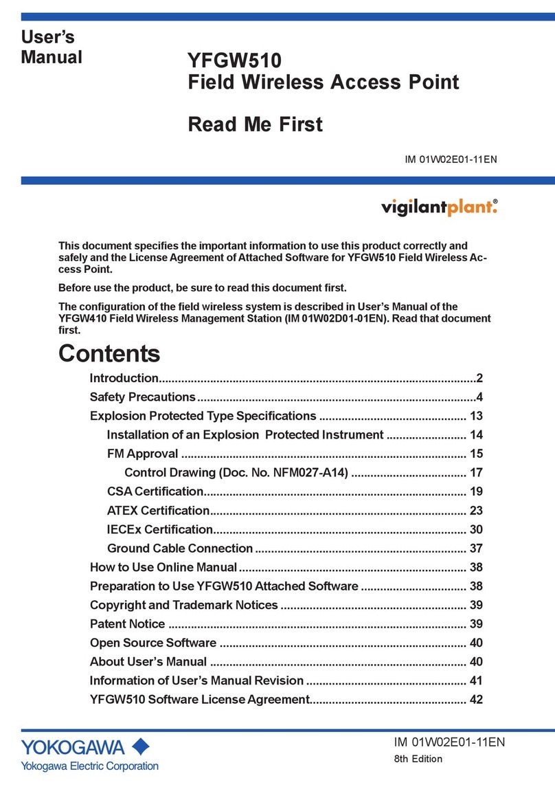
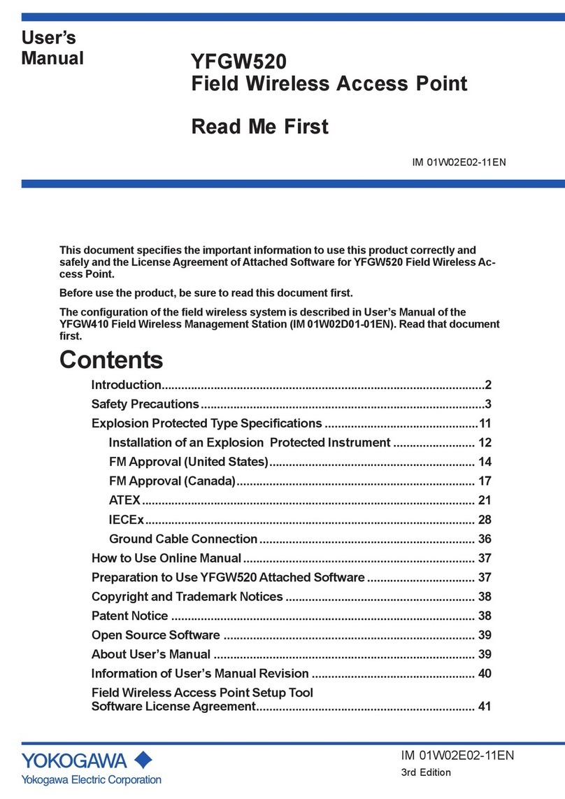
YOKOGAWA YFGW520 User manual

User’s
Manual YFGW520
Field Wireless Access Point
IM 01W02E02-01EN
IM 01W02E02-01EN
1st Edition

Toc-1
IM 01W02E02-01EN
YFGW520
Field Wireless Access Point
IM 01W02E02-01EN 1st Edition
CONTENTS
Introduction ..............................................................................................................i
Safety Precautions...................................................................................................i
About Radio Wave...................................................................................................ii
About Laser Safety .................................................................................................ii
Documentation Conventions................................................................................iii
Information of Revision.........................................................................................iv
PART-A. OVERVIEW OF FIELD WIRELESS SYSTEM
A1. Introduction.............................................................................................A1-1
A2. SystemConguration............................................................................A2-1
ThisdocumentcontainsimportantinformationaboutusingtheYFGW520FieldWirelessAccess
Pointproperlyandsafely.Pleasereadthisdocumentthoroughlybeforeusingthisproduct.
ThecongurationoftheeldwirelesssystemisdescribedintheUser’sManualoftheYFGW410
FieldWirelessManagementStation(IM01W02D01-01EN).Readthatdocumentrst.
1st Edition: Mar. 2018 (KP)
All Rights Reserved, Copyright © 2018, Yokogawa Electric Corporation

Toc-2
IM 01W02E02-01EN
PART-B. FUNCTIONSOFYFGW520
B1. Functions of YFGW520 ..........................................................................B1-1
B2. Structure and Parts of YFGW520..........................................................B2-1
B2.1 FrontView ....................................................................................................... B2-1
B2.2 RearView ........................................................................................................ B2-2
B2.3 SideView......................................................................................................... B2-4
B3. LED Display Function ............................................................................B3-1
B4. MechanicalOperatingParts..................................................................B4-1
B5. CheckingtheProduct ............................................................................B5-1

Toc-3
IM 01W02E02-01EN
PART-C. INSTALLATION
C1. Installation Environment .......................................................................C1-1
C2. PowerSupplyandGrounding ..............................................................C2-1
C2.1 PowerSupply ................................................................................................. C2-1
C2.2 Grounding....................................................................................................... C2-1
C3. Requirements for Installation ...............................................................C3-1
C3.1 Requirements for Installation Locations..................................................... C3-1
C3.2 Notes on Installation...................................................................................... C3-2
C4. Mounting .................................................................................................C4-1
C5. Wiring.......................................................................................................C5-1
C5.1 PowerSupplyCableConnection ................................................................. C5-1
C5.2 GroundingCableConnection....................................................................... C5-3
C5.3 NetworkCableConnection........................................................................... C5-5
C5.3.1 Metal Network Cable Connection................................................... C5-5
C5.3.2 Optical Network Cable Connection................................................. C5-6
C5.4 InstallationandWiringofAntenna............................................................... C5-8
C5.4.1 Mounting ISA100.11a Antenna to YFGW520................................. C5-8
C5.4.2 Remote Installation and Wiring of ISA100.11a Antenna ................ C5-9
C6. ExplosionProofWiring..........................................................................C6-1

Toc-4
IM 01W02E02-01EN
PART-D. SETUP
D1. InitialConguration ...............................................................................D1-1
D2. Setup Tool ...............................................................................................D2-1
D2.1 System Requirements................................................................................... D2-1
D2.1.1 Hardware ........................................................................................ D2-1
D2.1.2 Software.......................................................................................... D2-1
D2.1.3 Connection Example....................................................................... D2-2
D2.2 Installation Procedure ................................................................................... D2-3
D2.2.1 Driver for Infrared Adapter .............................................................. D2-3
D2.2.2 Field Wireless Access Point Setup Tool.......................................... D2-4
D3. CongurationMethod............................................................................D3-1
D3.1 WindowDesign .............................................................................................. D3-1
D3.2 Display/EditModeSwitching........................................................................ D3-2
D3.3 Backbone Interface........................................................................................ D3-4
D3.4 Maintenance ................................................................................................... D3-6
D3.5 Version Information ....................................................................................... D3-8

Toc-5
IM 01W02E02-01EN
PART-E. OPERATION AND MAINTENANCE
E1. Routine Maintenance .............................................................................E1-1
E2. Additions and Replacements................................................................E2-1
E3. Maintenance in Hazardous Areas.........................................................E3-1
E4. ComponentsHavingDenedLifeSpans ............................................E4-1

Toc-7
IM 01W02E02-01EN
PART-G. SPECIFICATIONS
G1. StandardSpecications ....................................................................... G1-1
G1.1 CommunicationInterfaceSpecications.................................................... G1-1
G1.2 GeneralSpecications .................................................................................. G1-2
G1.3 RegulatoryComplianceStatements............................................................ G1-3
G2. Model,SuxCodesandOptionCodes.............................................. G2-1
G3. External Dimensions............................................................................. G3-1
G3.1 100BASE-TX/100BASE-FX Model ................................................................ G3-1

i
<Read Me First>
IM 01W02E02-01EN
Introduction
This document describes the YFGW520 Field Wireless Access Point, which is a core compo-
nent of eld wireless networks. conforming to ISA100.11a, a wireless communication standard
for industrial automation that was drawn up by the International Society of Automation (ISA).
YFGW520 is a successor to YFGW510, enabling robust and longer distance backbone network
construction. YFGW520 supports two types of optical ber communication option, makes it pos-
sible to construct a noise resistant and long distance (max 5 km) backbone network by combining
with YFGW610. Outline, setup, settings, start-up, operation and maintenance of the entire eld
wireless system including the eld wireless network and eld wireless backbone are described in
the User’s Manual of the YFGW410 Field Wireless Management Station (IM 01W02D01-01EN).
Read that document rst.
NOTE
YFGW520 is displayed as YFGW510 on various setting screens in the Congurator included in
the Field Wireless Management Console of YFGW410.
Safety Precautions
NOTE
Read the safety precautions for this product that are described in YFGW520 Field Wireless
Access Point Read Me First (IM 01W02E02-11EN).

ii
<Read Me First>
IM 01W02E02-01EN
About Radio Wave
IMPORTANT
• This product is equipped with a wireless module which is designated as a certication of
construction type as a wireless facility for 2.4 GHz band low-power data communication
system of the Radio Act.
Refer to G1.3 Regulatory Compliance Statements for detail.
Due to the designated certication type, users may be subject to legal punishment in case
of:
- Disassembling or modifying the wireless module or antenna in this instrument
- Peeling o the certication label attached to the wireless module in this instrument
• RF Transmitter Power
The factory default settings of RF transmitter power is depends on the antenna type for
ISA100.11a.
ISA100.11a antenna code: 1
RF transmitter power is 7.9 dBm (9.9 dBm EIRP with +2 dBi antenna)
ISA100.11a antenna code: A
RF transmitter power is 0.9 dBm (9.9 dBm EIRP with +9 dBi antenna)
RF transmitter power depends on the region and the antenna type. In order for the wireless
output of an antenna to get the maximum which the area permits, adjustment by service of
Yokogawa is required.
• Microwave ovens and other industrial, scientic and medical equipment, as well as local
wireless stations (license required) and specic low-power wireless stations (license not
required) for identifying mobile objects used in the production line of a factory, use the same
frequency band as this product. Prevent interference with other wireless stations.
• Check that local wireless stations and specic low-power wireless stations are not being
used in the vicinity before using this product.
• If this product causes radio interference in a local wireless station used for identifying mobile
objects, change the working frequency or stop the emission of radio waves immediately. For
details on how to prevent radio interference, contact our service oce.
• Although this product has been designed to resist high frequency electrical noise, if a radio
transceiver is used near the transmitter or its external wiring, the transmitter may be aected
by high frequency noise pickup. To test this, start out from a distance of several meters and
slowly approach the transmitter with the transceiver while observing the measurement loop
for noise eects. Thereafter use the transceiver outside the range where the noise eects
were rst observed.
About Laser Safety
100BASE-FX(Single mode Fiber) model of YFGW520 is compliant with IEC 825-1 Class 1 and
CDRH 21-CFR 1040 Class 1 eye safety requirements.
CAUTION
• To avoid eye injury although, please do not see a light source.

iii
<Read Me First>
IM 01W02E02-01EN
Documentation Conventions
n TypographicalConvention
The following typographical conventions are used throughout this document:
l Conventionscommonlyusedthroughoutthisdocument
Characterstringtobeentered
The characters to be entered are shown in one-byte characters as follows:
Example:
FIC100.SV=50.0
“”Mark
Indicates a space between character strings to be entered.
Example:
.AL PIC010 -SC
Characterstringenclosedbybrackets({})
Indicates an option that can be omitted.
Example:
.PR TAG {. Sheet name}
l Conventionsusedtoshowkeyorbuttonoperations:
Charactersenclosedbybrackets([])
Characters enclosed by brackets within any description on a key or button operation, indicate
either a key on the HIS (Human Interface Station) keyboard, a key on the operation keyboard, a
button name on a window, or an item displayed on a window.
Example:
To perform the function, press the [OK] key.
Charactersenclosedbyangle-brackets(<>)
Characters eclosed by angle-brackets show the title of the screen during explanation of the soft-
ware operation.
nSymbols
The symbols used in this document are described in YFGW520 Field Wireless Access Point
Read Me First (IM 01W02E02-11EN).
n DrawingConventions
Some drawings may be partially emphasized, simplied or omitted for the convenience of de-
scription.
Some screen images depicted in the user’s manual may have dierent display positions or char-
acter types (e.g., upper/lower case). Also note that some of the images contained in this user’s
manual are display examples.

iv
<Read Me First>
IM 01W02E02-01EN
Information of Revision
DocumentName: YFGW520FieldWirelessAccessPoint
DocumentNumber: IM01W02E02-01EN
Edition Date Page Revised Item
1st March 2018 –New Issue

<A1. Introduction> A1-1
IM 01W02E02-01EN
PART-A. OVERVIEW OF FIELD
WIRELESS SYSTEM
A1. Introduction
Read the User’s Manual (IM 01W02D01-01EN) of the YFGW410 Field Wireless Management
Station (hereafter simply refered to as YFGW410) before reading this document.
The YFGW520 Field Wireless Access Point (hereafter simply refered to as YFGW520) is a core
component of eld wireless networks based on ISA100.11a, a wireless communication standard
for industrial automation. YFGW520 serves as an access point and forms the wireless backbone
network for the YFGW410 and the YFGW610 Field Wireless Media Converter (hereafter simply
refered to as YFGW610).

<A2.SystemConguration> A2-1
IM 01W02E02-01EN
A2. SystemConguration
This chapter describes the conguration for the eld wireless system including YFGW520.
Field Wireless
Management Console
Field Wireless
Access Point
(YFGW520)
Field wireless device
Field wireless
network
(ISA100.11a)
Field Wireless
Management Station
(YFGW410)
Host system
Field network
Field wireless
backbone network
Field wireless
network
FA0201.ai
Subnet A
Field Wireless
Management
Console
Field Wireless
Access Point
(YFGW520)
Field Wireless
Access Point
(YFGW520)
Field wireless device
Field wireless
network
(ISA100.11a)
Field Wireless
Management
Station
(YFGW410)
Subnet A
Host system
Field network
Field wireless
backbone network
Field wireless
network
FA0202.ai
FigureA2-1 Minimumconguration FigureA2-2 YFGW520-redundantconguration
Figure A2-1 shows the minimum conguration with a single YFGW520, and Figure A2-2 shows
the YFGW520-redundant conguration supported the Duocast technology (each eld wireless
device communicates with two YFGW520s).
The eld wireless backbone network consists of the YFGW410, the YFGW520 and the
YFGW610. Any of the following connection methods can be selected.
1. Metal network connection (100BASE-TX)
2. Optical ber network connection (100BASE-FX)
YFGW610 must be installed between YFGW520 and YFGW410 for optical ber network
connection to convert it to metal network connection.

<A2.SystemConguration> A2-2
IM 01W02E02-01EN
FA0203.ai
Field network
Information network (Ethernet)
NTP server
Field wireless management PC
Field Wireless Management Console
PRMHIS/ENGHIS
Field Wireless
Management
Station
(YFGW410)
Layer 2 switchLayer 2 switch
Control network (Ethernet)
Cable for redundancy
Layer 2 switch
(IEEE 1588)
Layer 2 switch
(IEEE 1588)
Layer 2 switch
(IEEE 1588)
Layer 2 switch
(IEEE 1588)
Layer 2 switch
(IEEE 1588)
Layer 2 switch
(IEEE 1588)
Field wireless
subnet B
Field wireless
subnet A
Field wireless
backbone network
Field wireless
network
Field Wireless
Access Point
(YFGW520)
Field wireless device
Field wireless
network
(ISA100.11a)
Field Wireless
Access Point
(YFGW520)
Field Wireless
Access Point
(YFGW520)
Field Wireless
Access Point
(YFGW520)
Field wireless
network
(ISA100.11a)
Field wireless device
Layer 3 switch
FCS
ALE111 x 2
FigureA2-3 YFGW410/YFGW520-redundantconguration
Figure A2-3 shows the YFGW410/YFGW520-redundant system conguration.
The Layer 2 switch between YFGW410 and YFGW520 must support the rapid spanning tree
protocol (RSTP) to prevent network loops, and the IEEE1588v2 (precision time protocol).
For recommended Layer 2 switches, see the User’s Manual of YFGW410 (IM 01W02D01-
01EN).
As shown above, eld wireless networks can be built with various system congurations.

<B1. Functions of YFGW520> B1-1
IM 01W02E02-01EN
PART-B. FUNCTIONSOFYFGW520
B1. Functions of YFGW520
The following block diagrams show communication functions of YFGW520 for each model.
FB0101.aiFB0101.ai
Communication function
Backbone communication
Internal clock
Initial communication
IPv4/ARP/ICMP/IGMP
ISA communication
Field wireless network
interface
Field wireless backbone
interface
ISA100.11a BBR 100BASE-TX
/100BASE-FX
FigureB1-1 100BASE-TX/100BASE-FXmodel
As shown above, the functions of the eld wireless backbone interface dier depending on
model.
YFGW520 with the 100BASE-FX model is equipped with a media converting board for metal
network/optical ber network. The metal network cable and optical ber network cable cannot be
used at the same time.
ISA100.11a BBR of the eld wireless network interface is for the eld wireless communication.
Initial communication shown in the block diagram is the function of setting parameters. It com-
municates to the Field Wireless Access Point Setup Tool via an infrared port through the glass
window on the front face of YFGW520.

<B2. Structure and Parts of YFGW520> B2-1
IM 01W02E02-01EN
B2. Structure and Parts of YFGW520
B2.1 FrontView
FB0201.ai
ISA100.11a antenna
Hazardous class name plate
Status indicator LED
(ACT, LAN, ISA)
unused
(C1, C2, AP)
Infrared port
FigureB2-1 FrontviewofYFGW520
The ISA100.11a antenna can be directly mounted on the connector, or remotely connected by
using an extension cable.
YFGW520 does not have any switches or buttons that can be mechanically operated from the
outside of the housing.

<B2. Structure and Parts of YFGW520> B2-2
IM 01W02E02-01EN
B2.2 RearView
FB0202-1.ai
ISA100.11a antenna
RJ-45 connector
Ground terminal
Power supply terminal
100BASE-TX model

<B2. Structure and Parts of YFGW520> B2-3
IM 01W02E02-01EN
FB0202-2.ai
ISA100.11a antenna
SC connector
Power supply terminal
Ground terminal
100BASE-FX model
FigureB2-2 RearviewofYFGW520
The power supply cable, grounding cable and communication cable are connected on the back
face of YFGW520. The electrical connection is provided on the bottom.
In the 100BASE-FX model, a media converter module is added to the 100BASE-TX model.

<B2. Structure and Parts of YFGW520> B2-4
IM 01W02E02-01EN
B2.3 SideView
FB0203.ai
ISA100.11a antenna
Tag plate
Electrical connection
Hazardous class name plate
FCC label
Main name plate
Ground terminal
right sideleft side
Electrical connection
FigureB2-3 SideviewofYFGW520
Other manuals for YFGW520
1
Table of contents
Other YOKOGAWA Wireless Access Point manuals
Popular Wireless Access Point manuals by other brands

Ruijie
Ruijie RG-AP730-L Series Hardware installation and reference guide

Quantum
Quantum QN-I-270 Quick setup guide

D-Link
D-Link DWL-1000AP Quick install guide

Edimax
Edimax EW-7428HCn user manual

SonicWALL
SonicWALL SonicWave 432i Safety and regulatory information

EnGenius
EnGenius EOC1650 quick start guide