York 6HK Series User manual

Johnson Controls Unitary Products 669997-UAI-H-0514
ACCESSORY KIT INSTALLATION MANUAL
ELECTRIC HEATER ACCESSORY (6HK SERIES)
FOR USE WITH MODELS: AHR / AHE / AHV / RFCX*E / RFCX*P
GENERAL INFORMATION
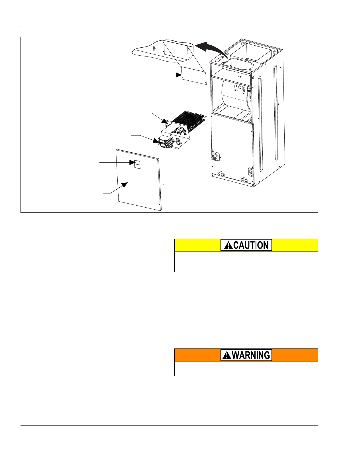
These instructions cover the installation of the following electric
heater models with AHR, AHE, and AHV single piece air han-
dlers. The 6HK series of electric heat kits use a single polarized
plug to easily connect the air handler power and controls.
These electric heat accessories are used for applications of
cooling with electric heat and heat pump with electric heat.
Each of the air handler unit models are approved for use with
specific electric heat accessories. The air handler unit installa-
tion instructions or name plate list the possible combinations
and other important electrical data and limitations. Refer to unit
instructions for further electrical specifications.
CLEARANCE
All installations of the 6HK electric heater kits are approved for
zero-clearance to combustibles when the minimum speed tap
on the blower motor is set per the air handler installation
instruction or nameplate. See air handler installation instruc-
tions for more information on changing motor speed taps.
MODELS
NOMENCLATURE - ELECTRICAL
ELECTRICAL SHOCK HAZARD
Installation or repairs made by unqualified persons can result
in hazards to you and others. Installation must conform with
local building codes or, in the absence of local codes, with
National Electrical Code ANSI/NFPA 70-1996 or current edi-
tion.
The information contained in this manual is intended for use
by a qualified service technician familiar with safety proce-
dures and equipped with the proper tools and test instru-
ments.
Shut OFF electric power at unit disconnect and/or service
panel before beginning the following procedures.
Failure to carefully read and follow all instructions in this man-
ual can result in malfunction, property damage, personal
injury, and/or death.
Verify edges of foil faced insulation are not in contact with any
exposed electrical connections.
TABLE 1: Models Covered
Heater kW
@ 240V 1 Phase
Heat Kit 1,2
1. (0,1) - 0 = no circuit breaker OR 1 = with circuit breaker.
2. (1,2) - 1 = with circuit breaker, no breaker jumper bar OR 2 = with circuit
breaker & breaker jumper bar.
3 Phase
Heat Kits
2.4 6HK(0,1)6500206 –
4.8 6HK(0,1)6500506 –
7.7 6HK(0,1)6500806 –
9.6 6HK(0,1)6501006 6HK06501025
12.5 6HK(1,2)6501306 –
14.4 6HK(1,2)6501506 6HK06501525
17.3 6HK(1,2)6501806 6HK06501825
19.2 6HK(1,2)6502006 6HK16502025
24.0 6HK(1,2)6502506 6HK16502525
6 Product Category 6 = Electric heat for AHR/AHE/AHV/RFCX*E/RFCX*P residential air handlers
HK Family Identifier HK = Electric Heater
1 Power Connection 0 = Terminal Block
1 = Circuit Breaker
2 = Circuit Breaker & Single Point wiring kit
65 Class Identifier 65 = Electric Heater
002 Electric Heat, Nom. kW 002=2.5kW; 005=5kW; 008=8kW; 010=10kW; 013=13kW;
013=13kW; 015=15kW; 018=18kW; 020=20kW; 025=25kW
25 Voltage Code 06 = 208/230-1-60
25 = 208/230-3-60
B Style Letter B = Indicates Sequential Change of Component Style

669997-UAI-H-0514
2Johnson Controls Unitary Products
INSTALLATION
Installation is the same for all Rev B model air handler operating
positions: upflow, downflow, and horizontal right or left. Only the
Rev B model air handler will work on the downflow position.
Installation of the Heater Kit should be done prior to unit instal-
lation in accordance with Table 2. Refer to figure 1 for depiction
of components.
1. Remove air handler blower access panel.
2. If Heat Kit has circuit breakers (if heat kit does not contain
circuit breakers, skip to step 3):
a. Examine the heat kit and take note of the number of
circuit breakers it has. Remove the appropriate num-
ber of circuit breaker knockouts from front of air han-
dler unit.
b. Cut blower access panel insulation behind the circuit
breaker plate and remove to open the area for the cir-
cuit breakers to protrude through the front access
panel and to provide clearance for circuit breakers and
single point wiring entry kit.
c. Replacement non-foil faced insulation for the exposed
front panel may then need to be added. Add rubber
gasket to inside of door for sealing.
3. Remove and recycle the duct cover from back panel of air
handler control and wiring compartment.
4. Install electric heat accessory.
a. Position and insert heat kit into opening in air handler.
b. Align mount holes and fasten the Heat Kit to the air
handler unit with 4 duct cover screws.
5. Remove and discard the air handler power connection wir-
ing that is for use without electric heat (the connector con-
taining only the red and black wires) from the 6 pin
connector.
6. Connect the heat kit's 6 pin socket connector to the control/
power 6 pin connector in the air handler. The end terminals
are “D” shaped to ensure polarization of the connector.
7. Mark an X in the appropriate box on the indoor unit rating
plate for the particular heater installed.
8. Refer to the unit rating plate for the minimum blower speed
required for the model heat kit installed.
FIGURE 1: Heater Installation
FIELD SUPPLY WIRING
LEFT SIDE
5.
SLIDE HEATER KIT INTO
AIR HANDLER AND ATTACH
WITH 4 DUCT COVER SCREWS
4.
BLOWER
ACCESS PANEL
1.
IF HEAT KIT TO BE INSTALLED
HAS FACTORY INSTALLED
CIRCUIT BREAKERS,
REMOVE CIRCUIT BREAKER
KNOCKOUTS.
2.
REMOVE
DUCT COVER
3.
A027-001
To prevent damage, carefully pass the accessory heating ele-
ment through the rectangular opening in the discharge duct.
Element mounting plate must be secured with 4 screws.
Verify edges of foil faced insulation are not in contact with any
exposed electrical connections.

669997-UAI-H-0514
Johnson Controls Unitary Products 3
TABLE 2: Heat Kit and Air Handler Compatibility
Heat Kit Model
and Revision Heat Kit
Description
Air Handler Compatibility
Rev A Air Handler
Upflow / Horizontal Rev B Air Handler
Downflow
1 PH
6HK06500206
Heat kits with terminal
blocks or 1 circuit breaker YES YES YES
6HK06500506
6HK06500806
6HK06501006
6HK16500206
6HK16500506
6HK16500806
6HK16501006
6HK16501306
Early version heat
kits with 2 or 3
circuit breakers YES YES NO
6HK16501506
6HK16501806
6HK16502006
6HK16502506
6HK26501306
6HK26501506
6HK26501806
6HK26502006
6HK26502506
6HK16501306B
Revision B heat kits with 2
or 3 circuit breakers YES YES YES
6HK16501506B
6HK16501806B
6HK16502006B
6HK16502506B
6HK26501306B
6HK26501506B
6HK26501806B
6HK26502006B
6HK26502506B
3 PH
6HK06501025 Heat kits with
terminal blocks YES YES YES6HK06501525
6HK06501825
6HK16502025 Early version heat
kits with 2 breakers YES YES NO
6HK16502525
6HK16502025B Revision B heat
kits with 2 breakers YES YES YES
6HK16502525B

669997-UAI-H-0514
4Johnson Controls Unitary Products
LINE POWER CONNECTIONS
Power may be brought into the unit through the outlet air end of
the unit (top left when unit is vertical) or the left side panel. To
minimize air leakage, seal the field wiring entry point.
Field wiring connects to heat kits with circuit breaker or terminal
block depending on the heat kit model. The multiple circuit, sin-
gle phase heater kits have options for a single power supply.
For the 3 phase 20kW and 25kW kits with multiple circuits, a
single point power accessory kit may be ordered separately. A
ground lug is also provided on the kits. Refer to unit instructions
for electrical specifications.
All wiring must comply with local and National Electrical Code
requirements. Read and heed all unit caution labels.
NOTICE
FIGURE 2: Heat Kit Connection
FACTORY WIRING ATTACHED
TO THIS SIDE
(Do not need to remove)
TERMINAL BLOCK OR
CIRCUIT BREAKERS
(May be 1, 2, or 3)
FIELD SUPPLY WIRING WILL
BE ATTACHED TO LEFT SIDE
FIGURE 3: Supply Power Connection
FIELD POWER WIRING
(208/230V)
COMPONENT CODES
GND - GROUND LUG
CB - CIRCUIT BREAKER
CKT - CIRCUIT
CN - WIRE CONNECTOR/NUT
GND
JUMPER BAR
SINGLE SOURCE POWER MULTI-SOURCE POWERMULTI-SOURCE POWER
WITH JUMPER BAR
TERMINAL BLOCK OR
CIRCUIT BREAKER
POWER
SUPPLY POWER
SUPPLY
SINGLE SOURCE POWER
TERMINAL BLOCK OR
CIRCUIT BREAKER
CKT 2
CKT 1
POWER
SUPPLY
CB
CB
CB
CB
CB
2 CIRCUITS ON 13KW-20KW
3 CIRCUITS ON 25KW
POWER
SUPPLY
GND
GND
GND
GND
POWER
SUPPLY
L1
L2
L1
L2
L1
L2
CKT 3
L1
L2
L1
L2 CB
CB
CB
L1
L2
L3
L1
L2
L3
L1
L2
L3
MULTI-SOURCE POWER
CKT 2
CKT 1
2 CIRCUITS ON 13KW-20KW
3 CIRCUITS ON 25KW
1 PHASE ELECTRIC HEAT OPTIONS:
3 PHASE ELECTRIC HEAT POWER OPTIONS:

669997-UAI-H-0514
Johnson Controls Unitary Products 5
ELECTRIC HEATERS & OPERATING
CONTROLS
LOW VOLTAGE CONTROL CONNECTIONS
The low voltage transformer and the fan control are standard on
all models.
The 24 volt power supply is provided by an internally wired low
voltage transformer which is standard on all air handler models.
Field supplied low voltage wiring can exit the unit on the top
right hand corner or the right hand side panel. Refer to Figure 1.
Remove desired knockout and pierce foil faced insulation to
allow wiring to pass through. Use as smallest hole possible to
minimize air leakage. Install a 7/8” plastic bushing in the
selected hole and keep low voltage wiring as short as possible
inside the control box. To further minimize air leakage, seal the
wiring entry point at the outside of the unit. The field wiring is to
be connected at the screw terminals of the control board.
For blower speed connections, electrical information and wir-
ing diagrams, see indoor unit installation instructions.
The electric heaters have both auto resettable and one shot
thermal limit controls.
If failure occurs, this one shot thermal limit control must be
replaced with a direct replacement.
NOTICE
NOTICE
All wiring must comply with local and national electrical code
requirements. Read and heed all unit caution labels.
NOTICE
FIGURE 4: Typical Installed Application
UPFLOW
HORIZONTAL RIGHT
HORIZONTAL LEFT
HEAT
HEAT
HEAT
DOWNFLOW
HEAT

Subject to change without notice. Published in U.S.A. 669997-UAI-H-0514
Copyright © 2014 by Johnson Controls, Inc. All rights reserved. Supersedes:669997-UAI-G-0413
York International Corp.
5005 York Drive
Norman, OK 73069
NOTES
This manual suits for next models
35
Table of contents
Other York Accessories manuals