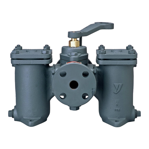
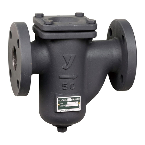
Yoshitake ST-10 User manual

■EPDT-263b■
MODEL ST-10
STRAINER
PRODUCT MANUAL
.
Thank you very much for choosing the Yoshitake’s product. To ensure the correct and safe use of the
product, please read this manual before use. This manual shall be kept with care for future references.
The symbols used in this manual have the following meanings.
Warning
This symbol indicates a potentially hazardous situation that, if not avoided,
could result in death or serious injury.
Caution
This symbol indicates a hazardous situation that, if not avoided, may result in
minor or moderate injury or may result in only property damage.
Table of Contents
1. Usage of the Product·················································· 1
2. Specifications···························································· 1
3. Dimensions and Weights············································· 2
4. Nominal Size Selection··············································· 4
5. Installation································································ 5
5.1 Piping Example ··················································· 5
5.2 Precaution for Installation ······································ 6
6. Operation································································· 7
6.1 Precaution for Operation········································ 7
7. Maintenance····························································· 7
7.1 Troubleshooting···················································· 7
7.2 Daily and Periodic Inspections ································· 8
7.3 How to Detach/Clean the Screen······························ 8
7.4 Reassembly························································10
7.5 Exploded view ·····················································12
Warranty Information

1
■EPDT-263b■
1. Usage of the Product
The ST-10 strainer is used for dust removal in piping.
2. Specifications
Model ST-10
Nominal size 125-250A *1
Application Cold and hot water, Oil (Kerosene, Heavy oils A and B),
Other non-dangerous fluids
Maximum working pressure 1.0 MPa
Maximum temperature 80°C
Connection JIS 10K FF flanged
Installation posture Horizontal or vertical installation *2
Material Body Ductile cast iron
Screen Stainless steel
Connection
Perforation φ8-10P
Mesh Standard 60 mesh *3
Rust proof Electrodeposition coating
*1 Available with davit for 250A.
*2 If fluid flows from bottom to top, it is necessary to install devices such as blow valve. See details in “5.1
Piping Example” on Page 4.
*3 Available with 20, 40, 80 and 100 mesh.
Caution
Please confirm that the indications on the product correspond with the specifications
of the ordered product model before use.
* If they are different, please contact us without using the product.

2
■EPDT-263b■
3. Dimensions and Weights
・125~200A
No.
Parts name No.
Parts name
1 Body 10
Bolt
2 Cover 11
Nut
3 Stopper ring 12
Spring washer
4 Cover plate 13
Plug
5 Screen 14
Bolt
6 Handle 15
Plug
7 O-ring 16
Eye bolt
8 O-ring 17
Name plate
9 Thumbscrew 18
Rivet
* Eye bolt [16] is available only for 150 to 250A.
Nominal
size L H
1
H
2
Screen Plug
[13] Plug
[15] Weight
(kg)
ds Ls
125A 335 132 179.5
133 154.5
R1/2 R3/8 42
150A 385 147 198 158 182 R1/2 R3/8 60
200A 470 175 233 208 228 R1/2 R3/8 100
(mm)
AOB Cross-sectional view

3
■EPDT-263b■
・250A
・250A with Davit
Nomin
al size
L H
1
H
2
Screen Plug
[13] Plug
[15] Weight
(kg)
ds ls
250A 550 215 285 258 278 R1/2 R3/8 156
No.
Parts name
㉑
Davit
㉒
Davit handle
㉓
Hanging bracket
㉔
bracket
Weight
(kg)
160
※Davit mounting position A or B is optional.
(mm)

4
■EPDT-263b■
4. Nominal Size Selection
Select a strainer of the same nominal size as that of the pipe (nominal size of piping = nominal size of
strainer). Note that using a strainer of a smaller nominal size increases the pressure loss of the strainer
and may result in the pressure fallen below the specified level at the inlet side of the equipment (see Fig. 1
“Pressure Loss Chart”).
Fig.1 Pressure Loss Chart (For Water)
As a reference, the standard flow velocity is specified in the Japanese Industrial Standards (JIS) as a
guide to select an appropriate nominal pipe size. See the following table.
Standard flow velocity
Fluid Standard Flow
Velocity
Water, Oil 2 m/s (2-4)
*
The above table is based on the requirements in JIS F 7101:2002 “Shipbuilding - Pipes of machinery -
standard velocity of flow”.
∆P: Pressure loss MPa
V: Flow rate L/min
Nominal
size
Screen: Perforation = φ8-10P, Mesh = 60 mesh

5
■EPDT-263b■
5. Installation
5.1 Piping Example
Table 1. Weight of Cover Set
1. Clogging condition inside the product can be known from the differential pressure measured when
pressure gauges are installed before and after the product (see Fig. 2).
2. If fluid flows from bottom to top, install a blow valve in order to remove scale accumulated at the bottom of
riser pipe (see Fig. 3).
Size Weight (kg)
125A 12
150A 17
200A 28
250A 41
Fig. 2
Fig. 3
Pressure
gauge Pressure
gauge
Blow
valve

6
■EPDT-263b■
5.2 Precaution for Installation
Warning
Since the product is heavy, securely support it with lifting devices or the like while
installing. See the product weight specified in “3. Dimensions and Weights” on Page 2.
* Failure to follow this notice may cause falling accident of the product, resulting in
bodily injury.
Caution
1. When installing, check the direction of the product so that the fluid flowing and the arrow marked on
the product are in the same direction.
* Setting the product in wrong directions keeps the product from functioning properly.
2. Make sure to support pipes and to secure the product firmly.
* If an excessive piping stress is applied, the product may be deformed.
3. When installing, secure the space required for maintenance or inspection (cleaning of the screen)
as shown in Fig. 4.
* Failure to follow this notice hampers maintenance and inspection (cleaning of the screen).
4. Do not apply excessive load, torque or vibration to the product.
* Failure to follow this notice may result in fluid leakage.
5. Connect the product to the pipes securely.
* Improper connecting may cause fluid leakage from the pipes when vibration is applied to them,
resulting in property damage.
Fig. 4 Space required for maintenance and inspection
Nominal size H
125A 330
150A 380
200A 470
250A 560
H mm or more

7
■EPDT-263b■
6. Operation
6.1 Precaution for Operation
Warning
Before letting the fluid into the product, make sure that there is no danger when the
fluid flows at the ends of piping.
* The hot fluid, if spouted out, may scald your skin.
Caution
Use the product under a maximum pressure loss of 0.1 MPa or less. Periodically
clean the screen.
* The screen may be broken.
7. Maintenance
7.1 Troubleshooting
Trouble Cause Remedy
Fluid does not flow.
1.
The screen [5] is clogged.
1.
Disassemble the product and clean the
screen [5].
2.
Stop valves before or after the
product are closed.
2.
Open the stop valves.
Excessive
pressure loss.
1.
The screen [5] is clogged.
1.
Disassemble the product and clean the
screen [5].
2.
Pressure gauge is out of order.
2.
Replace the pressure gauge with a new
one.
3.
Nominal size of the product is to
o
small for the flow rate.
3.
Replace the product with a new one
proper for the flow rate (see Fig. 1
“
Pressure Loss Chart
”
on Page 3).
Foreign substances
are not removed.
1.
The sc
reen
[5] is damaged.
1.
Disassemble the product and replace the
screen [5] with a new one.
2.
The O
-
ring [8] is damaged.
2.
Replace the O
-
ring [8] with a new one.
When replacing the
screen [5], the
stopper ring [3] is not
rotated.
1.
There is residual pressure in the
product.
1.
Completely remove the pressure in the
product.
2.
The body [1]
and the stopper ring
[3] stick to each other.
2.
Detach the stopper ring [3
]
with
reference to “7.3 How to Detach/Clean
the Screen” on Page 7.
When replacing the
screen [5],
the cover [2] does
not come off.
1.
There is negative pressure in the
product.
1.
Whe
n removing the plug
[
15
]
, b
reak
negative pressure in the piping and detach
the cover [2].
2.
The cover [2] and the body [1]
stick to each other.
2.
Detach the cover [2] with reference to
“
7.3
How to Detach/Clean the Screen” on
Page 7.
Outside leakage.
1.
The
O
-
ring [7] is damaged.
1.
Replace the O
-
ring [7] with a new one.
2.
The cover [2] is not installed
properly.
2.
Install the cover [2] with reference to
“
7.4
Reassembly” on Page 9.

8
■EPDT-263b■
7.2 Daily and Periodic Inspections
Conduct daily and periodic inspection in order to maintain optimum performance of the product.
Daily inspection (once a day)
Item How to inspect When abnormality is found
Clogging of the
screen [5]. Check that pressure loss is 1.0 MPa or
less by using a pressure gauge. Disassemble the product and clean or
replace the screen [5].
Outside
leakage. Check the product visually. See “7.1 Troubleshoothing”.
Periodic inspection (once a year: Add the following item to the above daily inspection items)
Item How to inspect When abnormality is found
Clogging of the
screen [5]. Disassemble the product and check the
screen [5] visually. Clean or replace the screen [5].
7.3 How to Detach/Clean the Screen
Warning
Completely discharge the pressure inside of the product, piping and equipment prior
to detaching the screen. When fluid is hot, cool down the product.
* Failure to follow this notice may result in scalds or injury due to the residual
pressure.
(1) Check that the internal pressure is completely discharged.
(2) Remove the thumbscrew. (3) Lift the handles.
Check the reading of the
pressure gauge.

9
■EPDT-263b■
(4) Grab the handles, rotate the stopper ring
by 45°. *1
(5) Detach the cover. *2
(6) Rotate the screen by 45°. (7) Pull out the screen.
*1 If the stopper ring is not turned smoothly,
lift the handle strongly.
The cover is pushed down and the
stopper ring can be turned smoothly.
*2 To remove the cover, do not lift the both
handles at the same time but lift them
one by one. This will reduce the
resistance of the O-ring and facilitate
removal of the cover.
Lift the handle strongly.

10
■EPDT-263b■
(8) Detach the screen.
Clean the screen using compressed air or a detergent.
7.4 Reassembly
Caution
1. Clean the O-ring and its contact surface to remove foreign substances.
* Residual foreign substances may cause outside leakage.
2. Apply grease to the O-ring or its contact surface after wiping the old grease (recommended grease:
G-501 by Shin-Etsu Chemical Co., Ltd.).
* Failure to follow this notice may cause the O-ring to be damaged.
3. If the screen is deformed or damaged, replace it with a new one.
* Failure to follow this notice may keep the product from functioning properly.
4. If the O-ring is damaged or deteriorated, replace it with a new one.
* Failure to follow this notice may cause outside leakage.
5. Watch your fingers not to be caught between the body and the cover when installing the cover.
(1) Put the screen into the body. (2) Insert the tabs of the screen between the grooves
on the body. At this time, wipe the old grease and
apply new grease to the O-ring or its contact
surface.
O-ring
O-ring
contact
surface

11
■EPDT-263b■
(3) Rotate the screen by 45°. *3
(6) Lower each of the handles between the
stopper and install the thumbscrew. *4
*3 Rotate the screen until the top (left) corner
of the triangle embossed on the body is
aligned with the top (right) corner of the
triangle printed on the screen handle.
If these triangles are not aligned with each
other, the screen may come off during use.
Caution
Align corners of
the triangles.
NGThe handle is not
engaged with the
stopper by the
thumbscrew.
The handle is not
between the
stopper.
(5) Rotate the stopper ring until each
handle reaches the stopper.
(4) Install the cover to the body.
Push in the cover strongly until the stopper ring
tab comes in contact with the body.
At this time, wipe the old grease and apply new
grease to the O-ring or its contact surface.
Stopper
Warning
*
4
Before using the product, make sure to
lower each of the handles between the
stopper and install the thumbscrew.
It is very dangerous to use the product in
the following conditions. Failure to follow
this notice may cause the cover to come off.
NG

12
■EPDT-263b■
7.5 Exploded View
•The parts shown in the rectangle boxes are available as consumable supply.
For service life of each product, see the following table. (Due to the differences on the using
environments, the service life listed on table below is only reference)
No. Parts name Service life
(reference)
7 O-ring 3 years
8 O-ring 3 years
5 Screen 5 years
Eye bolt [16]
* [16] is available only for 150 to 250A.
Bolt [10]
[14] Bolt
[15] Plug
[16] Eye bolt
[6] Handle
[12] Spring washer
[11] Nut
Cover [2]
O-ring [7]
Screen [5]
O-ring [8]
Handle [6]
Body [1]
Plug [13]
[9] Thumbscrew
[13] Plug
[9] Thumbscrew
Cross-sectional view of the Body
Stopper ring [3]
[4] Cover plate
Cover Set
Table of contents
Other Yoshitake Water Filtration System manuals
Popular Water Filtration System manuals by other brands

S.I.T.A.
S.I.T.A. MIOLED Installation, operation and maintenance manual

Waterway
Waterway Crystal Water owner's guide

Brita
Brita C150 FINEST installation instructions

SANUSLIFE
SANUSLIFE ECAIA user manual

KENT
KENT EXCELL Mineral RO 11003 Instruction handbook for installation, operation and maintenance

Aquasana
Aquasana EQ-300 installation guide