-6-
■
EPDT
-
183b
■
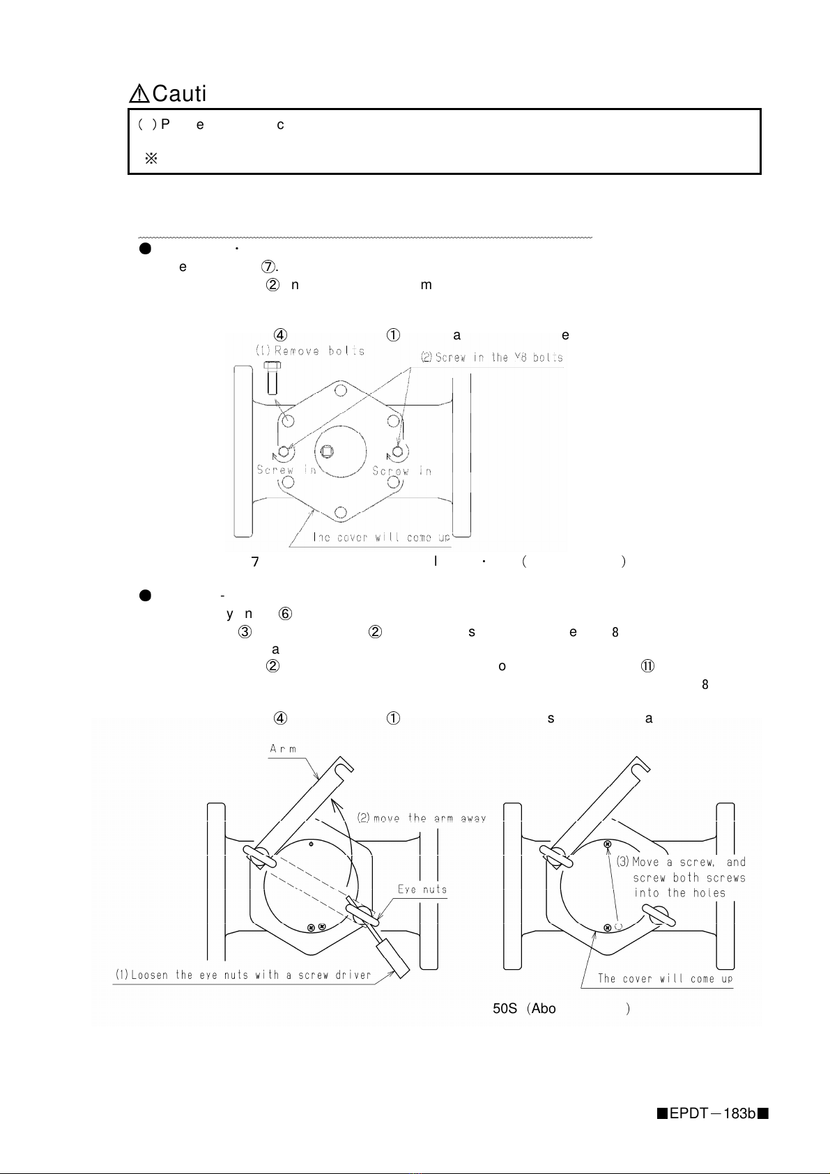
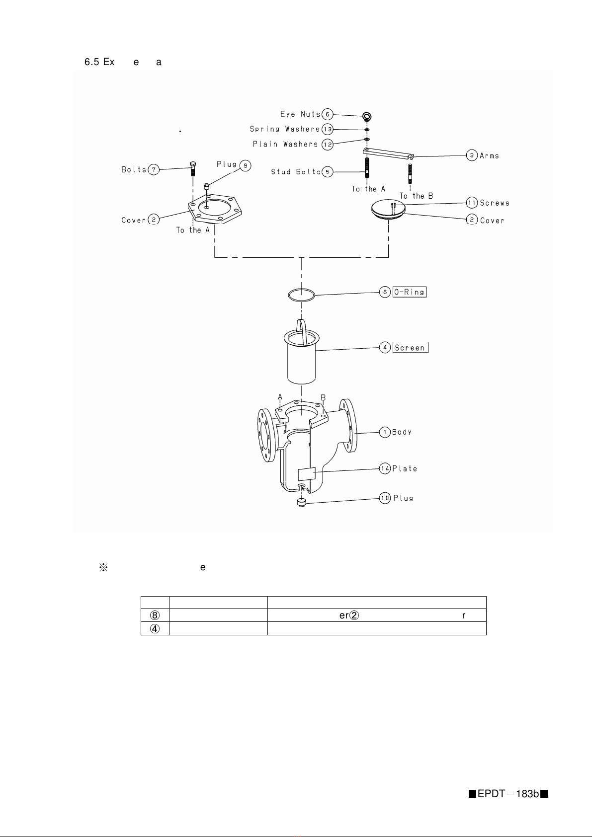
6.4 Assembly after disassembly
(1) Clean body
①
and the portions on cover
②
that come in contact with the O-ring.
(2) Assemble screen
④
onto the cleaned body.
(3) Apply silicone grease onto a new O-ring
⑧
and assemble it onto the slot on the cover
②
,
then assemble the cover onto the body.
(4-1) For Model SU-50
・
50H, tighten bolts
⑦
.
(4-2) For Models SU-50S, return arm
③
to the position of stud bolts
, then tighten the
eye nuts
⑥
.(Please confirm that the plain washers
⑫
and spring washers
⑬
have
been fit onto the arm before this.)
Cautions
(1) Clean body
①
and the portions on cover
②
that come in contact with the O-ring
⑧
.
※
Insufficient cleaning can result in outer leakages.
(2) Please take care not to damage the O-ring
⑧
upon assembly onto the cover
②
.
※
Damage can result in outer leakages.
(3) Use a new O-ring
⑧
, and apply silicone grease onto it.
※
A used O-ring may break and result in outer leakages. It may also become impossible to
remove the cover.
(4) In case screen
④
is deformed or damaged, exchange it to a new one.
※
The product will not function with a deformed or damaged screen.
(5) Securely assemble each part upon assembly.
※
Insecure assembly may result in deformation or damage to the parts.
(6) Upon assembly of Models SU-50S, confirm that the plain washers
⑫
and spring washers
⑬
have been fit onto the arm. (See Fig. 8.)
※
Neglect can cause deformation of the cover and arm resulting in outer leakages or other
damages.
(7) Upon assembly, make sure that bolts
⑦
and eye nuts
⑥
are tightened evenly on either side.
Please be careful not to tighten the eye nuts too tightly.
(
Refer to the torque values in Chart 3.
)
※
Neglect can cause deformation of the cover and arm resulting in outer leakages or other
damages.
Fig.9 Position for parts on Models SU-50S
※
Tighten the eye nuts till they come in close contact with the spring washers.
(Please be careful not to tighten the eye nuts too tightly.)
Chart 5 Tightening torque for the eye nuts (recommended values)
Nominal size Tightening torque
(
N
・
m
)
50, 65A 20
80
~
150A 30