www.youfibercable.com
6Fiber’s fusion flow
6.1 Start and stop
Fusion splicer can be supplied by outer battery, inner PS modules or AC adaptor.
Use AC adaptor or outer battery, please connect PS output with “DC 13.5V/5A”, turn switch to “DC”to start
machine.
1) Connect AC PS to power supply, insert DC PS to power supply modules where writes
POWER INPUT and switch to "ON " to start to work.
2) Use KL-01-26L7 , please turn switch to “ON”to start machine. Use KL-01-26L7,
Fusion Splicer can be supplied by inner battery or AC PS line connect to 220V PS; Use
KL-01-26AC PS modules, Fusion Splicer only can be supplied by AC PS line connect
to 220V power supply.
3) Turn switch to “OFF”to stop work.
●Notice:
Please charge the inner battery in time when use KL-01-26L7 PS modules. Power
specifications of the inner battery: DC 13.5V/5A. And please consult Addenda D Introduction
of power supply modules.
6.2 Preparation before fusion
6.2.1 Checking electrode
1> Make sure no fiber; electrodes are loaded well.
2> Connect with power then start machine, initialize the fusion splicer.
3> Observe arc electrodes; make sure that no obvious damage on electrode’s top.
4> Close wind shield
5> Arc to check state of electrode’s top, as following measures:
a> Press “MENU” to enter the first class menu.
b> Press “▲” or “▼” to make cursor “→” to point to “Maintenance”.
c> Press “ENT” to enter the menu of maintenance.
d> Press “▲” or “▼” to make cursor “→” to point to “clean electrode”, then
press “ENT” to make fusion splicer to arc.
e> Confirm normal; then press “MENU” to exit menu in turn.
5> Electrode aging: If you do not use the machine for long time, in order to assure splicing
quality, please operate “electrode aging”before the first splice, operate process is similar to process
“clean electrode”. “electrode aging”will arc electrode 20 times to clear the layer of oxide on electrode
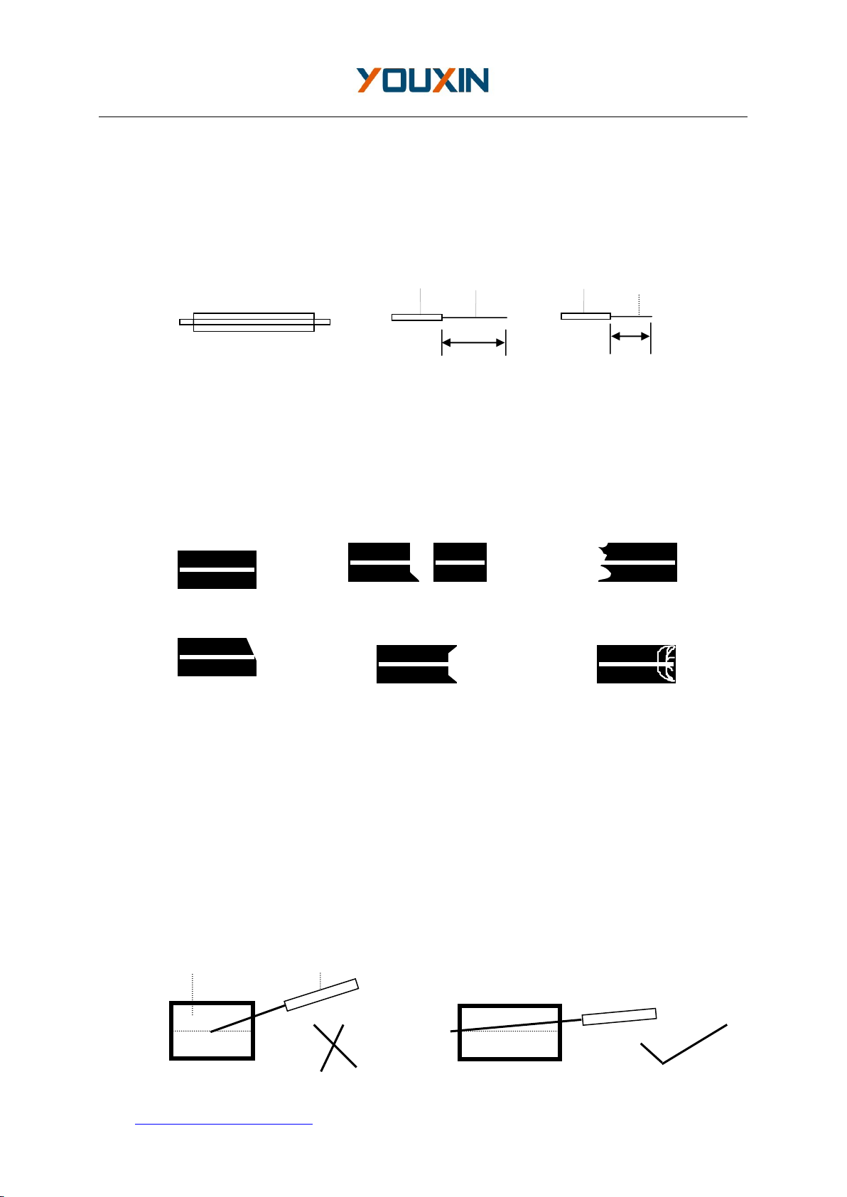
6.2.2 Fixing splice protection sleeve
To protect joint after fusion, you should enclose the fiber into the splice protection
sleeve. Please consult figures 4 (a).
Notice:
1> Make sure that there’s no dirt in the splice protection sleeve and surface of
fiber has been cleaned before fixing.
2> Make sure that fiber is in the splice protection sleeve.
3> To avoid influencing fusion’s target, please cut the otiose part if the inside core’s
length is longer than the sleeve’s coat.