Tappets Adjustment
1. Tappet clearance is pre-set at the factory.
2. Clearance adjustment may need after one hour of running time due
to initial wear. After adjustment, tappet clearance should be checked
during normal maintenance after every 10 hours of running to main
tain maximum performance.
3. Clearance adjustment should be done when the engine is cool.
4. The proper clearance setting is between 0mm (0.000”) and 0.1mm
(0.004”). The adjustment is achieved by loosening the locknut
(“Fig.2”) and turning the adjustment screw. The engine must be at
top dead center on the compression stroke before any adjustments
are made. This engine runs best with the valves set at a tight
setting. If the valves are set too loose, power will be affected.
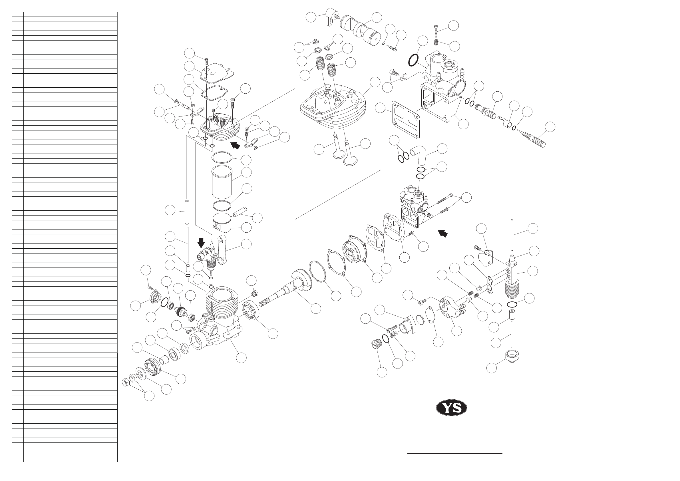
Cam Gear Timing
If for some reason you have to disassemble your engine, please follow
these important steps on reassembling the cam gear.
1. Remove the carburetor and back plate assembly. Notice the impres-
sion mark or dot opposite the rod journal on the crankshaft.
2. This mark is to point straight down or lined up with the outer case
seam line at the bottom and hold crankshaft securely.
3. Reinstall the cam with the dot facing you. After you fully installing
cam and then check dot should be pointing straight down will give
you right timing.
Operation of YS Super Mount (Option)
1. It is hold by 4 screws, 2 on the front ring and 2 on the rear soft
mount. There are two different height of spacer we provide.
A set spacer (MN110S) : 10mm thickness
B set spacer (MN111S) : 4mm thickness
2. Please be sure not to hit any part of the fuselage by the engine after
it is installed.
3. Ifdamperoilisleaked,rellTAMIYAdampersiliconoil#600.
Damperisaconsumptionparts,pleaseexchangeifyoundworn
or some defect.
Cleaning
This engine uses silicon rubber in many parts. Please use methanol or
model engine fuel for cleaning. Do not use Kerosene, Gasoline, Machine
oil, Automobile parts cleaner or house hold lubricants to clean. It will
harm silicon parts.
Engine Cooling
Be sure to secure cooling air for engine cooling. If it is not enough for the
engine, it causes the regulator and carburetor heat up and makes vapor-
ized or percolates the fuel. It gets deteriorations of engine performance
or stop the engine. Please read carefully below for provision.
1. Please open air intakes and outlets as wide as possible.
2. Take off cowling when you make engine adjustment for a long time.
When air temperature is high, it may heat up the regulator and car-
buretor to make vaporized or percolate the fuel even without cowl-
ing. If it happens, wait till engine well cooling down before you
restart and adjust.
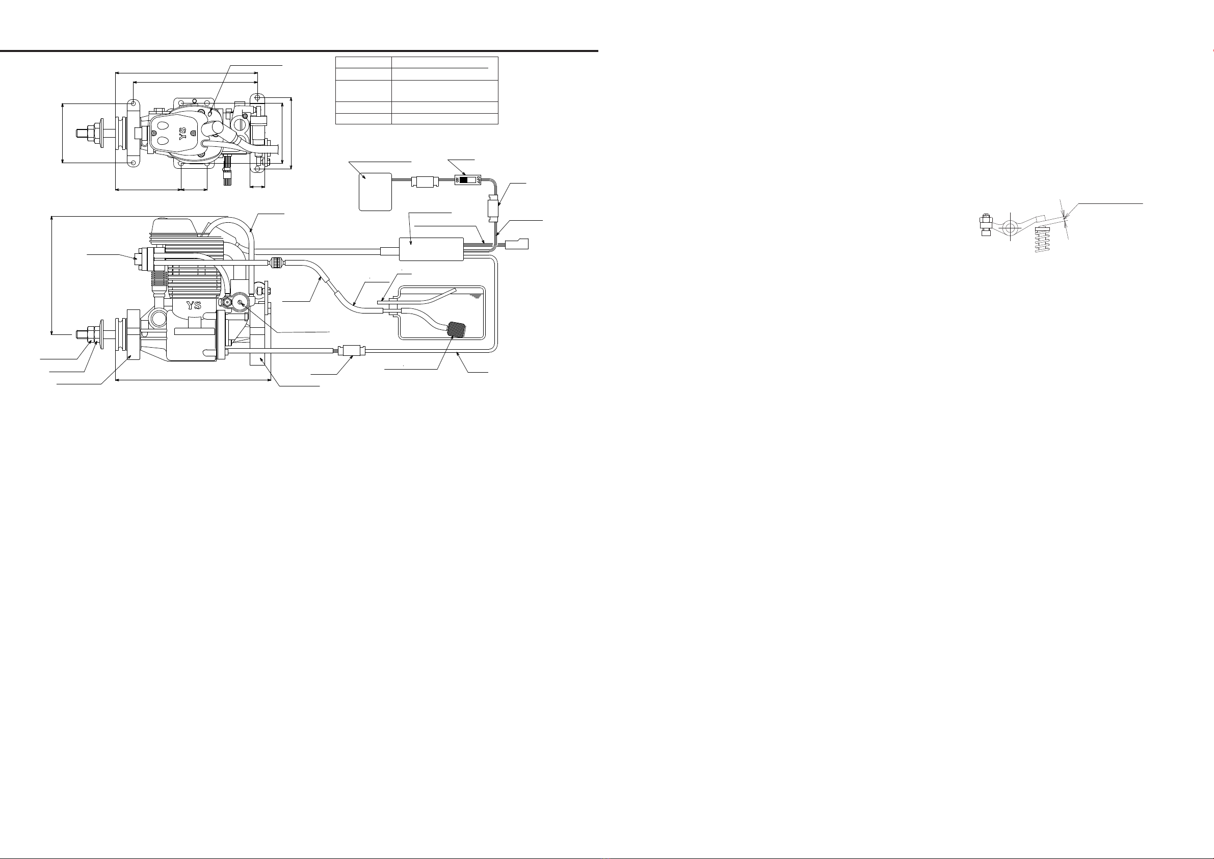
Tube C in FIG.1
Use the soft silicon tube ( inter 3mm, outer 5mm ).
57
136.5
14
119.4
68.6
149.5
63 25
58
114
Air
TubeB
FuelClunkTank
Regulator
FrontNut
RearNut
FrontMount RearMount
Battrery(4.8~8.4V) Switch
Red
Black
IgnitionBox
TubeA
BrownBlackYellow
Black
RedBlack
PlugCapScrew
Break-inNeedle
TubeC
*Pleasetaplightlywithasmallhammer,
asthesparkplugcapistightfittothe
sparkplug.
Safety Instructions
In order to use the engine, please read through this instruction manual
carefully. This is a complex,high-performance engine. If you have any
difcultiestounderstandanypartofthisinstructionmanual,pleasecon-
tact the hobby shop from whom you purchased the engine, or contact us
directly.
1. The propeller double locknut assembly supplied with the engine
must be used when mounting the propeller.
2. Alwaysuseagoodqualitypropellerandfollowthemanufacturer’s
instructions.
3. Choose a propeller size that will not allow the engine to exceed the
maximumpracticalRPMinight.
4. Always ensure that no people are in front of or beside the propeller
while the engine is running.
5. To start the engine, set the throttle to the idle position and use an
electric starter.
6. Afterstartingtheengine,alwaysmovebehindthepropellertoadjust
the needle settings.
7. The engine becomes extremely hot both during and after engine
runs.Donottouchtheengine,exhaustheader,mufer,oranyparts
attached to the engine while it runs or before it has cooled down.
8. Iftheenginerunsincorrectly,DON’TFLY.
9. Do not use this engine for anything other than radio controlled air
planes. Do not use it for radio controlled helicopters.
10.Youhavefullresponsibilitywhileyouoperatetheengine.Pleasebe
extra careful for your safety and the safety of others whenever you
operate the engine.
Installation
Connect the engine to the tank and CDI system as in “Fig.1”.
The battery and switch for the CDI unit is not supplied with the engine.
Thesoftmountandfuellterareoptional.
1. The recommended fuel tank size is 500cc to 700cc (18 to 24 oz).
A standard clunk type fuel tank may be used. If this type of tank is
used, you must use the special clunk supplied with the engine.
Please note that with this clunk, some fuel cannot be drained from
the tank. As soon as any part of the clunk becomes exposed, the
engine will stop due to air entering the fuel pump.
2. Alwaysuseafuelfilter.WerecommendYSfilter(6720).Withthisfiter,
youmustremovetheclothportionofthelterandleaveboththe
metallterscreensinplace.
3. Becauseoftheengine’spumpsystem,thetankmaybeplacednear
theaircraft’sC.Gpositrion.Thefuellevelinthetankwillnotinuence
the engine.
4. Pleasepayconsiderationtoavoidchangoftheignitionbox’swires
from vibration. Use the plastic “spiral wrap” supplied with the engine
to wrap the shielded plug wire.
5. Please place the ignition box about 15cm away from the receiver.
Some radio components may need to be over 30cm away from
ignition components to avoid interference. Wrap the ignition box in
foam rubber or other vibration absorbing material(in the same man-
ner as the receiver is mounted), and fasten (e.g. using Velcro straps).
Do not use the bracket holes to directly mount the ignition box to the
aircraft.
Fuel
1. Use a good quality alcohol based model engine fuel containing 5% to
25% nitro, and oil content 5% to 25%. Do not use gasoline fuel.
2. Whenllingthetank,disconnectFuelTube“A”orFuelTube“B”
(Fig.1)forlling,useastopperontheFuelTube“A”toavoidooding
the engine.
Propeller
1. Due to the high power ooutput of the DZ185CDI engine, it is supplied
with a double locknut system for added safety. Mount the propeler
and tighten the rear nut, followed by the front nut. The rear nut
has an offset shoulder that the recess of the front nut will secure itself
against.
2. Please check and retighten propeller locknut periodically.
3. Select a propeller that will allow the engine to run at a maximum of
between6,000to8,000RPM.
4. We recommend sizes 20x10.5, 20.5x10, 21X10. Other propeller
sizes may be used as long as the correct RPM range is maintained.
High Speed Needle Valve Adjustment
1. An electric starter is mandatory for this engine.
2. Turning the needle valve clockwise leans the mixture. Turning it
couner-clockwise richens the mixture. A good starting position for the
high speed needle valve is 1 and 1/2 turns open from the fully closed
postion.
3. To prime the engie, check that the ignition is switched OFF before
turning the engine over with an electric starter (throttle fully open)
4. Close the carburetor to the idle position, turn ignition ON and start
the engine with an electric starter. Run the engine at a high idle RPM
to warm it up.
5. Brake-in the engine with one or two tanks of fuel on the ground, with
good rich mixture setting adjusting for the best high speed needle
position.
6. Toachievebesthighspeedneedlevalveposition,runtheengine
with the throttle fully opened. Gradually turn the needle valve
clockwise untill the RPM beginns to drop. The position of the needle
valve corresponding to the maximum engine RPM is referred to as
the peak position. Turn the needle valve counter-clockwose
approximately 1/8 turns from the peak position.
Break in needle
Open break-in needle half turn in counter clockwise direction while
break-in. After break-in, close it to 1/6 turn or fully closed position. By
this procedure, fuel flows into crankcase through break-in needle. It
makes lubrication better and also prevents percolation (vapor rock) .
We recommend to open it a little under high tempreture in summer time.
NOTE: Engine power decrease as break-in needle open. When you
need maximum power, close the needle fully.
Breake-in
1. Start the engine with high speed needle valve open 1 and 1/2 turns
from the fully closed position and with the throttle at the idle position
2. After starting the engine, increases the RPM gradually by operating
the throttle. Do not suddenly apply full throttle.
3. Ifthemixtureistoorichandtheenginemisres,turntheneedle
valve clockwise to make the mixture leaner.
4. Breake-intheenginewithoneortwotanks(600ccor20oz.tank)of
fuel on the ground, running at the richest possible mixture setting.
Battery for CDI Unit
Use4.8~8.4VNi-Cd,Ni-MHorLi-Pobatterywithacapacityofaround
700mAh.Thiswillbesufcientfor5-10minutesights.
Idling adjustment
1. Ideal idling range is between 1,200 and 2,000RPM.
2. When the regulator is turned counter-clockwise, the idle mixture is
leaner. When the regulator is turned clockwise, the idle mixture is
richer. Adjust regulator in 45 degree increments.
3. Ifidlemixtureistoorich,theengine’sRPMwillgraduallydropand
the engine will eventually stop after continuous idling. Also if
the engine stops when you change the attitude of the airplane on
theground,theidlemixtureistoorich.Iftheengine’sidleRPMis
unstable during continuous idling, the idle mixture is too lean.
Spark Plug
Use spark plug supplied with the engine. The plug gap should be 0.30mm
(0.013”) and 0.45mm (0.018”). If plug gap become over 0.5mm (0.020”)
,theenginewillmisre.Ifthegapexceeds0.45mm,taptheelementwith
a hammer reduce to the gap.
FIG 1
Fig2
DZ185cdi RED
Bore 35mm
Stroke 31.8mm
Weight 965g ( Engine, Plug)
100g ( Ignition Box)
Displacement 30.6cc
Practical rpm 1,000~9,000rpm
OPERATOR'S MANUAL
Tappet Clearance